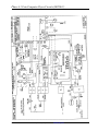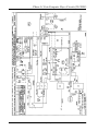
1
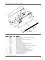
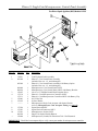
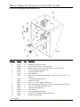
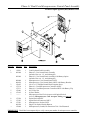
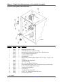
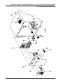
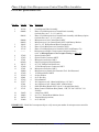
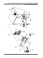
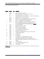
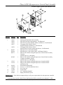
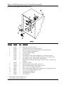
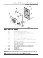
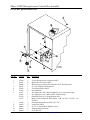
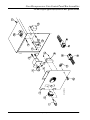
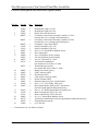
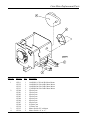
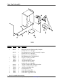
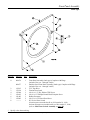
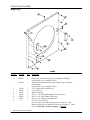
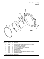
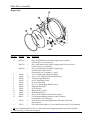
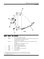
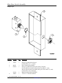
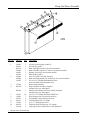
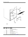
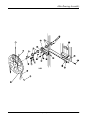
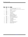
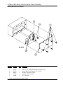
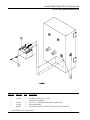
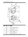
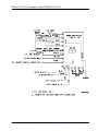
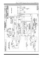
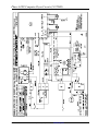
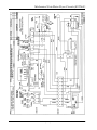
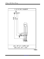
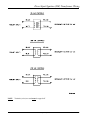
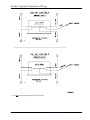
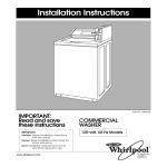
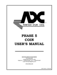
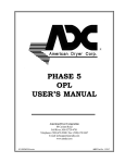
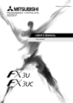
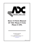
AD-285 Parts Manual
1987 thru 1991
American Dryer Corporation
88 Currant Road
Fall River, MA 02720-4781
Telephone: (508) 678-9000 / Fax: (508) 678-9447
e-mail: [email protected]
www.amdry.com
ADC Part No. 450085
Retain This Manual In A Safe Place For Future Reference
American Dryer Corporation products embody advanced concepts in engineering, design, and safety. If this product is
properly maintained, it will provide many years of safe, efficient, and trouble free operation.
ONLY qualified technicians should service this equipment.
OBSERVE ALL SAFETY PRECAUTIONS displayed on the equipment or specified in the installation manual included with
the dryer.
The following “FOR YOUR SAFETY” caution must be posted near the dryer in a prominent location.
FOR YOUR SAFETY
POUR VOTRE SÉCURITÉ
Do not store or use gasoline or
other flammable vapors and
liquids in the vicinity of this or
any other appliance.
Ne pas entreposer ni utiliser d’essence
ni d’autres vapeurs ou liquides
inflammables à proximité de cet
appareil ou de tout autre appareil.
We have tried to make this manual as complete as possible and hope you will find it useful. ADC reserves the right to make
changes from time to time, without notice or obligation, in prices, specifications, colors, and material, and to change or
discontinue models.
Important
For your convenience, log the following information:
DATE OF PURCHASE ____________________________
MODEL NO.
AD-285
__________________________________________
RESELLER’S NAME _______________________________________________________________________________________
Serial Number(s)
________________________________________________________________________________________
________________________________________________________________________________________
________________________________________________________________________________________
Replacement parts can be obtained from your reseller or the ADC factory. When ordering replacement parts from the factory,
you can FAX your order to ADC at (508) 678-9447 or telephone your order directly to the ADC Parts Department at (508)
678-9000. Please specify the dryer model number and serial number in addition to the description and part number, so that
your order is processed accurately and promptly.
The illustrations on the following pages may not depict your particular dryer exactly. The illustrations are a composite of the
various dryer models. Be sure to check the descriptions of the parts thoroughly before ordering.
“IMPORTANT NOTE TO PURCHASER”
Information must be obtained from your local gas supplier on the instructions
to be followed if the user smells gas. These instructions must be posted in a
prominent location near the dryer.
Table of Contents
High Security Control Door Assembly ..................................................................................................... 3
Phase 4.1 Single Coin Microprocessor Control Panel Assembly
For Direct Spark Ignition (DSI) Models Only ..................................................................................... 4
Phase 4.1 Single Coin Microprocessor Control Box Assembly
For Direct Spark Ignition (DSI) Models Only ...................................................................................... 5
Phase 4.1 Dual Coin Microprocessor Control Panel Assembly
For Direct Spark Ignition (DSI) Models Only ..................................................................................... 6
Phase 4.1 Dual Coin Microprocessor Control Box Assembly
For Direct Spark Ignition (DSI) Models Only ...................................................................................... 7
Phase 4 Single Coin Microprocessor Control Panel/Box Assemblies
For Glo-Bar® Ignition Models Only ................................................................................................. 8, 9
Phase 4 Dual Coin Microprocessor Control Panel/Box Assemblies
For Glo-Bar® Ignition Models Only ............................................................................................. 10, 11
Phase 4 OPL Microprocessor Control Panel Assembly
For Direct Spark Ignition (DSI) Models Only .................................................................................... 12
Phase 4 OPL Microprocessor Control Box Assembly
For Direct Spark Ignition (DSI) Models Only .................................................................................... 13
Phase 3 OPL Microprocessor Control Panel Assembly
For Glo-Bar® Ignition Models Only ................................................................................................... 14
Phase 3 OPL Microprocessor Control Box Assembly
For Glo-Bar® Ignition Models Only ................................................................................................... 15
Dual Timer Control Panel/Box Assemblies
For Direct Spark Ignition (DSI) Models Only .............................................................................. 16, 17
Dual Timer Control Panel/Box Assemblies
For Glo-Bar® Ignition Models Only ............................................................................................. 18, 19
Non-Microprocessor Coin Control Panel/Box Assemblies
For Direct Spark Ignition (DSI) and Glo-Bar® Ignition Models .................................................... 20, 21
Coin Meter Replacement Parts ............................................................................................................. 22
Coin Vault Assembly ............................................................................................................................. 23
Front Panel Assembly
Latch-Type ....................................................................................................................................... 24
Front Panel Assembly
Magnet-Type .................................................................................................................................... 25
Main Door Assembly
Latch-Type ....................................................................................................................................... 26
Main Door Assembly
Magnet-Type .................................................................................................................................... 27
Main Door Switch Assembly
N.S. Series ....................................................................................................................................... 28
Main Door Switch Assembly
Plunger-Type .................................................................................................................................. 29
Drop Lint Door Assembly ..................................................................................................................... 30
Lint Trap Assembly ............................................................................................................................... 31
Basket (Tumbler)/Support Assembly
Tapered Rib
For Models Mfd. as of April 18, 1991 ............................................................................................ 32
Basket (Tumbler)/Support Assembly
Standard Rib
For Models Mfd. prior to April 18, 1991 ........................................................................................ 33
Basket (Tumbler) Bearing Assembly ................................................................................................ 34, 35
Idler Bearing Assembly ................................................................................................................... 36, 37
Totally Enclosed, Fan-Cooled (T.E.F.C.) Motor Mount Assembly
For 60 Hz Models with Tapered Ribs Only ............................................................................... 38, 39
Totally Enclosed, Fan-Cooled (T.E.F.C.) Motor Mount Assembly
For 60 Hz Models with Standard Ribs Only .............................................................................. 40, 41
Totally Enclosed, Fan-Cooled (T.E.F.C.) Motor Mount Assembly
For 50 Hz Models with Tapered and Standard Ribs .................................................................. 42, 43
Sensor Bracket Assemblies ............................................................................................................. 44, 45
Direct Spark Ignition (DSI) Burner Assembly .................................................................................. 46, 47
Hi/Lo Microprocessor Burner Assembly
For Glo-Bar® Ignition Models Only ........................................................................................... 48, 49
Non-Microprocessor (Standard) Burner Assembly
For Glo-Bar® Ignition Models Only ........................................................................................... 50, 51
Sail Switch/Hi-Limit Assembly ........................................................................................................ 52, 53
Replacement Coil For 3/8” Hi/Lo Gas Valve
For Glo-Bar® Ignition Models Only ................................................................................................. 54
Replacement Coil For 3/8” Non-Hi/Lo Gas Valve
For Glo-Bar® Ignition Models Only ................................................................................................. 55
3-Phase (3Ø) Motor, Electric Relay Panel Assembly
Telemecanique (208/230 VAC Controls) ......................................................................................... 56
3-Phase (3Ø) Motor, Electric Relay Panel Assembly
Furnas (208/230 VAC Controls) ..................................................................................................... 57
Control/Heat Step Down Transformer
For Glo-Bar® Ignition Models Only ................................................................................................. 58
Outer Top/Back Guard Assembly ......................................................................................................... 59
Additional Parts Available ..................................................................................................................... 60
Microprocessor Coin Acceptor Listing .................................................................................................. 61
Wiring Diagrams .............................................................................................................................. 62-83
High Security Control Door Assembly
Illus. No.
Part No.
Qty.
1
160015
160104
160017
160016
112350
870011
800019*
1
1
1
1
1
1
1
800143
1
180203
102307
150201
150415
102600
102601
102503
1
3
4
4
1
1
1
2
3
4
5
6
7
8
9
10
11
*
Description
High Security MK-100 Lock Assembly ONLY with Key
MK-100 Key ONLY
Special Dummy Lock (noncoin models Only)
Lock Cam ONLY
ADC Logo ONLY
Logo Double Tape Kit
High Security Control Door Assembly Complete
(includes illus. nos. 4 through 7)
Stainless Steel High Security Control Door Assembly Complete
(includes illus. nos. 4 through 7)
Top Trim Strip with Lock Hole (28-3/8” length)
Trim Bumper Gasket (sold by the foot)
#10-32 x 1/4” Phillips Round Head Machine Screw
#10-16 x 1/2” Phillips Round Head Crimptite Screw
Control Door Support Rod Catch
Control Door Rod Retainer Clip
Control Door Support Rod
Specify color when ordering.
450085-8
Telephone: (508) 678-9000 / www.amdry.com
3
Phase 4.1 Single Coin Microprocessor Control Panel Assembly
For Direct Spark Ignition (DSI) Models ONLY
Illus. No.
1
2
3
4
5
6
7
8
9
10
---
Part No.
Qty.
112526
865098
1
1
865099
1
800040
800039
150415
137130
137131
152001
153012
--------
1
1
1
1
1
4
4
1
137056
137023
137021
865050
122800
1
1
3
1
1
Description
Coin Keyboard Label Assembly
Phase 4.1 Coin Control Panel Assembly
(includes illus. nos. 1, 2, and 4 through 6)
Phase 4.1 Coin Control Panel Assembly with Battery Option
(includes illus. nos. 1, 2, and 4 through 6)
Microprocessor Coin Control Panel ONLY
Microprocessor Coin Control Panel ONLY with Battery Bracket
#10-16 x 1/2” Phillips Round Head Crimptite Screw
Phase 4.1 Coin Microprocessor Controller ONLY
Phase 4.1 Coin Microprocessor Controller ONLY with Battery Clip
#8-32 Hex Nut
#8 Star Washer
Microprocessor Single Coin Acceptor with Optical Switch
(refer to Microprocessor Coin Acceptor Listing on page 61)
Optical Switch ONLY
Optical Switch Connector ONLY
Microprocessor Socket ONLY
Single Coin Optical Switch Harness
Microprocessor (female) Pin Extraction Tool...Not Illustrated
IMPORTANT: Check label on computer chip to verify correct part number for microprocessor controller.
4
American Dryer Corporation
450085-8
Phase 4.1 Single Coin Microprocessor Control Box Assembly
For Direct Spark Ignition (DSI) Models ONLY
Illus. No.
1
2
3
4
5
6
7
8
9
10
11
12
13
14
15
*
Part No.
Qty.
137021
137020
122800
150315
137022
137013
137151
12
1
1
1
1
4
1
136057
136052
150300
141403
150002
120715
151000
136057
150301
136008
*
*
2
1
2
1
2
*
*
1
Description
Microprocessor Socket ONLY
15-Pin Microprocessor Connector ONLY
Microprocessor (female) Pin Extraction Tool...Not Illustrated
#6 x 3/8” Phillips Pan Head Screw
15-Pin Strain Relief ONLY
Nylon Standoff
Motor Control Solid State Relay Board, 1 HP, 125 VAC - 250 VAC 1Ø
50/60 Hz
1/2-amp (Slo-Blo) Fuse ONLY
4-amp Fuse ONLY
#10-16 x 1/2” Hex Washer TEK Screw
Direct Spark Ignition (DSI) 24 VAC Transformer (for gas models Only)
#6-32 x 1” Round Head Machine Screw
30-Position Terminal Block
#6-32 Pal Nut
1/2-amp (Slo-Blo) Fuse ONLY
#8-18 x 7/16” Phillips Pan Head TEK Screw
Fuse Block/Strip ONLY
As required.
450085-8
Telephone: (508) 678-9000 / www.amdry.com
5
Phase 4.1 Dual Coin Microprocessor Control Panel Assembly
For Direct Spark Ignition (DSI) Models ONLY
Illus. No.
1
2
3
4
5
6
7
8
9
10
---
Part No.
Qty.
112526
865098
1
1
865099
1
800040
800039
150415
137130
137131
152001
153012
--------
1
1
1
1
1
4
4
1
137056
137023
137021
865050
122800
2
2
6
1
1
Description
Coin Keyboard Label Assembly
Phase 4.1 Coin Control Panel Assembly
(includes illus. nos. 1, 2, and 4 through 6)
Phase 4.1 Coin Control Panel Assembly with Battery Option
(includes illus. nos. 1, 2, and 4 through 6)
Microprocessor Coin Control Panel ONLY
Microprocessor Coin Control Panel ONLY with Battery Bracket
#10-16 x 1/2” Phillips Round Head Crimptite Screw
Phase 4.1 Coin Microprocessor Controller ONLY
Phase 4.1 Coin Microprocessor Controller ONLY with Battery Clip
#8-32 Hex Nut
#8 Star Washer
Microprocessor Dual Coin Acceptor with Optical Switch
(refer to Microprocessor Coin Acceptor Listing on page 61)
Optical Switch ONLY
Optical Switch Connector ONLY
Microprocessor Socket ONLY
Single Coin Optical Switch Harness
Microprocessor (female) Pin Extraction Tool...Not Illustrated
IMPORTANT: Check label on computer chip to verify correct part number for microprocessor controller.
6
American Dryer Corporation
450085-8
Phase 4.1 Dual Coin Microprocessor Control Box Assembly
For Direct Spark Ignition (DSI) Models ONLY
Illus. No.
1
2
3
4
5
6
7
8
9
10
11
12
13
14
15
*
Part No.
Qty.
137021
137020
122800
150315
137022
137013
137151
12
1
1
1
1
4
1
136057
136052
150300
141403
150002
120715
151000
136057
150301
136008
*
*
2
1
2
1
2
*
*
1
Description
Microprocessor Socket ONLY
15-Pin Microprocessor Connector ONLY
Microprocessor (female) Pin Extraction Tool...Not Illustrated
#6 x 3/8” Phillips Pan Head Screw
15-Pin Strain Relief ONLY
Nylon Standoff
Motor Control Solid State Relay Board, 1 HP, 125 VAC - 250 VAC 1Ø
50/60 Hz
1/2-amp (Slo-Blo) Fuse ONLY
4-amp Fuse ONLY
#10 x 1/2” Hex Washer TEK Screw
Direct Spark Ignition (DSI) 24VAC Transformer (for gas models Only)
#6-32 x 1” Round Head Machine Screw
30-Position Terminal Block
#6-32 Pal Nut
1/2-amp (Slo-Blo) Fuse ONLY
#8-18 x 7/16” Phillips Pan Head TEK Screw
Fuse Block/Strip ONLY
As required.
450085-8
Telephone: (508) 678-9000 / www.amdry.com
7
Phase 4 Single Coin Microprocessor Control Panel/Box Assemblies
For Glo-Bar® Ignition Models ONLY
8
American Dryer Corporation
450085-8
Phase 4 Single Coin Microprocessor Control Panel/Box Assemblies
For Glo-Bar® Ignition Models ONLY
Illus. No.
1
2
Part No.
Qty.
112526
800088
1
1
800168
1
800040
800039
150415
137110
137115
--------
1
1
1
1
1
1
17
137056
137023
137021
865050
150315
137020
137021
122800
137022
153012
152001
137013
137077
137061
137150
137151
1
1
3
1
1
1
14
1
1
4
4
4
1
1
1
2
18
19
20
21
136052
150002
120709
151000
2
2
1
2
3
4
5
6
7
8
9
10
11
12
13
14
15
16
Description
Coin Keyboard Label Assembly
Phase 4 Coin Microprocessor Control Panel Assembly
(includes illus. nos. 1, 2, 4, 13, and 14)
Phase 4 Coin Microprocessor Control Panel Assembly with Battery Option
(includes illus. nos. 1, 2, 4, 13, and 14)
Microprocessor Coin Control Panel ONLY
Microprocessor Coin Control Panel ONLY with Battery Bracket
#10-16 x 1/2” Phillips Round Head Crimptite Screw
Phase 4 Coin Microprocessor Controller ONLY
Phase 4 Coin Microprocessor Controller ONLY with Battery Clip
Microprocessor Single Coin Acceptor with Optical Switch
(refer to Microprocessor Coin Acceptor Listing on page 61)
Optical Switch ONLY
Optical Switch Connector ONLY
Microprocessor Socket ONLY
Single Coin Optical Switch Harness
#6 x 3/8” Phillips Pan Head Screw
15-Pin Microprocessor Connector ONLY
Microprocessor Socket ONLY
Microprocessor (female) Pin Extraction Tool...Not Illustrated
15-Pin Strain Relief ONLY
#8 Star Washer
#8-32 Hex Nut
Nylon Standoff
Arc Suppressor (A.S.) Board with Relays (115 VAC)
Arc Suppressor (A.S.) Board ONLY without Relays
Solid State Relay Board ONLY (for 115 volt application Only)
Motor Control Solid State Relay Board, 1 HP, 125 VAC-250 VAC 1Ø
50/60 Hz
4-amp Fuse ONLY
#6-32 x 1” Round Head Machine Screw
Terminal Strip (8-position)
#6-32 Pal Nut
IMPORTANT: Check label on computer chip to verify correct part number for microprocessor controller.
450085-8
Telephone: (508) 678-9000 / www.amdry.com
9
Phase 4 Dual Coin Microprocessor Control Panel/Box Assemblies
For Glo-Bar® Ignition Models ONLY
10
American Dryer Corporation
450085-8
Phase 4 Dual Coin Microprocessor Control Panel/Box Assemblies
For Glo-Bar® Ignition Models ONLY
Illus. No.
1
2
Part No.
Qty.
112526
800088
1
1
800168
1
800040
800039
150415
137110
137115
--------
1
1
1
1
1
1
17
137056
137023
137021
865051
150315
137020
137021
122800
137022
153012
152001
137013
137077
137061
137150
137151
1
1
3
1
1
1
14
1
1
4
4
4
1
1
1
2
18
19
20
21
136052
150002
120709
151000
2
2
1
2
3
4
5
6
7
8
9
10
11
12
13
14
15
16
Description
Coin Keyboard Label Assembly
Phase 4 Coin Microprocessor Control Panel Assembly
(includes illus. nos. 1, 2, 4, 13, and 14)
Phase 4 Coin Microprocessor Control Panel Assembly with Battery Option
(includes illus. nos. 1, 2, 4, 13, and 14)
Microprocessor Coin Control Panel ONLY
Microprocessor Coin Control Panel ONLY with Battery Bracket
#10-16 x 1/2” Phillips Round Head Crimptite Screw
Phase 4 Coin Microprocessor Controller ONLY
Phase 4 Coin Microprocessor Controller ONLY with Battery Clip
Microprocessor Single Coin Acceptor with Optical Switch
(refer to Microprocessor Coin Acceptor Listing on page 61)
Optical Switch ONLY
Optical Switch Connector ONLY
Microprocessor Socket ONLY
Dual Coin Optical Switch Harness
#6 x 3/8” Phillips Pan Head Screw
15-Pin Microprocessor Connector ONLY
Microprocessor Socket ONLY
Microprocessor (female) Pin Extraction Tool...Not Illustrated
15-Pin Strain Relief ONLY
#8 Star Washer
#8-32 Hex Nut
Nylon Standoff
Arc Suppressor (A.S.) Board with Relays (115 VAC)
Arc Suppressor (A.S.) Board ONLY without Relays
Solid State Relay Board ONLY (for 115 volt application Only)
Motor Control Solid State Relay Board, 1 HP, 125 VAC-250 VAC 1Ø
50/60 Hz
4-amp Fuse ONLY
#6-32 x 1” Round Head Machine Screw
Terminal Strip (8-position)
#6-32 Pal Nut
IMPORTANT: Check label on computer chip to verify correct part number for microprocessor controller.
450085-8
Telephone: (508) 678-9000 / www.amdry.com
11
Phase 4 OPL Microprocessor Control Panel Assembly
For Direct Spark Ignition (DSI) Models ONLY
Illus. No.
1
Part No.
Qty.
112535
112276
112275
112277
1
1
1
1
112278
1
800057
800164
800171
1
1
1
865095
1
3
137125
137126
1
1
4*
5
306052
150108*
152001
153000
137011
160005
1
4
4
4
4
1
2
6*
7*
8
Description
OPL English Keyboard Label Assembly
OPL Stick-On Labels (English Only)...Not Illustrated
OPL Stick-On Labels (Spanish, Italian, and Hebrew)...Not Illustrated
3-Language OPL Stick-On Labels
(English, Spanish, and Hebrew)...Not Illustrated
5-Language OPL Stick-On Labels
(Italian, Dutch, French, German, and Chinese)...Not Illustrated
Microprocessor Control Panel ONLY
Microprocessor Control Panel ONLY with Battery Bracket
Phase 4 OPL Non-Reversing Microprocessor Control Panel Assembly
Complete
(includes illus. nos. 1 through 8)
Phase 4 OPL Non-Reversing Microprocessor Control Panel Assembly
Complete with Battery Option
(includes illus. nos. 1 through 8)
Phase 4 OPL Non-Reversing Microprocessor Controller ONLY
Phase 4 OPL Non-Reversing Microprocessor Controller ONLY
with Battery Clip
Electrostatic Shield ONLY
#8-32 x 1/2” Pan Head Machine Screw
#8-32 Hex Nut
#8 Steel Burr
8-32” Aluminum Standoff
Spring Turn Latch (2-piece)
IMPORTANT: Check label on computer chip to verify correct part number for microprocessor controller.
*
12
Used on gas dryer models with the Direct Spark Ignition (DSI) system mfd. prior to March 13, 1989.
American Dryer Corporation
450085-8
Phase 4 OPL Microprocessor Control Box Assembly
For Direct Spark Ignition (DSI) Models ONLY
Illus. No.
1
2
3
4
5
6
7
8
9
10
11
12
13
Part No.
Qty.
137021
137020
122800
150315
137022
137013
137076
137078
137061
137151
12*
1
1
1
1
4
1
1
1
1
136052
131916
131930
150300
141403
150002
120715
120709
151000
1**
1
1
2
1
2
1
1
2
Description
Microprocessor Socket ONLY
15-Pin Microprocessor Connector ONLY
Microprocessor (female) Pin Extraction Tool...Not Illustrated
#6 x 3/8” Phillips Pan Head Screw
15-Pin Strain Relief ONLY
Nylon Standoff
Arc Suppressor (A.S.) Board with Relay (115 volt controls Only)
Arc Suppressor (A.S.) Board with Relay (208/230 volt controls Only)
Arc Suppressor (A.S.) Board ONLY without Relay
Motor Control Solid State Relay Board, 1 HP, 125 VAC - 250 VAC 1Ø
50/60 Hz
4-amp Fuse ONLY
Electromechanical Relay ONLY (115 VAC)
Electromechanical Relay ONLY (208/230 VAC)
#10-16 x 1/2” Hex Washer TEK Screw
Direct Spark Ignition (DSI) 24 VAC Transformer (for gas models Only)
#6-32 x 1” Round Head Machine Screw
30-Position Terminal Block
Terminal Strip (8-position)
#6-32 Pal Nut
* Some models require a quantity of 14.
** Some models require a quantity of 2.
450085-8
Telephone: (508) 678-9000 / www.amdry.com
13
Phase 3 OPL Microprocessor Control Panel Assembly
For Glo-Bar® Ignition Models ONLY
Illus. No.
1
Part No.
Qty.
112535
112276
112275
112277
1
1
1
1
112278
1
800057
800164
800161
1
1
1
800163
1
3
137092
137093
1
1
4
5
152001
160005
4
1
2
Description
OPL English Keyboard Label Assembly
OPL Stick-On Labels (English Only)...Not Illustrated
OPL Stick-On Labels (Spanish, Italian, and Hebrew)...Not Illustrated
3-Language OPL Stick-On Labels
(English, Spanish, and Hebrew)...Not Illustrated
5-Language OPL Stick-On Labels
(Italian, Dutch, French, German, and Chinese)...Not Illustrated
Microprocessor Control Panel ONLY
Microprocessor Control Panel ONLY with Battery Bracket
Phase 3 OPL Non-Reversing Microprocessor Control Panel Assembly
Complete
(includes illus. nos. 1 through 5)
Phase 3 OPL Non-Reversing Microprocessor Control Panel Assembly
Complete with Battery Option
(includes illus. nos. 1 through 5)
Phase 3 OPL Non-Reversing Microprocessor Controller ONLY
Phase 3 OPL Non-Reversing Microprocessor Controller ONLY
with Battery Clip
#8-32 Hex Nut
Spring Turn Latch (2-piece)
IMPORTANT: Check label on computer chip to verify correct part number for microprocessor controller.
NOTE: OPL microprocessor controllers listed are suitable for ALL voltage applications.
14
American Dryer Corporation
450085-8
Phase 3 OPL Microprocessor Control Box Assembly
For Glo-Bar® Ignition Models ONLY
Illus. No.
1
2
Part No.
Qty.
3
4
5
6
137020
137021
122800
150315
137022
137013
137077
137061
137150
137151
1
13
1
1
1
4
1
1
1
1
7
8
9
10
11
131916
136052
150002
120709
151000
2
2
2
1
2
450085-8
Description
15-Pin Microprocessor Connector ONLY
Microprocessor Socket ONLY
Microprocessor (female) Pin Extraction Tool...Not Illustrated
#6 x 3/8” Phillips Pan Head Screw
15-Pin Strain Relief ONLY
Nylon Standoff
Arc Suppressor (A.S.) Board with Relays (115 volt controls Only)
Arc Suppressor (A.S.) Board ONLY without Relays
Solid State Relay (115 volt application Only)
Motor Control Solid State Relay Board, 1 HP, 125 VAC - 250 VAC 1Ø
50/60 Hz
Electromechanical Relay ONLY (115 VAC)
4-amp Fuse ONLY
#6-32 x 1” Round Head Machine Screw
Terminal Strip (8-position)
#6-32 Pal Nut
Telephone: (508) 678-9000 / www.amdry.com
15
Dual Timer Control Panel/Box Assemblies
For Direct Spark Ignition (DSI) Models ONLY
Illus. No.
1
2
3
4
5
16
Part No.
Qty.
123000
123001
122400
865550
1
1
1
1
865551
1
800051
131812
131813
150207
1
1
1
2
Description
Red Indicator Light (115 volt)
Red Indicator Light (230 volt)
Rocker Heat Selector Switch
Dual Timer Control Panel Assembly Complete 115 VAC
(includes illus. nos. 1 through 21)
Dual Timer Control Panel Assembly Complete 230 VAC
(includes illus. nos. 1 through 21)
Dual Timer Control Panel ONLY
Push-To-Start Relay (115 volt)
Push-To-Start Relay (230 volt)
#10-24 x 1/2” Round Head Machine Screw
American Dryer Corporation
450085-8
Dual Timer Control Panel/Box Assemblies (continued)
For Direct Spark Ignition (DSI) Models ONLY
Illus. No.
Part No.
Qty.
6
7
8
9
154001
152013
153010
120708
120713
150002
150110
150001
131030
131031
151000
112050
160005
124103
124020
124021
124022
124023
122602
122700
122603
122701
122801
136002*
875250*
136052
136054
136056
141403
150300
150415
131814
131815
150002
120715
120709
151000
2
2
2
1
1
2
4
2
1
1
2
1
1
2
1
1
1
1
1
9
1
9
1
1
1
1
1
1
1
2
2
1
1
2
1
1
2
10
11
12
13
14
15
16
17
18
19
20
21
22
23
24
25**
26
27
28
29
30
31
32
Description
#10-24 Speed Nut
#6-32 Hex Nut
#6 Star Washer
3-Position Terminal Block
18-Position Terminal Block
#6-32 x 1” Round Head Machine Screw
#8-32 x 1/4” Phillips Head Machine Screw
#6-32 x 1/2” Round Head Machine Screw
Dual Timer Relay (115 volt)
Dual Timer Relay (230 volt)
#6-32 Pal Nut
Dual Timer Label ONLY
Spring Turn Latch (2-piece)
Arrow Timer Knob ONLY
60 Minute Timer (115 volt)
60 Minute Timer (230 volt)
15 Minute Timer (115 volt)
15 Minute Timer (230 volt)
9-Pin Connector ONLY
Pin Terminal ONLY
9-Pin Socket Connector ONLY
Socket Terminal ONLY
Pin/Socket Extraction Tool...Not Illustrated
Panel Mount Fuse Holder Assembly ONLY
In-Line Fuse Holder Assembly ONLY
4-amp Fuse ONLY
15-amp (Slo-Blo) Fuse ONLY
20-amp (Slo-Blo) Fuse ONLY
Direct Spark Ignition (DSI) 24 VAC Transformer
#10-16 x 1/2” Hex Washer TEK Screw
#10-16 x 1/2” Phillips Round Head Crimptite Screw
Motor Control Relay ONLY (115 volt)
Motor Control Relay ONLY (230 volt)
#6-32 x 1” Round Head Machine Screw
30-Position Terminal Block
Terminal Strip (8-position)
#6-32 Pal Nut
* Model application varies.
** Check fuse rating for verification.
450085-8
Telephone: (508) 678-9000 / www.amdry.com
17
Dual Timer Control Panel/Box Assemblies
For Glo-Bar® Ignition Models ONLY
18
American Dryer Corporation
450085-8
Dual Timer Control Panel/Box Assemblies
For Glo-Bar® Ignition Models ONLY
Illus. No.
1
2
3
4
5
6
7
8
9
10
11
12
13
14
15
16
17
18
19
20
21
22
23
24
25
26
27
28
450085-8
Part No.
Qty.
123000
123001
122400
865550
1
1
1
1
865551
1
800051
131812
131813
150207
154001
152013
153010
120708
120713
150002
150110
150001
131030
131031
151000
112050
160005
124103
124020
124021
124022
124023
122602
122700
122603
122701
122801
150415
131814
131815
150002
120709
151000
1
1
1
2
2
2
2
1
1
2
4
2
1
1
2
1
1
2
1
1
1
1
1
9
1
9
1
2
1
1
2
1
2
Description
Red Indicator Light (115 volt)
Red Indicator Light (230 volt)
Rocker Heat Selector Switch
Dual Timer Control Panel Assembly Complete 115 VAC
(includes illus. nos. 1 through 21)
Dual Timer Control Panel Assembly Complete 230 VAC
(includes illus. nos. 1 through 21)
Dual Timer Control Panel ONLY
Push-To-Start Relay (115 volt)
Push-To-Start Relay (230 volt)
#10-24 x 1/2” Round Head Machine Screw
#10-24 Speed Nut
#6-32 Hex Nut
#6 Star Washer
3-Position Terminal Block
18-Position Terminal Block
#6-32 x 1” Round Head Machine Screw
#8-32 x 1/4” Phillips Head Machine Screw
#6-32 x 1/2” Round Head Machine Screw
Dual Timer Relay (115 volt)
Dual Timer Relay (230 volt)
#6-32 Pal Nut
Dual Timer Label ONLY
Spring Turn Latch (2-piece)
Arrow Timer Knob ONLY
60 Minute Timer (115 volt)
60 Minute Timer (230 volt)
15 Minute Timer (115 volt)
15 Minute Timer (230 volt)
9-Pin Connector ONLY
Pin Terminal ONLY
9-Pin Socket Connector ONLY
Socket Terminal ONLY
Pin/Socket Extraction Tool...Not Illustrated
#10-16 x 1/2” Phillips Round Head Crimptite Screw
Motor Control Relay ONLY (115 volt)
Motor Control Relay ONLY (230 volt)
#6-32 x 1” Round Head Machine Screw
Terminal Strip (8-position)
#6-32 Pal Nut
Telephone: (508) 678-9000 / www.amdry.com
19
Non-Microprocessor Coin Control Panel/Box Assemblies
MAN0264
For Direct Spark Ignition (DSI) and Glo-Bar® Ignition Models
20
American Dryer Corporation
450085-8
Non-Microprocessor Coin Control Panel/Box Assemblies
For Direct Spark Ignition (DSI) and Glo-Bar® Ignition Models
Illus. No.
1
2
3
4
5
6
7*
8
9
10
11
12
13
14
15
16
17
18
19
20
21
*
Part No.
Qty.
123000
123001
122400
800070
1
1
1
1
800071
1
800052
131812
131813
150207
154001
125000
125003
150303
120713
1
1
1
2
2
1
1
2
1
120707
1
160005
122602
122700
122603
122701
122801
150300
141403
1
1
9
1
9
1
2
1
150415
131814
131815
150002
120715
120709
151000
2
1
1
2
1
1
2
Description
Red Indicator Light (115 volt)
Red Indicator Light (230 volt)
Rocker Heat Selector Switch
Coin Meter Control Panel Assembly Complete 115 VAC
(includes illus. nos. 1 through 6 and 8 through 12)
Coin Meter Control Panel Assembly Complete 230 VAC
(includes illus. nos. 1 through 6 and 8 through 12)
Coin Meter Control Panel ONLY
Push-To-Start Relay (115 volt)
Push-To-Start Relay (230 volt)
#10-24 x 1/2” Round Head Machine Screw
#10-24 Speed Nut
25¢ 115 Volt Meter (specify timing)
25¢ 230 Volt Meter (specify timing)
#4 x 3/4” Pan Head “A” Screw
18-Position Terminal Block
(for models mfd. as of May 15, 1989)
Terminal Strip (2-position)
(for models mfd. prior to May 15, 1989)
Spring Turn Latch (2-piece)
9-Pin Connector ONLY
Pin Terminal ONLY
9-Pin Socket Connector ONLY
Socket Terminal ONLY
Pin/Socket Extraction Tool...Not Illustrated
#10-16 x 1/2” Hex Washer TEK Screw
Direct Spark Ignition (DSI) 24 VAC Transformer
(for Direct Spark Ignition [DSI] models Only)
#10-16 x 1/2” Phillips Round Head Crimptite Screw
Motor Control Relay ONLY (115 volt)
Motor Control Relay ONLY (230 volt)
#6-32 x 1” Round Head Machine Screw
30-Position Terminal Block (for Direct Spark Ignition [DSI] models Only)
Terminal Strip (8-position)
#6-32 Pal Nut
Consult factory for coin meters not listed.
450085-8
Telephone: (508) 678-9000 / www.amdry.com
21
Coin Meter Replacement Parts
Illus. No.
1
2
3
4
22
Part No.
125511
125532
125512
125513
125500
125501
125502
125503
125504
125506
125507
125508
125510
125515
125516
Qty.
1
1
1
1
1
1
1
1
1
1
1
1
1
1
2
Description
1/60 RPM 115 Volt 60 Hz Meter Motor
1/60 RPM 230 Volt 60 Hz Meter Motor
1/60 RPM 240 Volt 50 Hz Meter Motor
1/30 RPM 240 Volt 50 Hz Meter Motor
2-Point Cam
3-Point Cam
4-Point Cam
5-Point Cam
6-Point Cam
8-Point Cam
9-Point Cam
10-Point Cam
12-Point Cam
Master Switch “B” with Arm
Master Switch “A” or “C”
American Dryer Corporation
450085-8
Coin Vault Assembly
Illus. No.
1
Qty.
802131
1
802130
1
4
802121
802120
160006
160007
160105*
802020
1
1
1
1
1
1
5
6
7
8
9
10
802019
802018
152014
309250
102503
102601
102600
1
1
4
1
1
1
1
2
3
*
Part No.
Description
Microprocessor Coin Vault Assembly Complete
(includes illus. nos. 1 through 6)
Non-Microprocessor Coin Vault Assembly Complete
(includes illus. nos. 1 through 6)
Microprocessor Coin Vault ONLY
Non-Microprocessor Coin Vault ONLY
Cam for 1/4 Turn Lock ONLY
1/4 Turn Lock with Key
1/4 Turn Mer-Pel Key ONLY
1/4 Turn Coin Box Assembly
(includes illus. nos. 2 through 5)
1/4 Turn Coin Box ONLY without Faceplate
1/4 Turn Coin Box Faceplate ONLY
1/4-20 Free Spin Wash Nut
Coin Vault Slot Cover
Control Door Support Rod
Control Door Rod Retainer Clip
Control Door Support Rod Catch
Specify key number when ordering.
450085-8
Telephone: (508) 678-9000 / www.amdry.com
23
Front Panel Assembly
Latch-Type
Illus. No.
1*
2
3
4
5
6
7
8
*
24
Part No.
Qty.
800676
1
800677
1
154215
170330
150300
150415
121405
150205
---------
2
1
1
8
1
2
1
Description
Front Panel Assembly (latch-type) Complete with Hinge
(includes illus. nos. 1 through 3 and 6)
Stainless Steel Front Panel Assembly (latch-type) Complete with Hinge
(includes illus. nos. 1 through 3 and 6)
5/32” Pop Rivet
Friction Door Latch
#10-16 x 1/2” Hex Washer TEK Screw
#10-16 x 1/2” Phillips Round Head Crimptite Screw
Rubber Grommet
#10-32 x 1/4” Fillister Head Screw
N.S. Series Door Switch
(for microprocessor models mfd. as of November 21, 1990
and non-microprocessor models mfd. as of November 15, 1990)
(refer to Main Door Switch Assembly on page 28)
Specify color when ordering.
American Dryer Corporation
450085-8
Front Panel Assembly
Magnet-Type
Illus. No.
1*
2
3
4
5
6
7
8
*
Part No.
Qty.
800389
1
800384
1
170340
154200
121405
150415
150300
150201
---------
2
1
1
8
1
2
1
Description
Front Panel Assembly (magnet-type) Complete with Hinge
(includes illus. nos. 1 through 3 and 6)
Stainless Steel Front Panel Assembly (magnet-type) Complete
without Hinge
(includes illus. nos. 1 through 3 and 6)
3-1/2” Stainless Steel Striker Pad
5/32” Pop Rivet
Rubber Grommet
#10-16 x 1/2” Phillips Round Head Crimptite Screw
#10-16 x 1/2” Hex Washer TEK Screw
#10-32 x 1/4” Phillips Pan Head Screw
N.S. Series Door Switch
(for microprocessor models mfd. prior to November 21, 1990
and non-microprocessor models mfd. prior to November 15, 1990)
(refer to Main Door Switch Assembly on page 29)
Specify color when ordering.
450085-8
Telephone: (508) 678-9000 / www.amdry.com
25
Main Door Assembly
Latch-Type
Illus. No.
26
Qty.
1*
800285
1
2
3
4
5
6
103050
150410
152014
102353
102210
170730
150431
1
4
4
1
1
1
1
7
*
Part No.
Description
Gray (lightweight) Main Door Assembly (latch-type) Complete
(includes illus. nos. 1 and 5 through 7)
12-1/2” Stainless Steel Main Door
#10-24 x 3/8” Phillips Pan Head Taptite Screw
1/4-20 Free Spin Wash Nut
Main Door Gasket
20-7/16” Door Glass
Glass Adhesive for Lightweight (plastic) Main Door Assembly
Main Door Latch Screw
Contact factory for colors other than gray.
American Dryer Corporation
450085-8
Main Door Assembly
Magnet-Type
Illus. No.
Part No.
Qty.
1*
800136**
1
800133**
1
800134**
1
2
3
4
5
6
7
8
9
10
11
12
13
103050
150410
152014
102350
102210
150002
102105
152013
306802
102102
150410
800131
1
4
4
1
1
2
2
2
6
4
4
2
---
170730
1
---
170725
1
Description
Gray (cast) Main Door Assembly (magnet-type) Complete
(includes illus. nos. 1 through 12)
Gray (cast) Main Door Assembly (magnet-type) Less Accessories
(includes illus. nos. 1 through 3)
Gray (cast) Main Door Assembly (magnet-type)
with Glass and Gasket ONLY
(includes illus. nos. 1 through 3, 5, and 6)
12-1/2” Stainless Steel Main Door Hinge
#10-24 x 3/8” Phillips Pan Head Taptite Screw
1/4-20 Free Spin Wash Nut
68-1/2” Main Door Gasket
20-7/16” Door Glass
#6-32 x 1” Round Head Machine Screw
Magnet Holder ONLY
#6-32 Hex Nut
Magnet Keeper ONLY
Door Magnet (0.215)
#10-24 x 3/8” Phillips Pan Head Taptite Screw
Cast Aluminum Magnet Holder Assembly Complete
(includes illus. nos. 7 through 11)
Glass Adhesive for Lightweight (plastic) Main Door Assembly...
Not Illustrated
Glass and Gasket Adhesive for Cast Main Door Assembly...Not Illustrated
* All dryers manufactured as of June 1, 1989 are built with a lightweight (plastic) main door assembly.
** Contact factory for colors other than gray.
450085-8
Telephone: (508) 678-9000 / www.amdry.com
27
Main Door Switch Assembly
N.S. Series
Illus. No.
Part No.
Qty.
1
2
313215
800445*
1
1
800446**
1
3
4
5
6
7
313217
150025
153045
137004
153045
152016
1
2
2
***
2
2
Description
Door Switch Actuator Arm ONLY
N.S. Series Microprocessor Main Door Switch Housing Assembly Complete
(for models mfd. as of November 21, 1990)
(includes illus. nos. 1 through 7)
N.S. Series Non-Microprocessor Main Door Switch Housing Assembly
Complete
(for models mfd. as of November 15, 1990)
(includes illus. nos. 1 through 7)
Main Door Switch Housing ONLY
#4-40 x 1” Pan Head Machine Screw
#4 Lock Washer
N.S. Series Main Door Switch ONLY
#4 Lock Washer
#4-40 Hex Nut
* Microprocessor model dryers require two (2) N.S. Series main door switches.
** Non-Microprocessor model dryers require one (1) N.S. Series main door switch.
***As required (either 1 or 2).
28
American Dryer Corporation
450085-8
Main Door Switch Assembly
Plunger-Type
Illus. No.
*
Part No.
Qty.
1
137003
1
2
3
401551
870010
*
1
4
313209
152003
1
1
Description
Plunger-Type Main Door Switch
(includes illus. nos. 1, 2, and 4)
Door Switch Spacer/Washer
Plunger-Type Main Door Switch Assembly Complete
(for microprocessor models mfd. prior to November 21, 1990
and for non-microprocessor models mfd. prior to November 15, 1990)
(includes illus. nos. 1 through 4)
Main Door Switch Housing ONLY
3/8-32 x 1/2” Door Switch Nut
As required (either 1 or 2).
450085-8
Telephone: (508) 678-9000 / www.amdry.com
29
Drop Lint Door Assembly
Illus. No.
1
2
3
4
5
6
7
8
9
10
--*
30
Part No.
Qty.
160001
160103
800150
160200
160003
160104
160008
160009
150425
1
1
1
1
1
1
1
1
1
157000
800234*
1
1
800244
1
150201
117600
102307
180213
150419
108120
150418
10
7
3
2
2
1
1
Description
AD-100 Lock Assembly with Key
AD-100 Key ONLY
Knob Latch Kit Assembly (for noncoin models)
Knob Latch Kit with two (2) Screws (for noncoin models)
Dummy Lock ONLY (for noncoin models)
MK-100 Key ONLY
Lock Cam ONLY (for AD-100 lock)
Knob Latch Adjustable Cam with Screw (for noncoin models)
#12-24 x 3/8” Round Head Machine Screw
(screw for knob latch adjustable cam)
Drop Lint Door Spring
Drop Lint Door Assembly Complete
(includes illus. nos. 4 through 8)
Stainless Steel Drop Lint Door Assembly Complete
(includes illus. nos. 4 through 8)
#10-32 x 1/4” Phillips Pan Head TEK Screw
Noise Suppression Tape (sold by the foot)
Trim Bumper Gasket (sold by the foot)
Trim/Kick Plate (28-3/8” length)
#6 x 1/2” Tamperproof Screw
Chain for Drop Lint Door (10-1/2” length)
Tamperproof Screw Hand Driver...Not Illustrated
Specify color when ordering.
American Dryer Corporation
450085-8
Lint Trap Assembly
Illus. No.
Part No.
Qty.
1
800410
1
2
3
4
5
6
7
800411
154200
304102
150300
800503
150419
108120
1
7
1
2
1
2
1
450085-8
Description
Lint Trap Assembly Complete
(includes illus. nos. 1 and 3 through 5)
Lint Trap ONLY
5/32” Pop Rivet
Lint Screen Holder ONLY
#10-16 x 1/2” Hex Washer TEK Screw
Lint Screen ONLY
#6 x 1/2” Tamperproof Screw
Chain for Drop Lint Door (10-1/2” length)
Telephone: (508) 678-9000 / www.amdry.com
31
Basket (Tumbler)/Support Assembly
Tapered Rib
For Models Mfd. as of April 18, 1991
Illus. No.
1
2
3
4
5
6
7
8
9
10
11
--32
Part No.
Qty.
800830
1
800890
1
800720
1
800844
1
301315
301316
301414
301415
150518
100902
153003
150415
800612
152004
153002
153001
116003
401010
2
1
2
1
1
3
3
30
1
3
3
3
1
1
Description
Tapered Rib Basket (tumbler) and Support Assembly Complete
with Felt Collar
(includes illus. nos. 1 through 11)
Stainless Steel (tapered rib) Basket (tumbler) and Support Assembly
Complete with Felt Collar
(includes illus. nos. 1 through 11)
Tapered Rib Basket (tumbler) ONLY without Felt Collar
(includes illus. nos. 1 through 3)
Stainless Steel (tapered rib) Basket (tumbler) ONLY without Felt Collar
(includes illus. nos. 1 through 3)
Short - Tapered Basket (tumbler) Rib ONLY
Tall - Tapered Basket (tumbler) Rib ONLY
Stainless Steel (short - tapered) Basket (tumbler) Rib ONLY
Stainless Steel (tall - tapered) Basket (tumbler) Rib ONLY
5/16-18 x 3/8” Socket Button Head Screw
5/16-18 x 31” Tie Rod
3/8” x 1-1/2” Fender Washer
#10-16 x 1/2” Phillips Round Head Crimptite Screw
Basket (tumbler) Support ONLY
5/16-18 Hex Nut
5/16” Lock Washer
5/16” Flat Washer
Felt Collar ONLY
#847 Adhesive for Felt Collar...Not Illustrated
American Dryer Corporation
450085-8
Basket (Tumbler)/Support Assembly
Standard Rib
For Models Mfd. prior to April 18, 1991
Illus. No.
1
2
3
4
5
6
7
8
9
10
11
--450085-8
Part No.
Qty.
800815
1
800863
1
800709
1
800853
1
301309
301409
150518
100902
153003
150415
800612
152004
153002
153001
116003
401010
2
1
1
3
3
30
1
3
3
3
1
1
Description
Standard Rib Basket (tumbler) and Support Assembly Complete
with Felt Collar
(includes illus. nos. 1 through 11)
Stainless Steel (standard rib) Basket (tumbler) and Support Assembly
Complete with Felt Collar
(includes illus. nos. 1 through 11)
Standard Rib Basket (tumbler) ONLY without Felt Collar
(includes illus. nos. 1 through 3)
Stainless Steel (standard rib) Basket (tumbler) ONLY without Felt Collar
(includes illus. nos. 1 through 3)
Standard Basket (tumbler) Rib ONLY
Stainless Steel (standard) Basket (tumbler) Rib ONLY
5/16-18 x 3/8” Socket Button Head Screw
5/16-18 x 31” Tie Rod
3/8” x 1-1/2” Fender Washer
#10-16 x 1/2” Phillips Round Head Crimptite Screw
Basket (tumbler) Support ONLY
5/16-18 Hex Nut
5/16” Lock Washer
5/16” Flat Washer
Felt Collar ONLY
#847 Adhesive for Felt Collar...Not Illustrated
Telephone: (508) 678-9000 / www.amdry.com
33
Basket (Tumbler) Bearing Assembly
34
American Dryer Corporation
450085-8
Basket (Tumbler) Bearing Assembly
Illus. No.
1
2
3
4
5
6
7
8
9
10
11
12
13
14
15
16
17
18
19
20
21
22
23
24
*
Part No.
Qty.
100203
153005
152005
150508
153005
152005
150600
153004
153005
152005
150501
153002
153001
150621
152004
801101
1
4
4
2
2
2
2
2*
2
2
4
4
4
2
2
1
801103
1
801105
801104
100202
152005
154303
101100
154301
100713
100111
1
1
1
2
2
1
2
1
1
Description
1-3/8” Flange Bearing ONLY
3/8” Lock Washer
3/8-16 Hex Nut
3/8-16 x 3/4” Hex Head Machine Bolt
3/8” Lock Washer
3/8-16 Hex Nut
3/8-16 x 1-1/2” Hex Head Machine Bolt
3/8” Flat Washer
3/8” Lock Washer
3/8-16 Hex Nut
5/16-18 x 3/4” Hex Head Machine Bolt
5/16” Lock Washer
5/16” Flat Washer
5/16-18 x 1-1/2” Hex Head Machine Bolt
5/16-18 Hex Nut
1-3/8” Bearing Box Assembly Complete
(includes illus. nos. 4 through 20)
1-3/8” Bearing Box and Support ONLY
(includes illus. nos. 4 ,5, 6, 16, and 17)
1-3/8” Bearing Box ONLY
Pillow Block Bearing Support ONLY
1-3/8” Pillow Block Bearing ONLY
3/8-16 Hex Nut
3/8-16 x 1-1/4” Allen Setscrew
18” Cast Pulley
5/16-18 x 5/16” Allen Setscrew
1/4” x 1/4” x 7/8” Key
5L-650 V-Belt (to idler assembly)
Some models require a quantity of 4.
450085-8
Telephone: (508) 678-9000 / www.amdry.com
35
Idler Bearing Assembly
36
American Dryer Corporation
450085-8
Idler Bearing Assembly
Illus. No.
Part No.
Qty.
1
2
3
100111
101129
100105
1
1
1
4
5
6
7
8
9
10
11
154301
100705
301850
152002
153007
100214
150521
801008
2
1
1
3
3
2
3
1
12
13
14
15
16
17
18
19
20
21
22
100406
150509
150617
153005
153004
152020
152004
152005
153005
150617
301851
801009
1
1
2
2
2
1
1
1
1
1
1
1
450085-8
Description
5L-650 V-Belt (to basket [tumbler]/support assembly)
9” x 2-1/2” x 3/16” Key, Pulley
4L-520 V-Belt (to Totally Enclosed, Fan-Cooled [T.E.F.C.] motor mount
assembly)
5/16-18 x 5/16” Allen Setscrew
3/16” x 3/16” x 1-3/8” Key
5/8” x 3/4” Idler Shaft
1/4-20 Hex Nut
1/4” Lock Nut
5/8” Flange Bearing
1/4-20 x 2” Carriage Bolt
Idler Bearing Assembly Complete
(includes illus. nos. 6 through 22)
Idler Bearing Mount ONLY
5/16-18 x 3” Hex Head Machine Bolt
3/8-16 x 1” Hex Head Machine Bolt
3/8” Lock Washer
3/8” Flat Washer
5/16-18 Standard Square Nut
5/16-18 Hex Nut
3/8-16 Hex Nut
3/8” Lock Washer
3/8-16 x 1” Hex Head Machine Bolt
Idler Bracket Adjustment Plate
Idler Square Washer
Telephone: (508) 678-9000 / www.amdry.com
37
Totally Enclosed, Fan-Cooled (T.E.F.C.) Motor Mount Assembly
For 60 Hz Models with Tapered Ribs ONLY
38
American Dryer Corporation
450085-8
Totally Enclosed, Fan-Cooled (T.E.F.C.) Motor Mount Assembly
For 60 Hz Models with Tapered Ribs ONLY
Illus. No.
1
2
3
Part No.
Qty.
100105
100701
101131
1
1
1
101133
1
4
5
6
7
150501
153002
153001
100065
4
4
4
1
8
9
122701
137030
122801
152004
153002
153001
117600
154000
800909
803966*
8
1
1
4
4
4
4
4
1
1
803965*
1
153050
100604
100702
153050
152006
120200
100007
**
1
1
**
2
1
1
10
11
12
13
14
15
16
17
18
19
20
21
22
Description
4L-520 V-Belt (to idler bearing assembly)
3/16” x 3/16” x 1” Key (for use on 3Ø models Only)
1/2” x 2-1/4” Motor Pulley (for use on 1Ø models Only)
(for models mfd. as of April 18, 1991)
5/8” x 2-1/4” Motor Pulley (for use on 3Ø models Only)
(for models mfd. as of April 18, 1991)
5/16-18 x 3/4” Hex Head Machine Bolt
5/16” Lock Washer
5/16” Flat Washer
1/2 HP 115-230v 1Ø 50/60 Hz Totally Enclosed, Fan-Cooled (T.E.F.C.)
Motor with Plug
(for models mfd. as of February 15, 1990)
Socket Terminal ONLY
8-Pin Housing Connector ONLY
Pin/Socket Extraction Tool...Not Illustrated
5/16-18 Hex Nut
5/16” Lock Washer
5/16” Flat Washer
Noise Suppression Tape (sold by the foot)
5/16-18 Tinnerman Nut
1/2 HP Motor Mount ONLY (56Z frame)
1/2 HP 115-230v 1Ø 50/60 Hz Totally Enclosed, Fan-Cooled (T.E.F.C.)
Motor Mount Assembly Complete with Plug Motor
(for models mfd. as of February 15, 1990)
(includes illus. nos. 3 through 9 and 13 through 20)
1/2 HP 208/230/380/460v 3Ø 50/60 Hz Totally Enclosed, Fan-Cooled
(T.E.F.C.) Motor Mount Assembly Complete without Plug Motor
(includes illus. nos. 2 through 6 and 13 through 22)
1/2” S.A.E. Flat Washer
12-1/2” Impellor with 1/2” Bore
1/8” x 1/8” x 1-1/2” Key
1/2” S.A.E. Flat Washer
1/2-20 Left Hand Jam Nut
3/8” x 90° Connector
1/2 HP 208/230/380/460v 3Ø 50/60 Hz Totally Enclosed, Fan-Cooled
(T.E.F.C.) Motor without Plug (56Z frame)
* Specify voltage when ordering.
** As required.
450085-8
Telephone: (508) 678-9000 / www.amdry.com
39
Totally Enclosed, Fan-Cooled (T.E.F.C.) Motor Mount Assembly
For 60 Hz Models with Standard Ribs ONLY
40
American Dryer Corporation
450085-8
Totally Enclosed, Fan-Cooled (T.E.F.C.) Motor Mount Assembly
For 60 Hz Models with Standard Ribs ONLY
Illus. No.
1
2
3
Part No.
Qty.
100105
100701
101104
1
1
1
101132
1
4
5
6
7
150501
153002
153001
100065
4
4
4
1
8
9
122701
137030
122801
152004
153002
153001
117600
154000
800909
803928*
8
1
1
4
4
4
4
4
1
1
803880*
1
803793*
1
16
17
18
19
20
21
153050
100604
100702
153050
152006
120200
100004
**
1
1
**
2
1
1
22
100007
1
10
11
12
13
14
15
Description
4L-520 V-Belt (to idler bearing assembly)
3/16” x 3/16” x 1” Key (for use on 3Ø models Only)
1/2” x 2” Motor Pulley (for use on 1Ø models Only)
(for models mfd. prior to April 18, 1991)
5/8” x 2” Motor Pulley (for use on 3Ø models Only)
(for models mfd. prior to April 18, 1991)
5/16-18 x 3/4” Hex Head Machine Bolt
5/16” Lock Washer
5/16” Flat Washer
1/2 HP 115-230v 1Ø 50/60 Hz Totally Enclosed, Fan-Cooled (T.E.F.C.)
Motor with Plug
(for models mfd. as of February 15, 1990)
Socket Terminal ONLY
8-Pin Housing Connector ONLY
Pin/Socket Extraction Tool...Not Illustrated
5/16-18 Hex Nut
5/16” Lock Washer
5/16” Flat Washer
Noise Suppressor Tape (sold by the foot)
5/16-18 Tinnerman Nut
1/2 HP Motor Mount ONLY (56Z frame)
1/2 HP 115-230v 1Ø 50/60 Hz Totally Enclosed, Fan-Cooled (T.E.F.C.)
Motor Mount Assembly Complete with Plug Motor
(for models mfd. as of February 15, 1990)
(includes illus. nos. 3 through 9 and 13 through 20)
1/2 HP 115-230v 1Ø 60 Hz Totally Enclosed, Fan-Cooled (T.E.F.C.)
Motor Mount Assembly Complete without Plug Motor
(includes illus. nos. 3 through 6 and 13 through 22)
1/2 HP 208/230/380/460v 3Ø 50/60 Hz Totally Enclosed, Fan-Cooled
(T.E.F.C.) Motor Mount Assembly Complete without Plug Motor
(includes illus. nos. 2 through 6 and 13 through 22)
1/2” S.A.E. Flat Washer
12-1/2” Impellor with 1/2” Bore
1/8” x 1/8” x 1-1/2” Key
1/2” S.A.E. Flat Washer
1/2-20 Left Hand Jam Nut
3/8” x 90° Connector
1/2 HP 115-230v 1Ø 60 Hz Totally Enclosed, Fan-Cooled (T.E.F.C.) Motor
without Plug (56Z frame)
1/2 HP 208/230/380/460v 3Ø 50/60 Hz Totally Enclosed, Fan-Cooled
(T.E.F.C.) Motor without Plug (56Z frame)
* Specify voltage when ordering.
** As required.
450085-8
Telephone: (508) 678-9000 / www.amdry.com
41
Totally Enclosed, Fan-Cooled (T.E.F.C.) Motor Mount Assembly
For 50 Hz Models with Tapered and Standard Ribs
42
American Dryer Corporation
450085-8
Totally Enclosed, Fan-Cooled (T.E.F.C.) Motor Mount Assembly
For 50 Hz Models with Tapered and Standard Ribs
Illus. No.
1
2
3
4
5
6
7
8
9
10
11
12
13
14
15
16
17
18
19
Part No.
Qty.
100105
100701
101131
150501
153002
153001
100200
100035
1
1
1
4
4
4
1
1
100007
1
152004
153002
153001
117600
154000
800909
803966*
4
4
4
4
4
1
1
803965*
1
153050
100604
100702
153050
152006
**
1
1
**
2
Description
4L-520 V-Belt (to idler bearing assembly)
3/16” x 3/16” x 1” Key (for use on 3Ø models Only)
5/8” x 2-1/2” Motor Pulley
5/16-18 x 3/4” Hex Head Machine Bolt
5/16” Lock Washer
5/16” Flat Washer
3/8” x 90° Connector
1/2 HP 240v 1Ø 50 Hz Totally Enclosed, Fan-Cooled (T.E.F.C.)
Motor without Plug (56Z frame)
1/2 HP 208/230/380/460v 3Ø 50/60 Hz Totally Enclosed, Fan-Cooled
(T.E.F.C.) Motor without Plug (56Z frame)
5/16-18 Hex Nut
5/16” Lock Washer
5/16” Flat Washer
Noise Suppression Tape (sold by the foot)
5/16-18 Tinnerman Nut
1/2 HP Motor Mount ONLY (56Z frame)
1/2 HP 240v 1Ø 50 Hz Totally Enclosed, Fan-Cooled (T.E.F.C.) Motor
Mount Assembly Complete
(includes illus. nos. 3 through 9 and 13 through 19)
1/2 HP 208/230/380/460v 3Ø 50/60 Hz Totally Enclosed, Fan-Cooled
(T.E.F.C.) Motor Mount Assembly Complete
(includes illus. nos. 2 through 6 and 13 through 19)
1/2” S.A.E. Flat Washer
12-1/2” Impellor with 1/2” Bore
1/8” x 1/8” x 1-1/2” Key
1/2” S.A.E. Flat Washer
1/2-20 Left Hand Jam Nut
* Specify voltage when ordering.
** As required.
450085-8
Telephone: (508) 678-9000 / www.amdry.com
43
Sensor Bracket Assemblies
44
American Dryer Corporation
450085-8
Sensor Bracket Assemblies
Illus. No.
Part No.
Qty.
1
880251
1
2
3
4
5
6
7
8
9
10
130103
153010
152000
121028
122701
122605
154007
150000
801425
1
2
2
2
4
1
2
2
1
11
12
13
14
15
16
17
18
19
20
21
22
23
305007
122604
122700
150301
150000
130101
130100
130103
153010
152000
831700
121028
122701
122609
831702
1
1
4
2
4
1
1
1
4
4
1
3
3
1
1
24
801405
1
305007
122608
122700
122801
150301
1
1
3
1
2
25
26
27
450085-8
Description
1/4” Temperature Sensor Probe Assembly
(includes illus. nos. 1 and 5 through 8)
225º Large Automatic Reset Thermostat
#6 Star Washer
#6-32 Hex Nut
Insulated Terminal ONLY
Socket Terminal ONLY
4-Pin Socket Connector ONLY
1/4” Tinnerman Push On Fastener
#6-32 x 1/4” Round Head Machine Screw
Microprocessor Sensor Bracket Assembly Complete
(includes illus. nos. 1 through 12)
Universal Sensor Bracket ONLY
4-Pin Connector ONLY
Pin Terminal ONLY
#8-18 x 7/16” Phillips Pan Head TEK Screw
#6-32 x 1/4” Round Head Machine Screw
180º Large Thermostat
150º Large Thermostat
225º Large Automatic Reset Thermostat
#6 Star Washer
#6-32 Hex Nut
Sensor Jumper ONLY
Insulated Terminal ONLY
Socket Terminal ONLY
3-Pin Socket Connector ONLY
3-Pin Socket Harness Assembly
(includes illus. nos. 21, 22, and 23)
Non-Microprocessor Sensor Bracket Assembly Complete
(includes illus. nos. 14 through 24)
Universal Sensor Bracket ONLY
3-Pin Connector ONLY
Pin Terminal ONLY
Pin/Socket Extraction Tool...Not Illustrated
#8-18 x 7/16” Phillips Pan Head TEK Screw
Telephone: (508) 678-9000 / www.amdry.com
45
Direct Spark Ignition (DSI) Burner Assembly
DSI module may be mounted on the left outside wall of the control box (as shown) or may be
mounted on the inside of the left side panel.
46
American Dryer Corporation
450085-8
Direct Spark Ignition (DSI) Burner Assembly
Illus. No.
Part No.
Qty.
1
2
3
4
318030
150300
150415
880314
1
2
2
1
5
305410
880330
1
1
150103
153000
151001
141104
140855*
140801*
141230
318700
150300
128927
140411
141325
141303
141305
142809
150415
318700
809637
2
2
2
2
2
2
1
1
2
1
1
1
1
1
1
4
2
1
809636
1
22
23
24
25
---
850862
128926
150299
319505
150301
874054*
1
1
4
1
**
1
---
410001
1
6
7
8
9
10
11
12
13
14
15
16
17
18
19
20
21
Description
Direct Spark Ignition (DSI) Burner Shield ONLY
#10-16 x 1/2” Hex Washer TEK Screw
#10-16 x 1/2” Phillips Round Head Crimptite Screw
Direct Spark Ignition (DSI) Ignitor/Flame-Probe Assembly Kit
(includes high voltage [HV] wire and connector)
Direct Spark Ignition (DSI) Ignitor Gap Feeler Gauge...Not Illustrated
Direct Spark Ignition (DSI) Ignitor High Voltage (HV)
Wire/Connector ONLY
#8-32 x 1/2” Pan Head Machine Screw
#8 Steel Burr
#8-32 Pal Nut
Small Tube Burner
#33 Burner Orifice (natural gas) ONLY
#51 Burner Orifice (liquid propane [L.P.] gas) ONLY
1/2” 2-Port Direct Spark Ignition (DSI) Manifold
Pipe Bracket (bent)
#10-16 x 1/2” Hex Washer TEK Screw
1/2” 24 VAC Redundant (natural gas) Gas Valve
1/2” 24 VAC Gas Valve (liquid propane [L.P.] gas) Conversion Kit
Tailpiece Collar ONLY
1/2” 24 VAC Union Tailpiece ONLY
Union Shutoff Body ONLY
1/2” x 29-1/8” Pipe
#10-16 x 1/2” Phillips Round Head Crimptite Screw
Pipe Bracket (bent)
Direct Spark Ignition (DSI) (natural gas) Burner Assembly Complete Less
Orifice
(includes illus. nos. 1 through 9 and 11 through 21)
Direct Spark Ignition (DSI) (liquid propane [L.P.] gas) Burner Assembly
Complete Less Orifice
(includes illus. nos. 1 through 9 and 11 through 21)
Direct Spark Ignition (DSI) Burner Box and Bonnet ONLY
Direct Spark Ignition (DSI) Module ONLY (50/60 Hz)
#10 x 1” Hex Washer TEK Screw
Direct Spark Ignition (DSI) Module Mounting Bracket ONLY
#8-18 x 7/16” Phillips Pan Head TEK Screw
Direct Spark Ignition (DSI)/HR (liquid propane [L.P.]) Conversion Kit
Includes Orifice...Not Illustrated
1/2” Allen Wrench...Not Illustrated
* Consult factory for elevation over 2,000 feet.
** As required.
450085-8
Telephone: (508) 678-9000 / www.amdry.com
47
Hi/Lo Microprocessor Burner Assembly
For Glo-Bar® Ignition Models ONLY
48
American Dryer Corporation
450085-8
Hi/Lo Microprocessor Burner Assembly
For Glo-Bar® Ignition Models ONLY
Illus. No.
1
Qty.
809592
1
809602
1
26
27
28
29
30
31
32
33
---
804010
150415
319704
830116
150001
151000
130401
130500
152001
153012
150108
150415
802705
150108
153000
150001
141101
140819*
140800*
141206
150002
153017
151000
128910
319501
140009
800038
150301
150415
318700
150415
142809
141305
141304
141325
874011*
1
2
1
1
2
2
1
1
1
1
1
2
1
2
2
2
2
2
2
1
1
1
1
1
1
1
1
3
2
2
4
1
1
1
1
1
---
410000
1
2
3
4
5
6
7
8
9
10
11
12
13
14
15
16
17
18
19
20
21
22
23
24
25
*
Part No.
Description
Hi/Lo Microprocessor (natural gas) Burner Assembly Complete Less
Orifice
(includes illus. nos. 1 through 17 and 19 through 33)
Hi/Lo Microprocessor (liquid propane [L.P.] gas) Burner Assembly Complete
Less Orifice
(includes illus. nos. 1 through 17 and 19 through 33)
Heat Reclaimer Burner Box and Bonnet ONLY
#10-16 x 1/2” Phillips Round Head Crimptite Screw
Hi-Limit Mounting Bracket ONLY
Hi-Limit Harness ONLY
#6-32 x 1/2” Round Head Machine Screw
#6-32 Pal Nut
330º Hi-Limit
IR Sensor
#8-32 Hex Nut
#8 Star Washer
#8-32 x 1/2” Pan Head Machine Screw
#10-16 x 1/2” Phillips Round Head Crimptite Screw
IR/Glo-Bar® Mounting Bracket ONLY
#8-32 x 1/2” Pan Head Machine Screw
#8 Steel Burr
#6-32 x 1/2” Round Head Machine Screw
Small Tube Burner
#30 Burner Orifice (natural gas) ONLY
#52 Burner Orifice (liquid propane [L.P.] gas) ONLY
3/8” Swage Manifold ONLY
#6-32 x 1” Round Head Machine Screw
#6 Steel Burr
#6-32 Pal Nut
Glo-Bar® ONLY
3/8” Gas Valve Mounting Bracket ONLY
3/8” Hi/Lo (natural gas) Gas Valve
3/8” Hi/Lo (liquid propane [L.P.] gas) Valve
#8-18 x 7/16” Phillips Pan Head TEK Screw
#10-16 x 1/2” Phillips Round Head Crimptite Screw
Pipe Bracket (bent)
#10-16 x 1/2” Phillips Round Head Crimptite Screw
1/2” x 29-1/8” Pipe
Union Shutoff Body ONLY
3/8” Union Tailpiece ONLY
Tailpiece Collar ONLY
Glo-Bar®/Heat Reclaimer Hi/Lo (liquid propane [L.P.]) Conversion Kit
Includes Orifice...Not Illustrated
3/8” Allen Wrench...Not Illustrated
Consult factory for elevations over 2,000 feet.
450085-8
Telephone: (508) 678-9000 / www.amdry.com
49
Non-Microprocessor (Standard) Burner Assembly
For Glo-Bar® Ignition Models ONLY
50
American Dryer Corporation
450085-8
Non-Microprocessor (Standard) Burner Assembly
For Glo-Bar® Ignition Models ONLY
Illus. No.
1
Qty.
809544
1
809549
1
26
27
28
29
30
31
32
33
---
804010
150415
319704
830116
150001
151000
130401
130500
152001
153012
150108
150415
802705
150108
153000
150001
141101
140851*
140802*
141206
150002
153017
151000
128910
319501
140004
140402
150301
150415
318700
150415
142809
141305
141304
141325
874010*
1
2
1
1
2
2
1
1
1
1
1
2
1
2
2
2
2
2
2
1
1
1
1
1
1
1
1
3
2
2
4
1
1
1
1
1
---
410000
1
2
3
4
5
6
7
8
9
10
11
12
13
14
15
16
17
18
19
20
21
22
23
24
25
*
Part No.
Description
Non-Microprocessor (Standard) Glo-Bar® (natural gas) Burner
Assembly Complete Less Orifice
(includes illus. nos. 1 through 17 and 19 through 33)
Non-Microprocessor (Standard) Glo-Bar® (liquid propane [L.P.] gas) Burner
Assembly Complete Less Orifice
(includes illus. nos. 1 through 17 and 19 through 33)
Heat Reclaimer Burner Box and Bonnet ONLY
#10-16 x 1/2” Phillips Round Head Crimptite Screw
Hi-Limit Mounting Bracket ONLY
Hi-Limit Harness ONLY
#6-32 x 1/2” Round Head Machine Screw
#6-32 Pal Nut
330º Hi-Limit
IR Sensor
#8-32 Hex Nut
#8 Star Washer
#8-32 x 1/2” Pan Head Machine Screw
#10-16 x 1/2” Phillips Round Head Crimptite Screw
IR/Glo-Bar® Mounting Bracket ONLY
#8-32 x 1/2” Pan Head Machine Screw
#8 Steel Burr
#6-32 x 1/2” Round Head Machine Screw
Small Tube Burner
#30 Burner Orifice (natural gas) ONLY
#52 Burner Orifice (liquid propane [L.P.] gas) ONLY
3/8” Swage Manifold ONLY
#6-32 x 1” Round Head Machine Screw
#6 Steel Burr
#6-32 Pal Nut
Glo-Bar® ONLY
3/8” Gas Valve Mounting Bracket ONLY
3/8” Glo-Bar® (natural gas) Gas Valve
3/8” Gas Valve (liquid propane [L.P.] gas) Conversion Kit
#8-18 x 7/16” Phillips Pan Head TEK Screw
#10-16 x 1/2” Phillips Round Head Crimptite Screw
Pipe Bracket (bent)
#10-16 x 1/2” Phillips Round Head Crimptite Screw
1/2” x 29-1/8” Pipe
Union Shutoff Body ONLY
3/8” Union Tailpiece ONLY
Tailpiece Collar ONLY
Glo-Bar®/Heat Reclaimer Non-Hi/Lo (liquid propane [L.P.]) Conversion
Kit Includes Orifice...Not Illustrated
3/8” Allen Wrench...Not Illustrated
Consult factory for elevations over 2,000 feet.
450085-8
Telephone: (508) 678-9000 / www.amdry.com
51
Sail Switch/Hi-Limit Assembly
52
American Dryer Corporation
450085-8
Sail Switch/Hi-Limit Assembly
Illus. No.
*
Part No.
Qty.
1
2
3
4
5
6
7
8
9
10
11
880502
804010
154004
150415
802799
150303
122200
105500
319202
154002
802801
1
1
1
2
1
2
1
1
1
1
1
12
13
14
15
16
17
18
19
20*
21*
22*
23*
802800
142809
840055
830116
150415
319704
151000
150001
130401
150108
153012
152001
130500
1
1
1
1
2
1
2
2
1
1
1
1
1
Description
Heat Reclaimer (6”) Damper Assembly
Heat Reclaimer Burner Box and Bonnet ONLY
Twin Speed Nut
#10-16 x 1/2” Phillips Round Head Crimptite Screw
Sail Switch Box Cover and Bracket ONLY
#4 x 3/4” Pan Head “A” Machine Screw
Sail Switch
Sail Switch Actuator Rod
Sail Switch Damper (flat)
1/8” Push On Fastener
Sail Switch Box Assembly Complete
(includes illus. nos. 3 through 11)
Sail Switch Box with Cover and Bracket ONLY
1/2” x 29-1/8” Pipe
Sail Switch Harness
Hi-Limit Harness
#10-16 x 1/2” Phillips Round Head Crimptite Screw
Hi-Limit Mounting Bracket ONLY
#6-32 Pal Nut
#6-32 x 1/2” Round Head Machine Screw
330º Hi-Limit
#8-32 x 1/2” Pan Head Machine Screw
#8 Star Washer
#8-32 Hex Nut
IR Sensor
For Glo-Bar® ignition models ONLY.
450085-8
Telephone: (508) 678-9000 / www.amdry.com
53
Replacement Coil For 3/8” Hi/Lo Gas Valve
For Glo-Bar® Ignition Models ONLY
Illus. No.
1
2
3
4
54
Part No.
140116
140115
140117
140118
Qty.
1
1
1
1
Description
Holding Coil
Booster Coil
Secondary Coil
Hi/Lo Coil
American Dryer Corporation
450085-8
Replacement Coil For 3/8” Non-Hi/Lo Gas Valve
For Glo-Bar® Ignition Models ONLY
Illus. No.
1
2
3
450085-8
Part No.
140111
140112
140110
Qty.
1
1
1
Description
Holding Coil
Booster Coil
Secondary Coil
Telephone: (508) 678-9000 / www.amdry.com
55
3-Phase (3Ø) Motor, Electric Relay Panel Assembly
Telemecanique (208/230 VAC Controls)
Illus. No.
1
2
3*
4
5
6
7
8
*
56
Part No.
150415
311913
311921
137015
132425
132427
151000
150300
151001
311920
Qty.
6
1
1
1
1
1
4
2
4
1
Description
#10-16 x 1/2” Phillips Round Head Crimptite Screw
Service Box Cover Plate (9-7/8” x 4-3/8”)
Service Box Cover Plate (9-7/8” x 5-3/4”)
Arc Suppressor Capacitor ONLY
Impellor Contactor (208/230/240v 50/60 Hz)
Impellor Contactor Replacement Coil (208/230/240v 50/60 Hz)
#8-32 x 1/2” Round Head Machine Screw
#10-16 x 1/2” Hex Washer TEK Screw
#8-32 Pal Nut
3-Phase (3Ø) Non-Reversing Contactor Mounting Bracket
For use on microprocessor models ONLY.
American Dryer Corporation
450085-8
3-Phase (3Ø) Motor, Electric Relay Panel Assembly
Furnas (208/230 VAC Controls)
Illus. No.
1
2
3*
4
5
*
Part No.
150415
311913
880662
132400
151001
Qty.
6
1
1
1
4
Description
#10-16 x 1/2” Phillips Round Head Crimptite Screw
Service Box Cover Plate (9-7/8” x 4-3/8”)
Dual RC Suppressor ONLY
Impellor Contactor ONLY
#8-32 Pal Nut
For use on microprocessor models ONLY.
450085-8
Telephone: (508) 678-9000 / www.amdry.com
57
Control/Heat Step Down Transformer
For Glo-Bar® Ignition Models ONLY
Illus. No.
*
58
Part No.
Qty.
1*
132002
1
2
3
--
150415
121400
880120
2
2
1
Description
200-Watt Transformer 115 VAC
(terminals not included)
#10-16 x 1/2” Phillips Round Head Crimptite Screw
Universal Bushing
Terminal Package for Glo-Bar® Transformer...Not Illustrated
Used on 208/230 volt models ONLY.
American Dryer Corporation
450085-8
Outer Top/Back Guard Assembly
Illus. No.
1
2
3
4
5
6
7
8
9
10
11
12
--450085-8
Part No.
330626
150301
150300
330623
150300
330621
150300
880502
143517
143515
150300
103500
117505
Qty.
1
6
3
1
3
1
11
1
1
1
2
4
4
Description
Back Guard
#8-18 x 7/16” Phillips Pan Head TEK Screw
#10-16 x 1/2” Hex Washer TEK Screw
Center Back Guard
#10-16 x 1/2” Hex Washer TEK Screw
Outer Top Guard
#10-16 x 1/2” Hex Washer TEK Screw
Heat Reclaimer (6”) Damper Assembly
42” Long x 7” Oval Duct
6” Round x 7” Oval - 90º Boot
#10-16 x 1/2” Hex Washer TEK Screw
Adjustable Leveling Leg
Aluminum Duct Tape (sold by the foot)...Not Illustrated
Telephone: (508) 678-9000 / www.amdry.com
59
Additional Parts Available
Part No.
Description
112027
112040
112041
112530
112531
120100
120300
120400
120500
120600
120800
120802
120902
120903
121014
121026
121499
121500
121503
122804
880200
“Water Washed Fabrics” Label
“Lint Compartment” Label
“Caution-Exhausted” Label
“Program Location Summary” Coin Label
“Phase 3 OPL Program Location Summary” Label
3/8” Straight (BX) Connector
3/8” x 45° (BX) Connector
3/8” Red Jacket (BX) Insulator
3/8” Jiffy Clip (BX Retainer Clip)
3/8” Greenfield (BX)
1/4” In-Line Connector
Red Butt Connector
#74B Wire Nut
Crimp-on Wire Nut
1/4” Insulated (female) Terminal
Tab Receptacle Combination
5-1/2” Harness Tie
8” Harness Tie
Harness Tie Mounting Clip
Manometer (water column test gauge)
Electrical Terminal (assortment) Kit
60
American Dryer Corporation
450085-8
Microprocessor Coin Acceptor Listing
NOTE: Coin acceptors listed include optical switch (ADC Part No. 137056).
Single Coin*
ADC
Part Number
125100
125127
125101
125114
125115
125102
125106
125120
125124
125109
125125
125108
125107
125130
125123
125104
125103
125121
125129
Nation
United States and Canada
Canada
United Kingdom
United Kingdom
United Kingdom
Belgium
France
France
France
Denmark
Netherlands
Australia
Australia
Australia
New Zealand
Japan
-------
Description
25¢ Optic Coin Acceptor
$1 Canadian Optic Coin Acceptor
1 New Pence Optic Coin Acceptor
20 New Pence Optic Coin Acceptor
1 English Pound (1£) Optic Coin Acceptor
5 Belgian Franc Optic Coin Acceptor
1 French Franc Optic Coin Acceptor
2 French Franc Optic Coin Acceptor
5 French Franc Optic Coin Acceptor
1 Danish Krona Optic Coin Acceptor
25¢ Dutch Guilder Optic Coin Acceptor
10¢ Australian Optic Coin Acceptor
50¢ Australian Optic Coin Acceptor
$1 Australian Optic Coin Acceptor
50¢ New Zealand Optic Coin Acceptor
100 Yen Optic Coin Acceptor
0.882 Token Optic Coin Acceptor
0.800 Token Optic Coin Acceptor
Muller Token Optic Coin Acceptor
Dual Coin*
ADC
Part Number
125116
125128
125112
125110
125111
125113
125119
125122
125117
125131
125126
125118
125105
*
Nation
United States and Canada
Canada
United Kingdom
United Kingdom
United Kingdom
United Kingdom
Belgium
France
Denmark
Denmark
Netherlands
Singapore
Japan
Description
10¢/25¢ Dual Optic Coin Acceptor
25¢/$1 Dual Optic Coin Acceptor
10/20 Pence Dual Optic Coin Acceptor
10/50 Pence Dual Optic Coin Acceptor
20/50 Pence Dual Optic Coin Acceptor
1£/20 Pence Dual Optic Coin Acceptor
5/20 Belgian Franc Dual Optic Coin Acceptor
2/5 French Franc Dual Optic Coin Acceptor
1/5 Danish Krona Dual Optic Coin Acceptor
5/10 Danish Krona Dual Optic Coin Acceptor
25/1 Dutch Guilder Dual Optic Coin Acceptor
20¢/50¢ Singapore Dual Optic Coin Acceptor
50/100 Yen Dual Optic Coin Acceptor
Consult factory for coin acceptors not listed.
450085-8
Telephone: (508) 678-9000 / www.amdry.com
61
Wiring Diagrams
A wiring diagram is located on the back side of the control (service) door of each ADC dryer. Due to the various
electrical options available on the model AD-285 dryer, the wiring diagrams on the following pages may not
necessarily depict your specific dryer. The various wiring diagrams are identified by number, in the upper
right-hand corner of each diagram.
Table Of Contents
Direct Spark Ignition (DSI) Models (ADG-285DH)
Phase 4.1 Coin Computer Dryer Circuits (B622611) ...................................................................................... 63
Phase 4.1 Coin Computer Dryer Circuits (531880C) ...................................................................................... 64
Phase 4.1 Coin Computer Input/Output Circuits ............................................................................................. 65
Phase 4 OPL Computer Dryer Circuits (B622711) ......................................................................................... 66
Phase 4 OPL Computer Dryer Circuits (531780D) ........................................................................................ 67
Mechanical Coin Meter Dryer Circuits (B122441) ......................................................................................... 68
Mechanical Coin Meter Dryer Circuits (131380A) ......................................................................................... 69
Dual Timer Dryer Circuits (B122311) ............................................................................................................. 70
Dual Timer Dryer Circuits (131280B) ............................................................................................................. 71
Glo-Bar® Ignition Models (ADG-285BH)
Phase 4 Coin Computer Dryer Circuits (531830) ............................................................................................ 72
Phase 4 Coin Computer Input/Output Circuits ................................................................................................ 73
Phase 3 OPL Computer Dryer Circuits (531730) ........................................................................................... 74
Phase 3 OPL Computer Input/Output Circuits ................................................................................................ 75
Mechanical Coin Meter Dryer Circuits (121350) ............................................................................................ 76
Mechanical Coin Meter Dryer Circuits (131350) ............................................................................................ 77
Dual Timer Dryer Circuits (121250) ................................................................................................................ 78
Dual Timer Dryer Circuits (131250) ................................................................................................................ 79
Motor Circuits
Internal Single-Phase (1Ø) Motor Wiring ........................................................................................................ 80
3-Phase (3Ø) Motor Wiring ........................................................................................................................... 81
Transformer Wiring
Direct Spark Ignition (DSI) Transformer Wiring ............................................................................................. 82
Glo-Bar® Ignition Transformer Wiring ............................................................................................................. 83
62
American Dryer Corporation
450085-8
Phase 4.1 Coin Computer Dryer Circuits (B622611)
450085-8
Telephone: (508) 678-9000 / www.amdry.com
63
Phase 4.1 Coin Computer Dryer Circuits (531880C)
64
American Dryer Corporation
450085-8
Phase 4.1 Coin Computer Input/Output Circuits
450085-8
Telephone: (508) 678-9000 / www.amdry.com
65
Phase 4 OPL Computer Dryer Circuits (B622711)
66
American Dryer Corporation
450085-8
Phase 4 OPL Computer Dryer Circuits (531780D)
450085-8
Telephone: (508) 678-9000 / www.amdry.com
67
Mechanical Coin Meter Dryer Circuits (B122441)
68
American Dryer Corporation
450085-8
Mechanical Coin Meter Dryer Circuits (131380A)
450085-8
Telephone: (508) 678-9000 / www.amdry.com
69
Dual Timer Dryer Circuits (B122311)
70
American Dryer Corporation
450085-8
Dual Timer Dryer Circuits (131280B)
450085-8
Telephone: (508) 678-9000 / www.amdry.com
71
Phase 4 Coin Computer Dryer Circuits (531830)
72
American Dryer Corporation
450085-8
Phase 4 Coin Computer Input/Output Circuits
450085-8
Telephone: (508) 678-9000 / www.amdry.com
73
Phase 3 OPL Computer Dryer Circuits (531730)
74
American Dryer Corporation
450085-8
Phase 3 OPL Computer Input/Output Circuits
450085-8
Telephone: (508) 678-9000 / www.amdry.com
75
Mechanical Coin Meter Dryer Circuits (121350)
76
American Dryer Corporation
450085-8
Mechanical Coin Meter Dryer Circuits (131350)
450085-8
Telephone: (508) 678-9000 / www.amdry.com
77
Dual Timer Dryer Circuits (121250)
78
American Dryer Corporation
450085-8
Dual Timer Dryer Circuits (131250)
450085-8
Telephone: (508) 678-9000 / www.amdry.com
79
Internal Single-Phase (1Ø) Motor Wiring
The motor used in an ADC dryer is a dual voltage motor. When replacing a motor in the field, the
replacement motor could have been pre-wired by the factory for operation at either 115 volts or 230 volts.
Check the internal wiring of the motor to assure that the motor is wired internally for the correct voltage
application.
IMPORTANT: Motor failure due to incorrect voltage application will void warranty.
80
American Dryer Corporation
450085-8
3-Phase (3Ø) Motor Wiring
450085-8
Telephone: (508) 678-9000 / www.amdry.com
81
Direct Spark Ignition (DSI) Transformer Wiring
NOTE: Terminals (wires) not used must be capped off.
82
American Dryer Corporation
450085-8
Glo-Bar® Ignition Transformer Wiring
* Lead not used on microprocessor Hi/Lo models.
450085-8
Telephone: (508) 678-9000 / www.amdry.com
83
ADC 450085
8 - 02/25/05-0