1
Operating Instructions and Parts Manual
Inground and Above Ground Units
Please read and save these instructions. Read carefully before attempting to assemble, install, operate or maintain the product described.
Protect yourself and others by observing all safety information. Failure to comply with instructions could result in personal injury and/or property damage! Retain instructions for future reference.
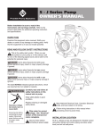
Pool Pumps
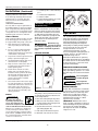
Description
This swimming pool pump is designed for
use with permanently installed pools only.
Unpacking
After unpacking the unit, carefully
inspect for any damage that may have
occurred during transit. Check for
loose, missing or damaged parts.
IMPORTANT
SAFETY
INSTRUCTIONS
Danger indicates
an imminently hazardous situation which, if not avoided,
will result in death or serious injury.
!
DANGER
Warning indicates
a potentially hazardous situation which, if not avoided,
could result in death or serious injury.
! WARNING
Caution indicates a
!
potentially hazardous situation which, if not avoided,
may result in minor or moderate injury.
CAUTION
Notice indicates
important information, that if not followed, may cause
damage to equipment.
NOTICE
READ &
FOLLOW ALL
INSTRUCTIONS
This manual contains information that
is very important to know and understand. This information is provided for
SAFETY and to PREVENT EQUIPMENT
PROBLEMS. To help recognize this
information, observe the following:
1. Read these rules and
instructions carefully.
Failure to follow these
MANUAL
instructions could
cause serious bodily
injury and/or property
damage.
To reduce the risk
of injury, do not
permit children to use this product
unless they are closely supervised at
all times.
SAVE THESE
INSTRUCTIONS DO
NOT DISCARD
This pump is for
use with permanently installed pools. If specified, the
pump may be used with hot tubs and
spas. Do not use with storable pools.
A permanently installed pool is constructed in or on the ground or in a
building such that it cannot be readily
disassembled for storage. A storable
pool is constructed so that it may be
readily disassembled for storage and
reassembled to it’s original integrity.
and away from direct sunlight. The surrounding area should provide protection from the elements and ample
room for maintenance and service.
Ensure the drainage will flow away
from the pump.
Above ground pool pumps are not
self-priming. If suction line valves are
installed, the pump may be located
above water level. Keep the vertical distance from the water level to a minimum. Otherwise, the pump must be
located below filled water level to facilitate priming.
Inground pool pumps are self-priming. Mount pump below water level for
easy priming. If the pump must be
located above the filled water level,
keep the vertical distance to a minimum.
! WARNING
!
CAUTION
! WARNING
Pump only clear water. Do
not pump flammable or
explosive fluids such as
gasoline, fuel oil, kerosene, etc. Do not
use in a flammable and/or explosive
atmosphere. Personal injury and/or
property damage could result.
! WARNING
All wiring must be performed by a qualified electrician. The pump must be
installed in compliance with all local
codes and the National Electrical Code.
2. Do not install within an outer
enclosure or beneath the skirt of
the hot tub or spa, unless so
marked.
Installation
GENERAL PLUMBING
SOLVENT WELD CONNECTIONS
Use rigid or flexible PVC pipe. Ensure
pipe ends are clean and free of any
flash caused by the cutting operation.
Use the proper adhesive for the type of
pipe specified.
RECOMMENDED ADHESIVES*
PVC - PVC Joint
PVC - ABS Joint
Uni-Weld
Pool-Tite 2000
Uni-Weld
Pool-Tite 2000
Suregard Flex 20
Suregard Weld
All No. 5
IPS Weld-On 705
IPS Weld-On 794
LOCATION
!
DANGER
Disconnect, tag and lock out
power source before
attempting to install, service, relocate or perform any maintenance.
Locate pump as close to pool/spa as
possible. Install the pump on a hard,
level surface that is dry, well ventilated
* These recommendations are examples only
and are not intended to restrict brands
NOTE: Use an adhesive primer to
ensure adhesive joints are secure.
Suregard P-3000 has a purple tracer to
qualify in areas where codes specify a
primer must be used.
REMINDER: Keep your dated proof of purchase for warranty purposes! Attach it to this manual or file it for safekeeping.
© 2002 Wayne Water Systems
For parts, product & service information
visit www.waynepumps.com
321700-001 6/02
Operating Instructions and Parts Manual
Installation (Continued)
Consider climatic conditions when
applying adhesives. Atmospheric conditions with high humidity will make the
adhesive action of certain glues less
effective. Follow the manufacturer's
instructions.
THREADED CONNECTIONS
Use only Teflon® tape or equivalent on
threaded plumbing connections. Other
pipe compounds may damage threads.
Do not use silicone or petroleum based
compounds. Do not overtighten. Hand
tightening plus 1/2 turn is sufficient.
PUMP PLUMBING
Suction pipe should be as large or larger
than discharge pipe. Avoid using a suction pipe smaller than pump connection.
1. Keep the piping as straight and
short as possible, and of suitable
size.
2. Do not connect an elbow directly
into the pump inlet. A length of
straight pipe will allow proper entry
of the water to the pump.
3. Slope horizontal runs upward to the
pump to prevent trapping air.
4. Use independent piping supports to
alleviate strain on the pump.
5. Keep as much of the suction line as
possible below the water level to
reduce priming time.
6. Install valves and unions in the
pump suction and return lines to
facilitate servicing. Valves will throttle the pump discharge. Valves are
also essential for pump maintenance if the system is installed
below deck level.
7. Use a check valve in the suction pipe
for inground pumps at or below the
water level if the suction lift is more
than 5 feet or the dry suction is
more than 10 feet long. Keep the
valve in the suction line fully open
during operation.
WIRING
! WARNING
All wiring must be performed by a qualified electrician. The pump must be
installed in compliance with all local
codes and the National Electrical Code.
When motor installation is within 5 ft.
(1.5 m) of the pool’s interior walls, a
solid copper bonding conductor (minimum size No. 8 AWG/8.4 mm2) should
be connected from the accessible wire
connector on the motor.
• to all metal parts of the swimming
pool
• to all electrical equipment
• to metal conduit
• to metal piping within 5 ft. (1.5 m)
of the pool’s interior walls
IMPORTANT: Use copper
conductors only.
115 Volts
230 Volts
HI
LO
Volt
Refer to information on motor nameplate for electrical service data. Install
motors with a fused disconnect switch
or dedicated circuit breaker. Be sure
wire size is sufficient for pump HP and
distance from power source. Install a
ground fault circuit interrupter for
maximum safety.
Disconnect, tag,
and lock out power
source before attempting to install, service, relocate, or perform any maintenance.
!
DANGER
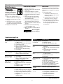
VOLTAGE SELECTOR
L1
HI
LO
Volt
Figure 1b
Operation
Prime pump before attempting to operate. To prime pumps located above water
level, remove strainer cover, fill strainer
body with water then replace cover. If
pump and all piping is located below
water level, the pump will self prime.
After pump has been primed, energize
motor and open all suction and discharge line valves. If no flow is
observed in five minutes, stop the
motor and reprime. If the pump fails to
operate, check for air leaks. Refer to
troubleshooting section.
After about 10 minutes of operation,
check the return fittings for air bubbles.
A continuous flow of air indicates leaks
in the suction line. Locate and correct
any leaks immediately.
CONTROLLING PUMP DISCHARGE
Keep the gate valve in the suction line
fully open during operation. To control
the discharge, use a valve in the return
line.
HI
LO
Volt
!
CAUTION
Do not retighten
strainer Ring-Lok
during operation.
Do not operate
pump with closed
suction or discharge valve.
!
L2
Figure 1a
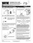
This pump is factory wired for 115 volts.
To change the voltage to 230 volts follow the steps below:
1. Disconnect the pump from power.
2. Remove cover from back of motor
to find voltage selector (Figure 1a).
3. Pull selector knob out.
4. Rotate selector knob to correct voltage setting (Figure 1b).
5. Push selector knob back in place.
6. Reinstall cover to back of motor.
www.waynepumps.com
2
CAUTION
WATER CHEMISTRY
Proper and consistent use of chemicals
is necessary to manage a water system.
Chlorine is the most commonly used
chemical to provide clean, sanitary
water. Daily administration of dry or
liquid chlorine (calcium or sodium
hypochlorite) is essential.
IMPORTANT: Maintain the correct
level of acidity or alkalinity of the pool
water. Readings above pH 7.0 are alkaline. A pH 7.0 is neutral. Readings
below pH 7.0 are acidic. A desirable
range is 7.2 to 7.4.
Operating Instructions and Parts Manual
Maintenance
!
DANGER
Disconnect, tag and lock
out power source before
attempting to install, service, relocate or perform any maintenance.
1. Motors are self-lubricating - no
additional lubrication is required.
2. Clean pool pump strainer of hair
and lint.
3. Visually inspect motor for blockage
of air vents on motor shell. Remove
any debris after shutting off breaker.
4. Replace worn shaft seals.
HAIR AND LINT STRAINER
1. Switch off the power.
2. Close the valves in the suction and
return line.
3. Turn strainer Ring-Lok counterclockwise and remove stainer cover.
4. Lift strainer basket away from the
pump.
5. Clean and reposition the basket
into the pump. Take care to seat
the basket properly.
6. Clean the o-ring and relubricate
with petroleum jelly if necessary.
7. Clean o-ring seats on the cover and
strainer.
8. Refit the cover and strainer RingLok; hand tighten only.
9. Open the valves to return pump to
operation.
!
CAUTION
WINTERIZING
Always protect system from freezing
temperatures. Drain the system if there
is a possibility of freezing. To drain the
system:
1. Units with a filter:
a. Sand filter: Backwash for 3 to 5
minutes and then set dial valve to
winterize position.
b. Cartridge filter: Clean the filter
element and store in dry area.
2. Drain system by loosening drain
plug. The drain plug does not have
to be completely removed.
Removing pipe caps will facilitate
draining also.
Do not retighten
strainer Ring-Lok
during operation.
Troubleshooting Chart
Symptom
Possible Cause(s)
Symptom
Possible Cause(s)
Motor does not
start
1. Disconnect switch or circuit breaker
in OFF position
2. Fuses blown or thermal overload open
3. Locked motor shaft
4. Motor windings burned out
5. Defective starting switch inside single-phase motor
6. Disconnected or defective wiring
7. Low voltage
Low pump capacity
(continued)
6. Dirty filter
7. Impeller clogged
8. Wrong rotation (3 phase only)
Low pump pressure
1. Pump running at reduced speed (see
previous)
2. Wrong rotation (three phase models
only)
3. Discharge valve or inlet fittings
open too wide
Motor does not
reach full speed
1. Low voltage
2. Motor windings connected for wrong
voltage on dual voltage model
High pump pressure
Motor overheats
(protector trips)
1. Low voltage
2. Motor windings connected for wrong
voltage on dual voltage model
3. Inadequate ventilation
1. Discharge valve or inlet fittings
closed too much
2. Return lines too small
3. Dirty filter
Noisy pump and
motor
1. Plugged basket in skimmer or hair in
lint strainer
2. Worn motor bearings
3. Valve in suction line partly closed
4. Suction line partly plugged
5. Vacuum hose plugged or too small
6. Pump not supported properly
Leakage of water
at shaft
Shaft seal requires replacement
Air bubbles at inlet
fittings
1. Leakage of air into suction line at
connections or valve stem
2. Cover gasket around hair and lint
strainer needs cleaning
3. Restriction in suction line
4. Low water level in pool
Pump does not
deliver water
1. Pump is not primed
2. Closed valve in suction or discharge
line
3. Leakage or air into suction system
4. Impeller clogged
Low pump capacity
1. Valve in suction or discharge line
partly closed
2. Suction or discharge line partly plugged
3, Suction or discharge line too small
4. Pump running at reduced speed (see
previous)
5. Plugged basket in skimmer or hair
and lint strainer
www.waynepumps.com
3
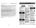
Pool Pumps
Operating Instructions and Parts Manual
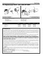
For Replacement Parts, call 1-800-237-0987
3
1
1
2
2
3
Replacement Parts Illustration for
Models WIP100 and WIP150
Replacement Parts Illustration for
Models WAP75 and WAP100
Please provide following information:
- Model number
- Serial number (if any)
- Part description and number as shown in parts list
Ref.
No. Description
Address parts correspondence to:
Wayne Water Systems
100 Production Drive
Harrison, OH 45030 U.S.A.
Part Number for Models:
WAP75
WAP100
WIP100
WIP150
1
Pump kit
69006-001
69007-001
69004-001
69005-001
Qty.
1
2
Shaft seal kit
21009-001
21009-001
21009-001
21009-001
1
3
Motor kit
32023-001
32023-002
69000-001
69001-001
1
Limited Warranty
For one year from the date of purchase, Wayne Water Systems ("Wayne") will repair or replace, at its option, for the original purchaser any part or parts of its Sump Pumps or Water Pumps (“Product”) found upon examination by Wayne to be
defective in materials or workmanship. Please call Wayne (800-237-0987) for instructions or see your dealer. Be prepared
to provide the model number and the serial number when exercising this warranty. All transportation charges on
Products or parts submitted for repair or replacement must be paid by purchaser.
This Limited Warranty does not cover Products which have been damaged as a result of accident, abuse, misuse, neglect,
improper installation, improper maintenance, or failure to operate in accordance with Wayne’s written instructions.
THERE IS NO OTHER EXPRESS WARRANTY. IMPLIED WARRANTIES, INCLUDING THOSE OF MERCHANTABILITY
AND FITNESS FOR A PARTICULAR PURPOSE, ARE LIMITED TO ONE YEAR FROM THE DATE OF PURCHASE. THIS IS
THE EXCLUSIVE REMEDY AND ANY LIABILITY FOR ANY AND ALL INDIRECT OR CONSEQUENTIAL DAMAGES OR
EXPENSES WHATSOEVER IS EXCLUDED.
Some states do not allow limitations on how long an implied warranty lasts, or do not allow the exclusions or limitations
of incidental or consequential damages, so the above limitations might not apply to you. This limited warranty gives you
specific legal rights, and you may also have other legal rights which vary from state to state.
In no event, whether as a result of breach of contract warranty, tort (including negligence) or otherwise, shall Wayne or
its suppliers be liable for any special, consequential, incidental or penal damages including, but not limited to loss of profit or revenues, loss of use of the products or any associated equipment, damage to associated equipment, cost of capital,
cost of substitute products, facilities, services or replacement power, downtime costs, or claims of buyer’s customers for
such damages.
You MUST retain your purchase receipt along with this form. In the event you need to exercise a warranty claim, you
MUST send a copy of the purchase receipt along with the material or correspondence. Please call Wayne (800-237-0987)
for return authorization and instructions.
DO NOT MAIL THIS FORM TO WAYNE. Use this form only to maintain your records.
MODEL NO._______________ SERIAL NO.__________________________ INSTALLATION DATE_____________
ATTACH YOUR RECEIPT HERE
www.waynepumps.com
4