1
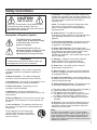
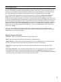
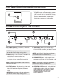
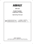
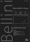
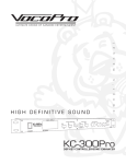
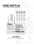
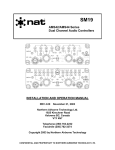
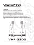
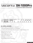
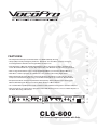
l
a
u
FEATURES:
n
• Two Independent Compressor/Limiter/Gates in a 1RU Roadworthy Housing
a
• Unique (IKC) Circuitry Intelligently Combines 'Hard Knee' and 'Soft Knee' Compression Styles,
Providing Excellent Inaudible and Program Music Compression
m
• Fully Automatic or Manually Variable Attack/Release Times, Compression Ratios and Threshold
Levels Allow Both the Novice and the Experienced User Full Effective Use All Processing Controls
• Dual 12-stage Gain Reduction and 8-stage Input/Output Meters for Accurate, Reliable Metering
• Dual-Mono or Stereo Operation for a Multitude of Live, Studio or Recording Applications
s
• Built-In Adjustable Dynamic Enhancer Selectively Replaces High-End Loss Even During Severe
Compression Produced by High-energy or Low-End Content So Processed Vocals Remain Vibrant
'
• IRC (Interactive Ratio Control) Expander/Gate Automatically Adjusts Expansion Per the Program
Material, Eliminating the Noise Floor During Quiet Sections or Music Pauses
r
• 1/4" and XLR-TRS Input/Outputs Provide for Balanced and Unbalanced Integrations to External Devices
n
e
• Auto-mode Allows for "Hands-Free" Operation of CLG-600, Allowing Users to Focus on Other Aspects of
the Show, Recording or Broadcast
30
-35
-50
0
OFF
27
24
21
18
15
12
-10
-20
-10
9
6
4
2
LEVEL
1
+10
THRESHOLD
dB
EXPANDER/GATE
-30
CH 1
2.5
2.5
-30
20
-10
-5
-3
0
+3
INAUDIBLE GAIN
+5
3
0
-40
+20
THRESHOLD
dB
MANUAL
8
1.5
1
0.1
RATIO
M1
200
msec
OUT
4
.05
AUTO
COMPRESSOR/LIMITER
RELEASE
Sec
-20
+20
OUPUT
dB
MONO
OFF
27
6
IN
ENHANCER
-20
-10
-50
0
OFF
STEREO
MODE
24
21
18
15
12
-10
-20
-35
+10
30
9
6
4
2
LEVEL
1
+
0.5
0
+10
THRESHOLD
dB
EXPANDER/GATE
2.5
-30
+10
-40
CH 2
2.5
-30
20
-10
0.5
-5
-3
0
+3
+5
0
3
0
+20
THRESHOLD
dB
1.5
MANUAL
8
CLG-600
OUT
w
GAIN
+
-
DUAL CHANNEL COMPRESSOR
1
0.1
RATIO
N1
200
msec
.05
AUTO
4
RELEASE
Sec
-20
+20
OUPUT
dB
OFF
6
LIMITER WITH GATE
IN
COMPRESSOR/LIMITER
CLG-600
ENHANCER
Dual Channel Compressor/Limiter with Gate
o
INAUDIBLE
-35
Safety Instructions
CAUTION
RISK OF SHOCK
CAUTION: To reduce the risk of electric shock,
do not remove cover (or back). No userserviceable parts inside. Only refer servicing to
qualified service personnel.
Explanation of Graphical Symbols
The lightning flash & arrowhead
symbol, within an equilateral triangle,
is intended to alert you to the
presence of danger.
The exclamation point within an
equilateral triangle is intended to alert
you to the presence of important
operating and servicing instructions.
WARNING
To reduce the risk of fire or electric shock, do
not expose this unit to rain or moisture.
8. Ventilation - The appliance should be situated so its
location does not interfere with its proper ventilation. For
example, the appliance should not be situated on a bed,
sofa, rug, or similar surface that may block the
ventilation slots.
9. Heat - The appliance should be situated away from
heat sources such as radiators, heat registers,
stoves, or other appliances (including amplifiers)
that produce heat.
10. Power Sources - The appliance should be
connected to a power supply only of the type described
in the operating instructions or as marked on the
appliance.
11. Grounding or Polarization - Precautions should be
taken so that the grounding or polarization means of
an appliance is not defeated.
12. Power-Cord Protection - Power-supply cords
should be routed so that they are not likely to be walked
on or pinched by items placed upon or against them,
paying particular attention to cords at plugs,
convenience receptacles, and the point where they exit
from the appliance.
13. Cleaning - Unplug this unit from the wall outlet
before cleaning. Do not use liquid cleaners or
aerosol cleaners. Use a damp cloth for cleaning.
14. Power lines - An outdoor antenna should be
located away from power lines.
1. Read Instructions - All the safety and operating
instructions should be read before the appliance is
operated.
15. Nonuse Periods - The power cord of the appliance
should be unplugged from the outlet when left unused
for a long period of time.
2. Retain Instructions - The safety and operating
instructions should be retained for future reference.
16. Object and Liquid Entry - Care should be taken so
that objects do not fall and liquids are not spilled into the
enclosure through openings.
3. Heed Warnings - All warnings on the appliance and in
the operating instructions should be adhered to.
4. Follow Instructions - All operating and use
instructions should be followed.
5. Attachments - Do not use attachments not
recommended by the product manufacturer as they may
cause hazards.
6. Water and Moisture - Do not use this unit near water.
For example, near a bathtub or in a wet basement and
the like.
7. Carts and Stands - The appliance should be used
only with a cart or stand that is recommended by the
manufacturer.
7 A. An appliance and cart combination
should be moved with care. Quick stops,
excessive force, and uneven surfaces may
cause an overturn.
17. Damage Requiring Service - The appliance should
be serviced by qualified service personnel when:
A.
B.
C.
D.
The power supply cord or plug has been damaged; or
Objects have fallen into the appliance; or
The appliance has been exposed to rain; or
The appliance does not appear to operate normally
or exhibits a marked change in performance; or
E. The appliance has been dropped, or the enclosure
damaged.
18. Servicing - The user should not attempt to service
the appliance beyond that described in the operating
instructions. All other servicing should be referred to
qualified service personnel.
Note:
To CATV system installer's (U.S.A.): This reminder is
provided to call the CATV system installer's attention to
Article 820-40 of the NEC that provides guidelines for
proper grounding and, in particular, specifies that the
cable ground shall be connected as close to the point of
cable entry as practical.
1
Welcome...
And Thank you for purchasing the CLG-600 from VocoPro, your ultimate choice in Karaoke entertainment!
With years of experience in the music entertainment business, VocoPro is a leading manufacturer of
Karaoke equipment, and has been providing patrons of bars, churches, schools, clubs and individual
consumers the opportunity to sound like a star with full-scale club models, in-home systems and mobile
units. All our products offer solid performance and sound reliability, and to further strengthen our
commitment to customer satisfaction, we have customer service and technical support professionals
ready to assist you with your needs. We have provided some contact information for you below.
1728 Curtiss Court
La Verne, CA 91750
Toll Free: 800-678-5348
TEL: 909-593-8893
FAX: 909-593-8890
VocoPro Company Email Directory
Customer Service & General Information
[email protected]
Tech Support
[email protected]
Remember Our Website
Be sure to visit the VocoPro website www.vocopro.com for the latest information on new products,
packages and promos. And while you're there don't forget to check out our Club VocoPro for Karaoke
news and events, chat rooms, club directories and even a Service directory!
We look forward to hearing you sound like a PRO, with VocoPro, your ultimate choice in Karaoke
entertainment.
FOR YOUR RECORDS
Please record the model number and serial number below, for easy reference, in case of loss or theft. These numbers
are located on the rear panel of the unit. Space is also provided for other relevant information
Model Number
Serial Number
Date of Purchase
Place of Purchase
2
Listening For A Lifetime
Selecting fine audio equipment such as the unit you've just purchased is only the start of your musical enjoyment. Now it's
time to consider how you can maximize the fun and excitement your equipment offers. VocoPro and the Electronic
Industries Association's Consumer Electronics Group want you to get the most out of your equipment by playing it at a
safe level. One that lets the sound come through loud and clear without annoying blaring or distortion and, most
importantly, without affecting your sensitive hearing.
Sound can be deceiving. Over time your hearing 'comfort level' adapts to a higher volume of sound. So what sounds
'normal' can actually be loud and harmful to your hearing. Guard against this by setting your equipment at a safe level
BEFORE your hearing adapts.
To establish a safe level:
• Start your volume control at a low setting.
• Slowly increase the sound until you can hear it comfortably and clearly, and without
distortion.
Once you have established a comfortable sound level:
• Set the dial and leave it there.
• Pay attention to the different levels in various recordings.
Taking a minute to do this now will help to prevent hearing damage or loss in the future. After all, we want you listening for
a lifetime.
Used wisely, your new sound equipment will provide a lifetime of fun and enjoyment. Since hearing damage from loud
noise is often undetectable until it is too late, this manufacturer and the Electronic Industries Association's Consumer
Electronics Group recommend you avoid prolonged exposure to excessive noise. This list of sound levels is included for
your protection.
Some common decibel ranges:
Level
30
40
50
60
70
80
Example
Quiet library, Soft whispers
Living room, Refrigerator, Bedroom away from traffic
Light traffic, Normal Conversation
Air Conditioner at 20 ft., Sewing machine
Vacuum cleaner, Hair dryer, Noisy Restaurant
Average city traffic, Garbage disposals, Alarm clock at 2 ft.
The following noises can be dangerous under constant exposure:
Level
90
100
120
140
180
Example
Subway, Motorcycle, Truck traffic, Lawn Mower
Garbage truck, Chainsaw, Pneumatics drill
Rock band concert in front of speakers
Gunshot blast, Jet plane
Rocket launching pad
-Information courtesy of the Deafness Research Foundation
3
CLG-600
Dual Channel Compressor/Limiter with Gate
Contents
Safety Instructions . . . . . . . . . . . . . . . . . . . . . . . . . . . . . . . . . . . . . . . . . . . . . . . . . . . . . . . . . .
1
Welcome . . . . . . . . . . . . . . . . . . . . . . . . . . . . . . . . . . . . . . . . . . . . . . . . . . . . . . . . . . . .
2
Listening for a Lifetime . . . . . . . . . . . . . . . . . . . . . . . . . . . . . . . . . . . . . . . . . . . . . . . . .
3
Features . . . . . . . . . . . . . . . . . . . . . . . . . . . . . . . . . . . . . . . . . . . . . . . . . .
4
Introduction . . . . . . . . . . . . . . . . . . . . . . . . . . . . . . . . . . . . . . . . . . . . . . . . . . . . . . . . . . . . . .
5
Unpacking . . . . . . . . . . . . . . . . . . . . . . . . . . . . . . . . . . . . . . . . . . . . . . . . . . . . . . . . . .
6
AC Power Requirements . . . . . . . . . . . . . . . . . . . . . . . . . . . . . . . . . . . . . . . . . . . . . . . . . . . . . . . . . .
6
Mounting / Installation. . . . . . . . . . . . . . . . . . . . . . . . . . . . . . . . . . . . . . . . . . . . . . . . . . . . . . . . .
6
Front Panel Description and Controls. . . . . . . . . . . . . . . . . . . . . . . . . . . . . . . . . . . . . . . . . . . . . .
Rear Panel Description and Controls . . . . . . . . . . . . . . . . . . . . . . . . . . . . . . . . . . . . . . . . . . . . .
Connections and Cables . . . . . . . . . . . . . . . . . . . . . . . . . . . . . . . . . . . . . . . . . . . . . . . . . . . . . . . . .
Typical Applications . . . . . . . . . . . . . . . . . . . . . . . . . . . . . . . . . . . . . . . . . . . . . . . . . . . .
9
10
10-12
Troubleshooting Tips. . . . . . . . . . . . . . . . . . . . . . . . . . . . . . . . . . . . . . .
13
Useful Compressor Settings. . . . . . . . . . . . . . . . . . . . . . . . . . . . . . . . . . . . . . . .
14
Specifications . . . . . . . . . . . . . . . . . . . . . . . . . . . . . . . . . . . . . . . . . . .
15
CLG-600 FEATURES
• Two Independent Compressor/Limiter/Gates in a 1RU Roadworthy Housing
• Unique (IKC) Circuitry Intelligently Combines 'Hard Knee' and 'Soft Knee' Compression Styles,
Providing Excellent Inaudible and Program Music Compression
• Fully Automatic or Manually Variable Attack/Release Times, Compression Ratios and Threshold
Levels Allow Both the Novice and the Experienced User Full Effective Use All Processing Controls
• Dual 12-stage Gain Reduction and 8-stage Input/Output Meters for Accurate, Reliable Metering
• Dual-Mono or Stereo Operation for a Multitude of Live, Studio or Recording Applications
• Built-In Adjustable Dynamic Enhancer Selectively Replaces High-End Loss Even During Severe
Compression Produced by High-energy or Low-End Content So Processed Vocals Remain Vibrant.
• IRC (Interactive Ratio Control) Expander/Gate Automatically Adjusts Expansion Per the Program
Material, Eliminating the Noise Floor During Quiet Sections or Music Pauses
• 1/4" and XLR-TRS Input/Outputs Provide for Balanced and Unbalanced Integrations to External Devices
• Auto-mode Allows for "Hands-Free" Operation of CLG-600, Allowing Users to Focus on Other Aspects of
the Show, Recording or Broadcast
4
7-9
Introduction
The CLG-600 Compressor/Limiter/Gate was designed for use in the Karaoke community, but of course can also
be used in the multitude of situations that compressors commonly handle. If this is your first experience using a
compressor, or are completely new to the process of compression, limiting and gating, it is well advised to read
this manual thoroughly to best acquaint yourself with them prior to any live application of the CLG-600.
The CLG-600's range of applications can be divided into three basic categories, compressing, limiting and
gating. When used as a protective device to prevent audio levels from overloading systems such as tape
recorders, power amplifiers, speakers, or transmitters, it is generally referred to as 'Limiting'. It may also be used
to even out a Karaoke performance by deliberately reducing the dynamic range (volume range) of the overall vocal
signal, and setting the output gain to bring the compressed signal back to a normalized volume level. Doing this
allows the operator to avoid unexpected volume peaks and secure a much louder and full sounding vocal signal at
the same time. That is referred to as 'Compressing'. Also common, is the application of completely removing
audible noise from low-volume sections of an audio signal, i.e. fans, air conditioning units, electric hums. This is
referred to as 'Gating'.
In any case, the CLG-600 offers exceptional performance and precise controls for the Karaoke and audio
enthusiasts, and with time and experience, you will soon harness the full potential of the CLG-600, never doing
another show or studio recording without it!
Common Compression Terms
• Threshold - Volume level at which the compressor begins compression.
• Ratio - The relative level the volume above threshold will be brought down by.
• Attack & Release - Attack controls how fast the compressor reacts to signals passing over the threshold point.
Release is how quickly it stops reacting once the signal passes under the threshold again.
• Output Gain - Amplifies the signal after it has been compressed to compensate for the reduction in high
volumes.
• Hard Knee or Soft Knee - These are widely used and referred to styles of compression that can smoothen out
threshold point processing, or abruptly apply threshold point processing. Soft Knee compression uses an
"acceptable range" around a particular threshold point, providing a smoother transition. Hard Knee compression
starts exactly at the threshold point, providing razor-like abrupt transitions.
5
Unpacking
As a part of our system of quality control, every Vocopro product is carefully inspected before leaving the factory
to ensure flawless appearance. After unpacking, please inspect for any physical damage. Save the shipping carton
and all packing materials, as they were carefully designed to reduce to minimum the possibility of transportation
damage should the unit again require packing and shipping. With your new CLG-600, you should have received
the following items:
UNPACKING
INAUDIBLE
GAIN
30
-35
24
21
18
15
12
-10
-20
-10
0
OFF
27
9
6
4
2
LEVEL
1
+
-
-35
-50
+10
THRESHOLD
dB
EXPANDER/GATE
-30
CH 1
2.5
2.5
-30
20
-10
-5
-3
0
+3
INAUDIBLE GAIN
+5
3
0
-40
+20
THRESHOLD
dB
MANUAL
8
1.5
1
0.1
RATIO
M1
200
msec
OUT
4
.05
AUTO
COMPRESSOR/LIMITER
RELEASE
Sec
-20
+20
OUPUT
dB
MONO
OFF
30
27
6
IN
ENHANCER
21
18
15
12
9
6
4
2.5
-20
-10
-50
0
OFF
STEREO
MODE
24
-10
-20
-35
+10
2
LEVEL
1
+
0.5
0
+10
THRESHOLD
dB
+10
-40
CH 2
2.5
-30
20
-10
0.5
-5
-3
0
+3
+5
0
3
0
-30
+20
THRESHOLD
dB
EXPANDER/GATE
1.5
MANUAL
8
CLG-600
OUT
DUAL CHANNEL COMPRESSOR
1
0.1
RATIO
N1
200
msec
.05
AUTO
4
RELEASE
Sec
-20
+20
OUPUT
dB
COMPRESSOR/LIMITER
CLG-600
OFF
6
LIMITER WITH GATE
IN
ENHANCER
AC Main's
Power Cable
AC Power Requirements
A standard IEC-320 AC inlet is provided on the rear panel of the CLG-600 to accept the detachable power cord
shipped with the unit. Units are pre-selected for 115 VAC, 60Hz and should be plugged into a standard NEMA 515 3-wire grounded AC receptacle. For use of the unit outside the US, 230VAC, 50-60Hz power supplies are
required. The CLG-600 will perform normally from 100 to 125 VAC. An internal line fuse is used. In the event of
fuse failure, refer to a qualified service technician for servicing. Power consumption is 9 watts.
Mounting Installation
TOP VIEW
Rack Unit with Empty Space
The CLG-600 mounts in a standard 19-inch equipment rack. The mounting screw threads vary with different rack
manufactures and you should refer to your rack instructions for proper hardware. An oval head or flat head screw
with a plastic countersink washer is preferred to protect the finish of the CLG-600 under the screw. The CLG-600
is housed in a rugged steel case and can tolerate "in the field" abuse, however proper care will best suit the unit
for long-life and performance.
1. To mount, carefully place the CLG-600 in the desired rack space.
2. It is recommended to allow at least 4" of space deep in order to make cable connections easily.
3. Make sure all four holes are aligned evenly.
4. Using an alternating "X" rotation, screw mounting bolts in to ensure even tension and alignment.
6
Front Panel Description and Controls
1. POWER button - This button turns the CLG-600's main power ON/OFF.
1
CLG-600
DUAL CHANNEL COMPRESSOR
LIMITER WITH GATE
INAUDIBLE
GAIN
30
-35
24
21
18
15
12
-10
-20
-10
-50
0
OFF
27
9
6
4
2
LEVEL
1
+
-
-35
+10
THRESHOLD
dB
EXPANDER/GATE
-30
CH 1
2.5
2.5
-30
20
-10
-5
-3
0
+3
INAUDIBLE GAIN
+5
3
0
+10
-40
+20
THRESHOLD
dB
8
1.5
1
0.1
RATIO
M1
200
msec
OUT
4
.05
AUTO
COMPRESSOR/LIMITER
RELEASE
Sec
-20
+20
OUPUT
dB
MONO
OFF
27
6
IN
ENHANCER
-20
-10
-50
0
OFF
STEREO
MODE
24
21
18
15
12
-10
-20
-35
MANUAL
30
9
6
4
2
LEVEL
1
+
0.5
0
+10
THRESHOLD
dB
2.5
-30
+10
-40
+20
THRESHOLD
dB
EXPANDER/GATE
EXPANDER/GATE SECTION
2. THRESHOLD control - The THRESHOLD control has a
range of -50dB to +10 dB, allowing applications from low
level compression to high level limiting. The THRESHOLD
control determines the audio level above which
gain reduction occurs.
3. EXPANDER/GATE LED's - These LED's indicate
when EXPANSION or GAIN REDUCTION is occurring
within a signal process. The visual range is from 1 to 30dB.
When the GREEN (-) LED comes on, that means that
GAIN REDUCTION is beginning to occur, due to input signal
peaks exceeding the selected threshold in dB. When the
RED (+) LED comes on, that means that EXPANSION is
beginning to occur, due to the input signal dropouts falling
CH 2
2.5
-30
20
-10
-5
0.5
-3
0
+3
+5
0
3
0
1.5
MANUAL
8
CLG-600
OUT
DUAL CHANNEL COMPRESSOR
1
0.1
RATIO
N1
200
msec
.05
AUTO
4
-20
RELEASE
Sec
+20
OUPUT
dB
OFF
LIMITER WITH GATE
6
IN
ENHANCER
COMPRESSOR/LIMITER
3
INAUDIBLE
+
-
2
-35
-35
-10
-50
0
OFF
+10
THRESHOLD
dB
EXPANDER/GATE
7
Front Panel Description and Controls (cont.)
4. IN/OUT button - This switch enables you to quickly
hear the CLG-600 compressor/limiter IN or OUT of the
audio chain. When the switch is in the OUT position,
all limiting and compression controls and functions
are bypassed, with the exception of the gain and
output controls, which continue to function as
straightforward level controls.
8. RELEASE control - The RELEASE control
determines how fast or slow a compressed
segment returns to its original volume. The
available range is from .05 to 4 seconds. This
control when used correctly creates either a
9. AUTO/MANUAL switch - By activating the AUTO
switch to the ON position, the attack and release
controls are handled by the CLG-600
automatically. When it is set to the MANUAL
position, the attack and release controls will
adhere to settings of the controls in place. This
allows for unobtrusive musical compression with
widely varying dynamics to occur without
"manning" the sound system.
5. THRESHOLD control - The THRESHOLD control
has a range of -40dB to +20 dB, allowing applications
from low level compression to high level limiting. The
THRESHOLD control determines the audio level above
which GAIN REDUCTION occurs. When the
THRESHOLD LED comes on, that means that GAIN
REDUCTION is beginning to occur, due to input signal
peaks exceeding the selected threshold in dB.
11
5
GAIN
30
27
24
21
18
15
12
-10
-20
-30
8
7
6
9
6
4
2
LEVEL
1
CH 1
2.5
2.5
12
10
-30
20
-10
0.5
-5
-3
0
4
+3
+5
0
0
+10
-40
+20
THRESHOLD
dB
MANUAL
8
1.5
1
0.1
RATIO
M1
200
msec
OUT
4
.05
AUTO
RELEASE
Sec
-20
+20
OUPUT
dB
OFF
IN
COMPRESSOR/LIMITER
9
6. RATIO control - This control determines the RATIO
of change in output level to changes in input level
for all signals above threshold. The numbers printed
around the RATIO control are calibrated in dB and
indicate the increase in input (above threshold)
required to produce a 1db increase in output. This
can be expressed conveniently as a ratio. If the
output remains constant no matter how high the
input level, we have an infinite input/output ratio.
NOTE: It should be remembered that the RATIO
control has no effect on signals which are below
threshold. There is a common but incorrect
notion that limiting always implies the use of an
infinite ratio. Although there are times when an
infinite ratio is desirable, there will be situations
where infinite, or "hard", limiting action is neither
appropriate nor necessary.
7. ATTACK control - ATTACK controls how fast the
compressor reacts to signals passing over the
threshold point. The available range is from 0.1 to
200 ms. This control when used correctly creates
either a smooth or abrupt signal process.
8
10. OUTPUT LEVEL control - OUTPUT Level control
is provided to fully cut or restore up to -/+ 20 dB
of system gain. For unity gain, set the control to 0.
NOTE: When the unit is in the BYPASS mode the
output control still functions.
11. GAIN REDUCTION meter - This 8-stage LED
meter indicates the actual GAIN REDUCTION
processing level and displays this in range
of 0-30 dB.
12. LEVEL EXPANSION meter - This 8-stage meter
indicates the actual LEVEL EXPANSION level and
displays this in a range of -30dB to +6dB.
Front Panel Description and Controls (cont.)
Enhancer Section
13
13. PROCESS control - This control sets the
available amount of ENHANCEMENT between
OFF and 6. DYNAMIC ENHANCEMENT allows
you to replenish any high frequencies that may
have become lost during the compression
process. ENHANCEMENT should only be
added when compression is taking place.
3
6
OFF
ENHANCER
Rear Panel Description and Controls
17
14
OUTPUTS
AC INPUT
+ TIP/PIN2
OPERATING
LEVEL
+4dBU
- RING/PIN3
+ SLEEVE/PINT
INPUTS
OUTPUTS
+ TIP/PIN2
+ TIP/PIN2
- RING/PIN3
+ SLEEVE/PINT
- RING/PIN3
+ SLEEVE/PINT
-10dBU
VOLTAGE
SELECTOR
+4dBU
INPUTS
+ TIP/PIN2
- RING/PIN3
+ SLEEVE/PINT
-10dBU
FUSE
CH 1
CH 2
16
OPERATING
LEVEL
15
14. AC POWER terminal - This terminal is where the
MAINS POWER CABLE is connected.
NOTE: Before your power on the unit, make sure
you have the correct voltage setting in place.
15. FUSE housing - This is where the CLG-600's fuse
resides. If for any reason the fuse blows, it is
recommended to seek assistance from a
technician prior to re-installing another fuse, due to
the fact that further damage could occur to the
CLG-600.
18
19
17. AUDIO INPUT jacks - Each channel has an
AUDIO INPUT section. Each AUDIO INPUT section
has an XLR and a ¼" INPUT jack for audio source
connections.
NOTE: The XLR and ¼" input jacks on the same
channel cannot be used simultaneously.
18. AUDIO OUTPUT jacks - Each channel has an
AUDIO OUTPUT section. Each AUDIO OUTPUT
section has an XLR and a ¼" INPUT jack for audio
device connections.
NOTE: If replacing the fuse, ONLY replace with the
same type and rating.
NOTE: The XLR and ¼" input jacks on the same
channel cannot be used simultaneously.
16. VOLTAGE selector - This selector is used to toggle
between 115V and 230V power settings.
Select 115V for a North American based power
setting and 230V for a European based power
setting.
19. OPERATING LEVEL control - Professional-level
audio equipment just about always employs a
+4dBU operating setting, while consumer level
audio equipment tends to employ the -10dBU
setting. This control is used to maintain
compatibility with both "classifications"
of sound equipment.
NOTE: Before your power on the unit, make sure
you have the correct voltage setting in place.
9
Connections and Cables
Balanced vs. Unbalanced Audio Connections
Balanced signal connections are preferred in pro audio applications because of their improved immunity to
induced hum and noise. A properly shielded and wired balanced input stage on any audio product will reject most
unwanted noise (RFI, EMI) picked up by the cable, as well as minimize ground loop problems. Therefore it is
always advantageous to use balanced connections when running signal more than ten or fifteen feet, although
particularly noisy environments may require that even short patch cables be balanced.
Unbalanced connections are used mostly for short distance, high level signals (0dBu nominal). Most external EMI
noise pick-up will be masked under the noise floor of the signal, assuming there is little or no gain following the
unbalanced signal. If a gain stage does follow a signal, or if externally sourced noise persists, use balanced
connectors.
Inputs and Outputs
Your CLG-600 Compressor/Limiter is provided with two different connector types. 1/4" TRS (tip-ring-sleeve) phone
jacks, and three pin XLR connectors will allow interfacing to most professional audio products. TRS balanced
connections use the tip as (+) and the ring as (-) signal, with sleeve used for ground. XLR connectors use pin 2
(+) and pin 3 (-) with pin 1 ground. When possible, we recommend balanced connections between all components
in your system. If inputs are used unbalanced, the signal should be on the (+) connection and the (-) connection
must be tied to ground, or signal loss will result. While a mono phone plug used as an unbalanced connection will
automatically ground the (-) ring of the jack, XLR's will not automatically do this, so attention must be given to
proper wiring.
Typical Applications
The CLG-600 as A Protection Device
The CLG-600 provides quick and accurate gain control for the prevention of sound system overload due to
unexpected peaks/transients. Sound system distortion is usually the result of amplifiers running out of power, in
which case nice round waveforms turn into harsh sounding squared-off waveforms. Looking at it from the
perspective of the speaker diaphragm, this means that, whereas in normal operation the diaphragm is required to
accelerate, slow down, smoothly change direction, and accelerate again, distorted operation requires an instant
acceleration, instant stop, a change of direction, and instant acceleration again.
Since speaker diaphragms are subject to the laws of physics, they won't take this kind of punishment for long. The
diaphragm may shatter, or its voice coil may overheat. In addition to the damaged caused by sustained overload,
the speaker may also be damaged by occasional, one-shot high level overload, for example, the sound of a
microphone falling face-first onto a hardwood floor. Even if this type of transient doesn't destroy a speaker
outright, it may damage the speaker surround in such a way as to cause mechanical abrasion and future failure.
In this situation, Limiting would be used as a protective measure.
Alternatives for Sound System Installations
To install the CLG-600 in a system using a passive crossover, insert it between your mixers output and the power
amplifier input. It may be inserted between the mixer output and the crossover input, in which case it will act on
the entire audio frequency spectrum. Alternately, if the limiter is inserted between an output of the electric
crossover and the input of a power amp, it will only affect a specific band of frequencies.
Compression for Feedback Control
A common practice in sound system setting-up is equalizing the room to remove feedback. This is generally
accomplished by turning up system gain to purposely induce feedback, searching for the center frequency of the
feedback, and then equalizing at that frequency to remove the feedback. Once this frequency has been cut,
system gain is again increased to induce another feedback point, and the whole procedure is repeated until the
engineer is satisfied that the significant problem frequencies have been corrected. The major problem with this
approach is that the feedback can easily get out control, and the engineer ends up dashing back and forth
between the mixer volume controls and the equalizer controls, while everyone in the room plugs their ears and
prays it will end soon. The CLG-600 can turn this procedure into a fast, painless job, eliminating loud feedback
levels and the possibility of speaker or ear damage.
10
Typical Applications (cont.)
Compression for Feedback Control Procedure:
1. Set up the CLG-600 unit's controls as follows:
a. Output level control to -20dB.
b. Input Gain control to 0dB.
c. Threshold control to -30dB.
d. Ratio control to infinity ( )
e. Attack time to 5mS.
f. Release time to 1 sec.
2. Adjust equalizer controls to a flat setting, and if the equalizer has an overall volume control,
boost it by 10 to 15 dB.
3. Open up several microphone input channels to a normal operating level, with typical EQ settings, and turn the
console master fader up to a louder than normal setting. At this point, the system should be well into feedback,
but the room volume will be constant due to the action of the limiter. You can listen to the feedback at any level
you like by simply varying the CLG-600's output level control, although below a certain monitoring level, the
feedback will stop.
4. Try to determine the feedback frequency, and then equalize it by adjusting the center frequency, bandwidth, and
boost/cut controls of your parametric equalizer. (Note: a graphic equalizer can also be used, although with less
accuracy.) After eliminating the problem frequency, try to further define it by sharpening up the bandwidth, reattacking the frequency control, and making the cut shallower, if possible.
5. As soon as the first feedback frequency has been removed, bring up system gain until another feedback point
is induced. Repeat the equalization procedure until it becomes impossible to distinguish individual, predominant
feedback frequencies.
6. Return all mixer, EQ overall gain, and compressor/limiter gain controls to normal settings.
Recording
The limiter can be used to prevent tape saturation in analog recording. Also, with modern trends toward
inexpensive digital recording, it remains necessary to protect against input overload. With digital recording, the
information stored on tape, hard disk, optical disk, etc., is either a 1 or 0, so actual signal level on the tape is not
the concern it is with analog recordings, in fact it is not even a user controllable parameter. What is of concern
however, is the signal level applied to the A-D (analog to digital) converters. If clipping occurs at the converter
input stage, the resulting distortion is most unpleasant, and will be recorded digitally as if they were part of the
original audio signal, forever mixed with the audio. To prevent converter distortion while preserving the extended
dynamic range of digital recording, look up the max input level of your recorder/converter and set up the limiter as
follows:
1. Set Gain to 0.
2. Set Threshold to 2-3 dB below max converter input.
3. Set Ratio to 10.
4. Set Attack to 2 mS.
5. Set Release to .2 Sec.
6. Set Output level to 0.
If you are exceeding threshold frequently, your input signal is probably too high and should be turned down. Of
course, every situation is different, so experimentation before final recording is always a good idea, but this is a
good starting point. To obtain a gentler limiting action at the expense of some dynamic range, decrease the
threshold to -15 and the ratio to 3-5. This is also a good starting point for analog recording.
11
Typical Applications (cont.)
Broadcasting
Compression has long been used as a tool to make an audio signal appear louder. A good example is in
broadcasting, where competing stations with identical transmitters and power attempt to sound louder than each
other. Since they are all restricted with respect to maximum audio level (modulation), their best tactic is to
squeeze the dynamic range of their programs to just a few dB. The audio output level of the station virtually never
changes, and the listener perceives this continuous high-level sound as being louder than the same material in an
uncompressed form. Although both compressed and uncompressed programs reach the same peak levels, the
compressed signal stays near peak level more of the time, and thus sounds louder. This technique makes the
broadcast more intelligible over the road noise in your car, and increases the geographical area over which the
broadcast is audible to the listener. A similar, if less pronounced, effect can be used in sound reinforcement and
recording applications.
SPECIAL EFFECTS
Altering the Texture of Musical Instruments
It would be impossible to mention here all the ways that compression is used to create new sounds with familiar
instruments. Some typical uses are:
1. Creating a "fatter" kick drum or snare sound.
2. "Thickening" acoustic guitars.
3. Adding punch and sustain to electric bass or guitar.
In general, use a gentle compression ratio, say 4:1, with a 10 mS attack time, 0.1 sec. release time, and a
low enough threshold to cause 6 to 10dB of gain reduction. Try using this effect to help bring out a lead
vocal or instrumental solo in a cluttered mix. The compressor is also a great corrective tool when working with
singers whose own dynamic control is less than perfect. A little compression helps to keep their quieter lines
from becoming buried in the mix. Experimentation is highly recommended.
Voice-Over Compression ("Ducking")
The CLG-600 units can be used to automatically reduce music to a background level when an announcer is
speaking. In this scheme, only the music signal is actually gain-reduced by the limiter. However, the detector is
connected to respond to an announcer's voice instead of the music's peaks. Voice-Over compression assumes
you are already using some sort of mixer to combine the music and mic signals. Use the direct out (send) of the
mic channel to feed the detector input on the CLG-600 unit. Note: Be sure to use a mono plug for the CLG-600
Note: Be sure to use a mono plug for the CLG-600 detector input. Then use the threshold
and ratio controls to determine when and by how much the announcer's voice affects the
music level.
Gain Riding
One solution to the noise vs. distortion trade-off is to keep your hand on the level control and manually adjust gain
to suit the program. Indeed, there are times when this approach is entirely satisfactory. However, in most types of
music there are instantaneous, short duration volume peaks, or transients, which would be difficult to anticipate
and impossible to respond to with manual gain riding, you simply could not bring the level down fast enough. In
many situations, this can present real problems. For example, in recording, an extra burst of enthusiasm from a
lead singer might overload the capabilities of your recording tape, causing ragged distortion and necessitating
another take. In sound reinforcement, a sudden burst of energy through the system can blow fuses or even
damage loudspeakers. In addition to the problem of response time with manual gain riding, it also requires your
constant attention, which takes you away from more important jobs. The need for a fast-acting, reliable, automatic
gain control is answered by limiters and compressors.
12
Troubleshooting Tips
Things to remember
Unshielded cables, improperly wired connectors, and cables with broken strands of wire are very common
problems. Use quality cables with quality, correctly wired connectors.
When using heavy compression, background noise is noticeable during quiet sections of the program as defined
in the section on compression, quiet program material is effectively made louder while loud peaks are made
quieter. When the program source is thus raised in volume, its noise floor is also raised in volume by a
proportionate amount. This is not a defect in the Compressor/Limiter, but an unavoidable side effect of the gain
altering process. If the noise becomes a problem, the solutions are to either decrease noise at the program
source, or use less compression.
No Output
Check AC power. Is the power switch on? Check input and output connections - are they reversed? Are you sure
you have an input signal?
Controls Have No Effect
Is the limiter In/Out switch In? Perhaps the ratio control is set too low to produce an audible effect or the input
level is below threshold. Is the threshold LED lighting up? If not, lower the threshold setting or increase the gain.
Do not expect to hear any effect when the input level is below threshold, since the unit is simply a linear amplifier
at those levels.
Excessive Hum or Noise
Hum is often caused by a "ground loop" between components. Try using the suggested balanced input and output
hookups if the other pieces of equipment used in conjunction with the CLG-600 unit have balanced inputs and
outputs. Noise can also be caused by insufficient drive levels. Make sure you are sending a nominal 0 dBV line
level signal to the unit.
13
Useful Compressor Settings
General Use
Compression ratio: 2:1
Threshold: -10 dB
Attack: 1ms
Release: 300 ms (should give a good amount of punch)
Big Radio Voice
Gate: Off
Threshold: -20db
Ratio: 6:1
Attack: Fast
Release: Slow
Output: +10db
Drums
Gate: -30db
Threshold: -15db
Ratio: 4:1
Attack: Fast
Release: Medium
Output: +10db
Input from Microphone to Computer
Gate: Off
Threshold: -15db
Ratio: 3:1
Attack: Fast
Release: Medium Slow
Output: +6db
14
Specifications
AUDIO INPUT
Type RF filtered, servo-balanced input stage
Impedance 60 k Ohms, balanced
Nominal Operating Level -10 dBu to +4 dBu
Max. Input Level +21 dBu balanced and unbalanced
CNR @ 1 kHz >40 dB
DETECTOR INPUT
Type DC de-coupled, unbalanced input
Impedance <20k Ohms
Max. Input Level +20 dBu
AUDIO OUTPUT
Type Electronically buffered output stage<40 Ohms
Impedance <40 Ohms
Max. Output Level +20 dBu
Bandwidth 5Hz to 50 kHz, +0, -1 dB
THD @ +4 dBu 0.05% typ
THD @ -10 dBu 0.1% typ
IMD (SMPTE) @ +10 dBu 0.01% typ
Noise & Hum, Unity Gain >-93 dBu
Noise & Hum, Fully Off>-97 dBu >-97 dBu
Crosswalk @ 20 kHz>-85 dBu >-85 dBu
CMR @ 1kHz> 60 dB >-60 dBu
COMPRESSOR SECTION
Type IKC (Interactive Knee Compressor)
Threshold Variable (-40 to +20 dBu)
Ratio Variable (1:1 to LM)
Attack Variable (0.1 to 200 msec/20dB)
Release Variable (0.05 to 4 sec./20dB)
Output Variable (-20 to +2- dB)
GATE SECTION
Type IRC (Interactive Knee Control)
Threshold Variable (Off to +10 dB)
DYNAMIC ENHANCER SECTION
Type Dynamically controlled frequency correction
Process Variable (Off to 6)
FUNCTION SWITCHES
In/Out Bypass switch
Auto Program-dependent attack and release times
INDICATORS
CLOSE LED indicates onset of the expander gate
8-Element Gain Reduction Meter 1/4/6/10/15/20/30/dB
POWER SUPPLY
Mean Voltages 115V-120V/230V/240V VAC 30-60 Hz
Power Consumption 9 watts
Fuse 320mA (115V)160mA (230V) slow-blow
PHYSICAL
Dimensions 1.74" (H) x 19" (W) x 8.5" (D)
Net Weight 6.6 lbs.
Shipping Weight 9.5 lbs.
For improvement purposes, modifications may be made from time to
time without prior notice. Specifications may differ from those above
15