1
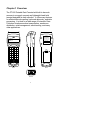
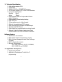
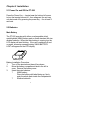
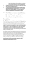
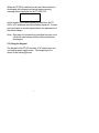
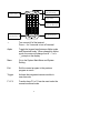
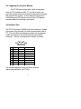
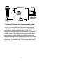
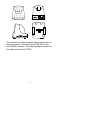
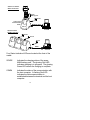
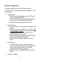
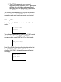
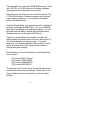
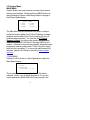
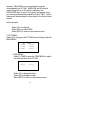
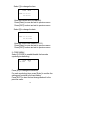
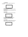
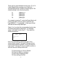
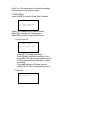
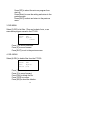
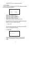
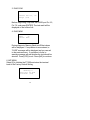
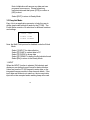
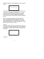
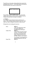
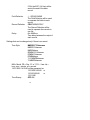
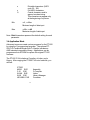
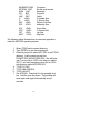
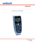
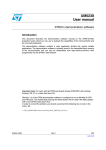
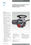
USER’S GUIDE
PORTABLE DATA COLLECTION
TERMINAL
PT-500
DOCUMENT NUMBER: 350500-0010
0
NOTICE
The unit is equipped with a NiMH
battery pack. It is possible that the
customer might receive the battery pack
in a discharged (dead) state due to
product storage. This is normal.
In the above situation, plug the
9V/500mA AC-DC adapter into the PT500
and an available 110V electrical outlet,
switch on the PT500, and fully charge the
NiMH battery pack for 14-16 hours. Or
place the PT500 into the optional charging
cradle for 3 hours before using the unit.
During the initial charging, switching
on the PT500 is highly recommended. In
addition to charging the main NiMH
battery pack, this will also simultaneously
charge up the backup lithium battery.
1
Table of Content
Page
Chapter 1
1.1
1.2
1.3
Overview…...…………………………
Technical Specification………………
Software System……………………..
Application Development…………….
Chapter 2
Installation
2.1
2.2
2.3
2.4
2.5
2.6
Chapter 3
3.1
3.2
3.3
3.4
1
2
2
2
Power On and Off the PT-500………
Batteries……………………………….
Main Battery…………………………..
Backup Battery……………………….
Using the Keypad……………………
Triggering the Scanner Module…….
Interface Port…………………………
Optional Charging Cradle…………..
3
3
3
4
5
6
6
8
Operation………………………..……
Ready Mode………………………….
System Mode…………………………
1. Run Menu………………………….
2. Set Menu…………………………..
3. Dir Menu……………………………
4. Del Menu…………………………..
5. Diag Menu…………………………
6. Init Menu…………………………...
Easy Job Mode……………………….
Application Mode……………………..
11
12
14
14
15
20
20
21
22
23
28
2
Chapter 1 Overview
The PT-500 Portable Data Terminal with built-in barcode
scanner is a rugged, compact and lightweight hand-held
terminal designed for data collection. It offers many features
for efficient barcode reading, keyboard data entry, and data
processing. It is ideal for a wide range of Automatic Data
Collection situations such as transportation, warehouse
distribution, retail management, asset tracking, and many
other applications.
CAUTION
Laser Light - Do
Not Stare Into Beam
670nm Laser Diode
1.0Milliwatt Max Output
Class II Laser Product
Made in Taiwan
PT- 500 V1.0
1024KB Total
996KB Free
>
S/N:500PES0001
Exit
Menu
1
2
A
4
3
B
5
C
6
D
E
7
G
8
H
9
=
0
.
J
+
M
N
/
O
%
I
K
-
*
F
P
$
L
??
Del
Q
#
Enter
(YES)
Bksp
SP
(NO)
Caps
,?
Ins
R
S
T
U
Edit
V
F1
W
F2
X
F3
Y
F4
Z
Alpha
Unitech
Front
Side
Bottom
3
Back
1.1 Technical Specification
??
??
??
??
??
??
??
??
??
??
??
??
??
??
8-bit microprocessor CPU.
64KB ROM.
256KB, 512KB, or 1024KB RAM memory.
32x122 dots graphic LCD, 4 lines x 20 characters.
Low power consumption.
Standby
25mA
Active
160mA
Rechargeable NiMH or 3 disposable AA size
alkaline batteries.
Rechargeable Lithium backup battery.
Real time clock.
36 keys alphanumeric rubber keypad.
Optional integrated laser/CCD scanner.
One good read LED indicator to scanner input.
One standard RS-232 port.
One infrared port communicates to optional cradle.
Optional Cradle for Battery charging and Data
Communication via Local Connection or Modem.
Software System
?? Menu driven user interface
?? Built-in Data Collection Application. (EzJob)
?? Built-in System Management and Data Exchange
Program.
?? Build in diagnostic program
?? Barcode Symbologies:
UPC, EAN, CODE39, I 2 OF 5, CODBAR,
MSI, CODE128 and CODE93.
1.3 Application Development
?? Replaceable EPROM.
?? Application Development Tools Kit for C
programming.
4
Chapter 2 Installation
2.1 Power On and Off the PT-500
Press the Power Key ? located near the bottom left corner
to turn the terminal on and off. As a safeguard, the unit can
only be turned off by pressing the power key ? for at least 3
seconds.
2.2 Batteries
Main Battery
The PT-500 operates with either a rechargeable nickel
metal-hydride (NiMH) battery pack or three standard AA size
alkaline batteries. When the main battery is running low, the
LCD display will start blinking. If the unit is switched off and
on again, a warning message stating “MAIN BATTERY
LOW” will appear on the LCD display.
NiMH Battery Pack
Battery Installation Procedure:
1.
Turn off the terminal and place it face down.
2.
Move the battery compartment latch to the left to
open. Remove the battery cover.
3.
Insert the main batteries:
?
NiMH battery:
Place the battery with label facing up; firmly
push the whole pack inside the compartment.
?
Alkaline batteries:
5
4.
5.
Insert the batteries in the positions as shown
by the polarity symbols inside compartment
Replace the battery cover and move the latch back to
the locked (centered) position.
If you are using NiMH battery pack, please charge
the NiMH batteries continuously for 14 to 16 hours
with AC-DC power adapter, or 3 hours with the
optional charging and communication cradle.
Note: The AC-DC power adapter is only for NiMH battery
pack recharging. It won’t recharge alkaline batteries.
Do not incinerate, crush, or puncture batteries.
Do not dispose of alkaline batteries in fire.
Do not attempt to recharge alkaline batteries.
Backup Battery
The PT-500 also has a built-in rechargeable Lithium backup
battery that temporarily protects data stored in RAM. The
power of the Lithium battery is only consumed when the
main power source is not available, such as when the main
battery is removed or discharged. When a functional NiMH
battery pack or 3 AA-size batteries are in the main battery
compartment, power is provided to backup the RAM
memory and system clock, which effectively puts the Lithium
battery in a standby state.
The power circuitry of the PT-500 monitors the voltage level
from the main power source and automatically connects the
Lithium battery for backup once it has detected that
inadequate power is being provided by the main power
source. Under these conditions, the life of the Lithium
battery would be up to 10 hours. Therefore it is highly
recommended that the main battery always be kept
adequately charged inside the unit.
6
When the PT-500 is switched on and the Lithium battery is
discharged, the following low backup battery warning
message will be displayed on the PT-500 LCD:
BACKUP BATTERY LOW!
In this situation you should upload your data from the PT500 to a PC and have the Lithium battery replaced. Contact
your local sales or service representative for replacement of
the Lithium battery.
Note: Data may not be backed up and data loss may occur
if both the main battery and the Lithium battery are
discharged.
2.3 Using the Keypad
The Keypad of the PT-500 consists of 36 rubber keys and
one large scanner trigger button. The keypad layout is
shown in the following picture.
7
Exit key to
previous menu
Exit
Menu
1
A
2
B
3
C
Enter
(YES)
4
D
5
E
6
F
Bksp
7
G
8
H
9
=
0
K
.
-
??
,?
Del
Q
Ins
R
J
+
M
*
N
/
O
%
Power key to
turn On & Off.
P
$
I
L
#
SP
(NO)
Caps
Go to system menu
and select setting
Integrated scanner
trigger button
Switch to upper &
lower case letter input
Edit
S
T
U
F1
W
F2
X
F3
Y
V
F4
Z
Alpha
Unitech
Switch between Alpha
& Numerical keys
?
Turn on and off of the terminal.
Press ? for 3 seconds to turn off terminal.
Alpha
Toggle the keypad input between Alpha mode
and Numerical mode. When changed to Alpha
mode, the cursor will change from a “?” to a
“_” prompt on the display.
Menu
Go to the System Main Menu and System
Setting.
Exit
Exit the current program to the previous
program or menu.
Trigger
Activate the integrated scanner module to
scan barcode.
F1~F4
Function keys F1 to F4 can be used under the
normal numerical mode.
8
2.4 Triggering the Scanner Module
The PT-500 can be used with a built-in integrated
laser or CCD scanner module. To use the scanner, just
point the scanner window at a barcode and press the trigger
that activates the scanner. A short beep from the buzzer
and flashing red LED indicator on top of the LCD display
indicates when the scanning is successful.
2.5 Interface Port
The PT-500 includes a DSUB-9 pin male connector, located
at the base of the terminal, for serial communication with a
PC. Infra red LEDs and charging contacts for the optional
cradle are located on the bottom right below the DB 9
connector. The pin out assignment is shown as follows:
9
5
Pin
1
2
3
4
5
6
7
8
9
6
1
Signal Direction Description
RXD
TXD
Input Receive
Output Transmitted
GND Reference Ground
RTS
CTS
Output Ready to send
Input Clear to send
The following diagram shows the way to connect
input/output devices to the PT-500.
9
RS232 cable
Exit
Menu
1
A
2
B
3
C
D
7
G
5
E
8
H
6
F
9
0
K
.
-
??
,?
Del
Q
Ins
R
4
=
J
+
M
*
Bksp
SP
I
L
(NO)
MODEM
Caps
N
/
O
P
%
S
$
F1
F2
W
Enter
(YES)
#
T
Edit
U
F3
X
Y
V
F4
Z
Alpha
Unitech
TELEPHONE LINE
MODEM
COMPUTER
SYSTEM
RS-232
PORT
2.6 Optional Charging and Communication Cradle
The PT015 is an optional charging and communication
cradle (docking station) designed to work with the PT-500.
It provides a connection between the PT-500 and a
computer without sacrificing the convenience of portability
for daily usage. The cradle has been incorporated with a
quick-charge circuit for charging the NiMH battery pack
inside the terminal and the spare battery pack on the cradle
simultaneously. Battery charging with the cradle takes only
three hours - in contrast to the 14 hours required by the DC
power adapter.
10
SPARE
COMM
MAIN
RS232
POWER
ON
OFF
DC9V
BACK
FRONT
PT015
RS485
RS232
RS485
SIDE
BOTTOM
The cradle also provides selectable data communication to
the host computer - either point-to-point RS-232 or multipoint RS485 connection. The following diagram shows how
the cradle works with the PT-500.
11
POINT-TO-POINT
RS232 Connection
Exit
Menu
1
A
2
B
3
4
D
5
E
6
7
G
8
H
9
=
0
K
.
J
+
C
F
I
L
Enter
(YES)
Bksp
SP
(NO)
Caps
Spare
Battery pack
M
*
N
/
O
%
P
$
? ?
Del
Q
#
,?
Ins
R
Edit
S
T
U
F1
W
F2
X
F3
Y
V
F4
Z
Alpha
Unitech
DC 9V
Charging and
Communication
Cradle
RS232 cable
PT015
COMPUTER
SYSTEM
MULTI-POINT
RS485 Connection
DC 9V
DC 9V
DC 9V
RS485
interface
COMPUTER
SYSTEM
Four Status Indication LEDs are located at the front of the
cradle:
SPARE
Indicates the charging status of the spare
NiMH battery pack. The glowing Red LED
indicates charging is in progress. The glowing
Green LED means the charging is complete.
COMM
Indicates the status of the communication with
the host computer. A flashing Red LED
indicates the data communication is
established between the terminal and the host
computer.
12
MAIN
Indicates the charging status of the main
battery installed in the PT-500. The glowing
Red LED indicates charging is in progress.
The glowing Green LED indicates charging is
complete.
POWER
When the power is turned on, the glowing
Green LED indicates the cradle is ready to
use.
13
Chapter 3 Operation
The operating system of the PT-500 has 4 different
operating modes for different purposes and functions. They
are as follows:
1. Ready Mode.
?? Keypad Input will be displayed on the LCD and
sent out though RS232 port.
?? Laser or CCD Scanner Input will be displayed on
the LCD and sent out through RS232 port.
?? RS232 Input will be displayed on the LCD.
2. System Mode.
?? Menu will guide you to configure and diagnose the
system.
?? Multi-point protocol is enabled. User may use PT
Comm Manager software to communicate and
exchange files between the PT-500 and PC
through RS232 port or modem.
?? When the terminal is diagnosing itself, Multi-point
protocol will be disabled temporally.
?? Auto Power off is always disabled in System
Mode.
3. EzJob Mode.
?? PT-500 includes a built-in application called
EasyJob, which enables users to define the data
format, collect data, edit data, and upload
collected data to the host computer.
?? Multi-point protocol is disabled under the EzJob
mode.
4. Application Mode.
14
?? The PT-500 can execute user-developed
applications under Application Mode. Applications
will share the configuration settings and files of
the system. After the execution of an application,
the PT-500 returns to the Ready Mode.
The following sections will guide you through the operation
functions and features of the PT-500. They include
descriptions and charts to help you operate your terminal.
3.1 Ready Mode
On starting up the PT-500 for the first time, the LCD will
display:
Sys Error: xxxx
to Reset
Press EXIT & ENTER
This indicates that the memory (RAM) of the PT-500 needs
to be formatted. Press both [EXIT] and [ENTER]
simultaneously to format RAM. The LCD will then display:
All data will be
LOST after reset!
Are you sure? (Y/N)
Note: Once RAM is formatted, all existing data will be lost.
Press [ENTER] for YES or [SP] for NO to confirm your
selection. After RAM is formatted, the system will restart
and display:
PT-500 v1.0
1024KB Total
1012KB Free 15
>
(This example is for units with 1024KB RAM memory. Units
with 128, 256, or 512 KB memory will display messages
appropriate for their respective memory size.)
Hold the power on/off key down for at least 3 seconds. The
PT-500 will shut down. Release the power on/off key and
press it again to power on. You should see the display
return to the Ready Mode.
Under the Ready Mode, your keypad input will be displayed
and sent out through the RS232 port. You can use [BkSp],
[Del], and 2 arrow keys to do simple data editing. You can
also scan barcode labels, and the decoded label will be
displayed and sent out through the RS232 port.
If there is no input activity for more than 3 minutes, the
default setting of the auto power off function will shut the PT500 off automatically to conserve power. To turn this
feature off, or to increase/decrease the time delay for auto
power off, please refer to the System Mode section to
change the system settings.
Default Settings for the Function Keys under Ready Mode
are as follows:
[F1] to enter INPUT Prompt
[F2] to enter CODE MENU
[F3] to enter COMM MENU
[F4] to enter MISC MENU
The purpose of the Function Keys is to provide shortcuts to
access system functions and settings. Please refer to the
System Mode section for the definition of Function Keys
settings.
16
3.2 System Mode
MAIN MENU
System Mode is the main window to access other system
functions and settings. Simply press the [MENU] button on
the right-hand top corner under Ready Mode to change to
the System Mode display.
<
MAIN
1-RUN
3-DIR
5-DIAG
MENU
>
2-SET
4-DEL
6-INIT
The Main Menu has six selections from which to choose.
Under the System Mode, Auto Power Off feature is always
disabled, and the Multi-Point Communication Protocol is
enabled unless specified. You can use the PT Comm
Manager software to configure the system and exchange
data files between PT-500 and PC through RS232 port or
modem. Advanced users can also develop Windows-based
programs to exchange data with PT-500 using DLL files to
work with their programs. For more information about DLL
software, please visit Unitech’s web site at www.unitechadc.com.
1. RUN MENU
Select [1] to Run EzJob or User’s Applications under the
Main Menu window.
<
RUN
MENU
>
1-ezJob
2-MAIN.EXE
(Song Demo v1.00 )
There are two selections to choose from in the above
example. Select 1 to run EzJob program or 2 to run the
user’s application (MAIN.EXE in this case) saved in the
17
terminal. MAIN.EXE is a user application program
downloaded to the PT-500. MAIN.EXE and its internal
name (Song Demo v1.00, which is defined in the
RESOURCE area of user’s C program) will appear only if
you have downloaded the program into the PT-500. EzJob
features will be described in more detail in the EzJob Mode
section.
In this example:
Select [1] to run EzJob.
Select [2] to run MAIN.EXE.
Select [EXIT] to return to the previous menu.
2. SET MENU
Select [2] to configure the PT-500 System Setting under the
MAIN MENU.
<
SET
1-TIME
3-COMM
5-FNKY
MENU
>
2-CODE
4-BEEP
6-MISC
1. TIME MENU
Select [1-TIME] to enter the TIME MENU to adjust
the date and time of the PT-500.
<
SET
1-Time
MENU
>
2-Date
Select [1] to change the time.
Select [2] to change the date.
Select [EXIT] to return to the previous menu.
18
Select [1] to change the time
<
TIME
MENU
>
TIME 00:00:00
XX:XX:XX
Enter the correct time (HH:MM:SS).
Press [Enter] to save and exit to previous menu.
Press [EXIT] to abort and exit to previous menu.
Select [2] to change the date
<
DATE
MENU
>
DATE 00/00/2001
XX/XX/XXXX
Enter the correct date (MM/DD/YYYY).
Press [Enter] to save and exit to previous menu.
Press [EXIT] to abort and exit to previous menu.
2. CODE MENU
Select [2-CODE] to enable/disable the barcode
symbologies decoding.
<
CODE
UPC/EAN
MENU
ON
>
Press [SP] to change the selection.
For each symbology item, press [Enter] to confirm the
setting and continue to the next setting.
Press [EXIT] to abort the last change and exit to the
previous menu.
19
3. COMM MENU
Select [3-COMM] to change the settings of the
RS232 port.
<
COMM
MENU
>
Baud Rate 9600
Press [SP] to change the setting.
Press [Enter] to confirm the setting and continue to
the next selection.
Press [EXIT] to abort the last change and exit to the
previous menu.
4. BEEP MENU
Select [4-BEEP] to adjust the volume of the beep.
<
BEEP
1-None
3-Med
MENU
>
2-Low
4-Hi
Press digit 1 to 4 to select your beep volume.
Press [Enter] to test the selected volume.
Press [EXIT] to return to previous menu.
5. FNKY MENU
Select [5-FNKY] to change the shortcut function key
settings and create user-defined function keys.
<
FNKY
1 - F1
3 - F3
MENU
2 - F2
4 - F4
20
>
There are four user-definable function keys, F1 to F4.
Under Ready Mode, pressing one of them will
automatically perform a series of keypad inputs. The
default settings for the function keys are:
F1
F2
F3
F4
[MENU]111
[MENU]22
[MENU]23
[MENU]26
For example, pressing F1 under the Ready Mode, will
perform the same as if you were to press the four
keys [MENU] 1 1 1 sequentially. In this case, EzJob
will start and will accept data input.
Select 1 to 4 to select the corresponding function key
and enter the keystroke sequence. For example,
typing 1 will select function key F1. Then enter the
desired keystrokes.
<
FNKY
MENU
Define F1
?111
>
.
Note: Any pressed key will become part of the
shortcut input except F1 through F4 because those
shortcut keys cannot be nested. During the shortcut
input, keys F1 through F4 are only used to confirm or
abort the shortcut settings and/or exit.
F1 Reset settings to Factory Default
F2 Clear the fields for new input
F3 Abort any changes and Exit
F4 Save settings and Exit
21
Use F3 or F4 to either abort or confirm the settings
and then return to the previous menu.
6. MISC MENU
Select [6-MISC] to modify Power Auto Features.
<
MISC
MENU
>
1 - Auto PowerOff
2 - Auto Run
Select [1] to change Auto PowerOff feature.
Select [2] to change Auto Run program.
Select [Exit] to return to the previous menu.
1. Auto Power Off
<
MISC
MENU
Auto PowerOff
>
ON
Press [SP] to change the setting.
Press [Enter] to confirm the setting. If Auto
PowerOff is ON, input a delay period from 00
to 30 (minutes) and press [Enter] to confirm
the setting.
The default setting is 03 (three) minutes.
Press [EXIT] to return to the previous menu.
2. Auto Run
<
MISC MENU
Auto Run None
22
>
Press [SP] to select the auto run program from
start up.
Press [Enter] to save the setting and return to the
previous menu.
Press [EXIT] to abort and return to the previous
menu.
3. DIR MENU
Select [3-DIR] to list files. Files can be data, fonts, or an
executable program saved in the PT-500.
<
DIR
MENU
>
EZJOB
TAB
1056
Byte(s)
2-Next
Press [1] to scroll backward.
Press [2] to move forward.
Press [EXIT] to exit to the previous menu.
4. DEL MENU
Select [4-DEL] to delete files from the PT-500.
<
DEL
MENU
EZJOB
TAB
1056
Byte(s)
Delete (Y/N)
>
Press [1] to scroll backward.
Press [2] to move forward.
Press [Del] to delete the file.
Press [YES] to confirm.
Press [NO] to abort the deletion.
23
Press [EXIT] to exit to the previous menu.
5. DIAG MENU
Select [5-DIAG] to diagnose the PT-500 to determine if there
are any hardware problems.
<
DIAG
1-LCD
3-COM
MENU
>
2-KBD
4-MEM
Select [1] to diagnose LCD
Select [2] to diagnose Keypad
Select [3] to diagnose RS232 port
Select [4] to diagnose Memory
Select [Exit] to return to the previous menu
Note: Multi-Point Protocol will be disabled temporally
while the system is diagnosing itself.
1. DIAG LCD
The LCD will become clear, then black, and then will
return to the Diag Menu display.
2. DIAG KBD
<
DIAG
MENU
>
Key Pressed:
_
Keypad input will be displayed on the bottom left
corner. Press [Exit] key to return to the previous
menu.
24
3. DIAG COM
<
DIAG
MENU
>
Connect Pin 2-3, 7-8
Ready? (Y/N)
Before diagnosing, loop back the RS232 port Pin 2-3,
Pin 7-8, and press [ENTER]. The test result will be
displayed on the bottom line.
4. DIAG MEM
<
DIAG MENU
Bank:
00
Offset: F800
>
During diagnosis, Memory Bank and Offset values
will be displayed. If no problem is encountered, a
“PASS” message will be displayed and you can exit
to the previous menu. If a problem is found, a
warning message will ask whether the test should be
aborted. Press [YES] to exit. Press [NO] to continue.
6. INIT MENU
Select [6] to Initialize the PT-500 and return the terminal
back to the Factory Default Setting.
<
INIT MENU
>
Warning!!!
Data will be LOST
Continue? (Y/N)
25
Note: Initialization will remove any data and user
programs from memory. Please upload any
important data and then press [YES] to confirm or
[NO] to abort.
Select [EXIT] to return to Ready Mode.
3.3 EasyJob Mode
Easy Job is an application generator to help the user to
define simple data collection tasks for the PT-500. The
EzJob Menu consists of 4 selections for different functions
and settings.
<
ezJob
Menu
>
1-INPUT 2-DUMP
3-PURGE 4-FORMAT
Note: the Multi-Point protocol is disabled under the EzJob
Mode.
Select [1] INPUT for data collection
Select [2] DUMP to upload data to PC
Select [3] PURGE to erase data
Select [4] FORMAT to define the EzJob data format
Select [Exit] to return to the Ready Mode
1. INPUT
When the INPUT function is selected, EzJob starts and
displays a pre-defined record format for data collection.
Users may use the PT-500 keypad to enter data, or the
integrated scanner module to scan barcode labels. If the
input data and fields do not match up, the incorrect data
input will not be accepted and a warning beep will sound.
26
Left-arrow, right-arrow, and backspace keys can be used for
editing.
Prompt 1
????????????????????
????????????????????
During data input, the user can browse the input data, insert
one new record, or delete one existing record. In order to
edit data, press [EDIT] under the INPUT prompt, use the
arrow keys to move forward or backward, press [INS] to
insert one new record, or press [DEL] to delete one existing
record.
Note: One record may consist of more than one field of
data. Insert and Delete functions treat each record as a
whole unbreakable entity. Press [EDIT] in order to modify
only the selected field in the current displayed record. Press
[EXIT] to return to the previous menu.
2. DUMP
Output the collected data through the RS232 port according
to the data format. While sending data, the LCD display will
be refreshed. A beeping sound indicates the download has
completed.
Dump
0
Done!
3. PURGE
27
Purge Data can be used to delete all the data records after
uploading data to the PC. The PURGE feature will delete all
the data records but still retain the data format.
Purge
30
Sure? (Y/N)
Press [YES] to confirm or [NO] to abort. The second line
number is the number of data records currently in memory.
A beep will sound after the purge is completed.
4. FORMAT
The FORMAT feature defines the data collection input
format. Some settings can be changed at any time - while
others can only be changed if there are no data records.
Settings that can be changed at any time:
Echo
Head of File
End of File
OFF/ON
If ON, each field will be output
through the RS232 port
immediately after data input.
OFF/ON
If ON, Header information will be
sent first. The Header includes
the file name and current time
stamp. EasyJob's file name is
EZJOB followed by three spaces.
Time Stamp's format depends on
the setting selected by the user.
OFF/ON
28
If ON, the EOF (1A Hex) will be
sent at the end of the data
record.
Field Delimiter
Record Delimiter
Delay
, / ; /SPACE/NONE
The Field Delimiter will be used
to separate the fields in each
record.
CRLF/NONE/CR/LF
The Record Delimiter will be
used to separate the records in
one file.
0 to 9999 ms
Time delay between the output of
each record.
Settings that can be changed only if there is no record:
Time Style
MMDDYYYYhhmmss
MMDDYYhhmmss
MMDDhhmm
DDMMYYYYhhmmss
DDMMYYhhmmss
DDMMhhmm
YYYYMMDDhhmmss
YYMMDDhhmmss
MM = Month, DD = Day, YY or YYYY = Year. hh =
hour, mm = minute, ss = second.
12/31/2000 14:20:40 will be presented as
12312000142040 or
123100142040
or
12311420
Time Stamp
OFF/ON
29
If ON, each record will include a
time stamp automatically
following the data record. The
time stamp format will follow the
setting defined by Time Style.
1 to 16
Data input fields are numbered 1
through 16 (maximum). Each
field will have its own Prompt,
Picture, Min, and Max.
Prompt will display the message
prompting data input.
Picture is a sequence of
characters that verifies the data
format.
Min is the minimum length of the
field.
Max is the maximum length of
the field.
Field
Prompt
1 to 20 printable characters.
Displays a message prompting
the user to input data.
Picture
Following are the available
picture characters:
Picture
a
n
p
l
u
Description
Only alpha characters are
accepted. A-Z, a-z
Only digits 0-9, -, and +.
Only digits 0-9.
Only lower-case alpha
characters. a-z.
Only upper-case alpha
characters. A-Z.
30
x
Printable characters. (ASCII
code 32 - 126)
Full ASCII characters.
Control character used to
append constant string.
This character can appear only
at the beginning of a picture.
z
%
Min
>=1, <=Max
Minimum length of data input.
Max
>=Min, <=40
Maximum length of data input.
Note: Bold characters represent the default setting for each
parameter.
3.4 Application Mode
Advanced users can create custom programs for the PT-500
by using the C programming language. The optional PT500 C Kit Technical Binder with C compiler includes an
ANSI standard compatible Library. Applications can be
programmed into EPROM to replace the original PT-500
firmware.
The PT-500 C Kit includes a Compiler, a Linker, and a
Library. After copying the PT-500 C Kit onto hard disk, you
will find:
\PT500
A8051 EXE
C-51 EXE
XLINK EXE
XLIB EXE
HEX2BIN EXE
Assembly
C-Compiler
Linker
Library Manager
Converter
31
MAININFO COM
SETENV BAT
ASM
BAT
C51
BAT
LNK BAT
H
<DIR>
C
<DIR>
R03 <DIR>
S03 <DIR>
XCL <DIR>
APP <DIR>
LST <DIR>
MAP <DIR>
Converter
Set the environment
Assembly
Compiler
Linker
C Header files
C Source files
Object & Lib files
Assembly files
Cross files
C-Source files
List files
Map files
The following steps illustrate how to create an application
under the MS-DOS operating system:
1. Select PT500 as the current directory.
2. Type SETENV to set the environment.
3. Create a project file called APP.PRJ in the PT500
directory. It will contain one text line:
R03\APP.R03 R03\APPRES.R03. We will have
one C source file in <APP> sub-directory called
APP.C, and one Assembly source file in <S03>
sub-directory called APPRES.S03.
4. TYPE C51 APP.
5. TYPE ASM APPRES.
6. TYPE LNK APP.
7. Get APP.BIN. Download it to the portable and
run. Hold the scan key down. The portable will
scan again and again automatically every 3
seconds.
32