1
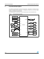
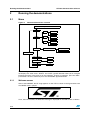
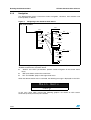
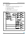
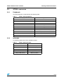
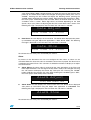
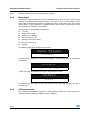
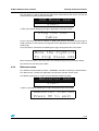
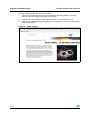
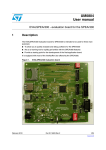
UM0238
User manual
STR91x demonstration software
Introduction
This document describes the demonstration software running on the STR910-EVAL
evaluation board, which you can use to evaluate the capabilities of the microcontroller and
the on-board peripherals.
The demonstration software contains a main application divided into various smaller
applications. The demonstration software is already stored in the embedded flash memory
of the microcontroller and can also be downloaded from http:\\www.st.com\mcu then
programmed into the STR91x internal flash.
Important note: For users with old STR9-eval boards having STR9 MCU with marking
showing "ES_D" or a value less than 618:
Revision 1.2 of the STR9 demonstration software is configured to run at 96 MHz for CPU
and FMI clock. This implies that pressing the Reset button will not restart the MCU (please
refer to the STR9 errata sheet v2.0).
In order to correct this problem, you should uncomment the following line of code in the
main.c file.
//SCU_FMICLKDivisorConfig(SCU_FMICLK_Div2);
October 2006
Rev 2
1/20
www.st.com
Contents
STR91x demonstration software
Contents
1
Functional description . . . . . . . . . . . . . . . . . . . . . . . . . . . . . . . . . . . . . . . 3
1.1
Power control . . . . . . . . . . . . . . . . . . . . . . . . . . . . . . . . . . . . . . . . . . . . . . . 4
1.2
Clocking . . . . . . . . . . . . . . . . . . . . . . . . . . . . . . . . . . . . . . . . . . . . . . . . . . . 4
1.3
Reset control . . . . . . . . . . . . . . . . . . . . . . . . . . . . . . . . . . . . . . . . . . . . . . . 4
1.4
Development and debugging . . . . . . . . . . . . . . . . . . . . . . . . . . . . . . . . . . . 4
1.5
Displays and input devices . . . . . . . . . . . . . . . . . . . . . . . . . . . . . . . . . . . . . 4
1.6
2
1.5.1
LCD . . . . . . . . . . . . . . . . . . . . . . . . . . . . . . . . . . . . . . . . . . . . . . . . . . . . . 4
1.5.2
LEDs . . . . . . . . . . . . . . . . . . . . . . . . . . . . . . . . . . . . . . . . . . . . . . . . . . . . 5
1.5.3
Joystick . . . . . . . . . . . . . . . . . . . . . . . . . . . . . . . . . . . . . . . . . . . . . . . . . . 5
Interfaces . . . . . . . . . . . . . . . . . . . . . . . . . . . . . . . . . . . . . . . . . . . . . . . . . . 5
1.6.1
CAN . . . . . . . . . . . . . . . . . . . . . . . . . . . . . . . . . . . . . . . . . . . . . . . . . . . . . 5
1.6.2
Ethernet . . . . . . . . . . . . . . . . . . . . . . . . . . . . . . . . . . . . . . . . . . . . . . . . . . 5
1.6.3
RS232 . . . . . . . . . . . . . . . . . . . . . . . . . . . . . . . . . . . . . . . . . . . . . . . . . . . 5
1.6.4
Infrared data access (IrDA) . . . . . . . . . . . . . . . . . . . . . . . . . . . . . . . . . . . 5
1.7
Motor control . . . . . . . . . . . . . . . . . . . . . . . . . . . . . . . . . . . . . . . . . . . . . . . 6
1.8
Miscellaneous peripherals . . . . . . . . . . . . . . . . . . . . . . . . . . . . . . . . . . . . . 6
1.8.1
10-bit analog to digital converter . . . . . . . . . . . . . . . . . . . . . . . . . . . . . . . 6
1.8.2
Push-buttons . . . . . . . . . . . . . . . . . . . . . . . . . . . . . . . . . . . . . . . . . . . . . . 6
1.8.3
Audio . . . . . . . . . . . . . . . . . . . . . . . . . . . . . . . . . . . . . . . . . . . . . . . . . . . . 6
Running the demonstrations . . . . . . . . . . . . . . . . . . . . . . . . . . . . . . . . . . 7
2.1
2.2
Menu . . . . . . . . . . . . . . . . . . . . . . . . . . . . . . . . . . . . . . . . . . . . . . . . . . . . . 7
2.1.1
Welcome screen . . . . . . . . . . . . . . . . . . . . . . . . . . . . . . . . . . . . . . . . . . . 7
2.1.2
Navigation . . . . . . . . . . . . . . . . . . . . . . . . . . . . . . . . . . . . . . . . . . . . . . . . 9
Clock sources . . . . . . . . . . . . . . . . . . . . . . . . . . . . . . . . . . . . . . . . . . . . . . 11
2.2.1
2.3
2.4
2/20
Clock control . . . . . . . . . . . . . . . . . . . . . . . . . . . . . . . . . . . . . . . . . . . . . 11
STR91x resources . . . . . . . . . . . . . . . . . . . . . . . . . . . . . . . . . . . . . . . . . . 12
2.3.1
Peripherals . . . . . . . . . . . . . . . . . . . . . . . . . . . . . . . . . . . . . . . . . . . . . . . 12
2.3.2
Interrupts . . . . . . . . . . . . . . . . . . . . . . . . . . . . . . . . . . . . . . . . . . . . . . . . 12
Demo applications . . . . . . . . . . . . . . . . . . . . . . . . . . . . . . . . . . . . . . . . . . 13
2.4.1
Calendar . . . . . . . . . . . . . . . . . . . . . . . . . . . . . . . . . . . . . . . . . . . . . . . . 13
2.4.2
Wave player . . . . . . . . . . . . . . . . . . . . . . . . . . . . . . . . . . . . . . . . . . . . . . 15
2.4.3
USB mouse demo . . . . . . . . . . . . . . . . . . . . . . . . . . . . . . . . . . . . . . . . . 15
STR91x demonstration software
2.4.4
3
Contents
Webserver demo . . . . . . . . . . . . . . . . . . . . . . . . . . . . . . . . . . . . . . . . . . 16
Revision history . . . . . . . . . . . . . . . . . . . . . . . . . . . . . . . . . . . . . . . . . . . 18
3/20
Functional description
1
STR91x demonstration software
Functional description
The STR91x microcontroller evaluation board provides a development and demonstration
platform for STR91x-based applications. It is designed to allow you to try out the major
functions of the STR91x microcontroller.
The following picture summarizes the main functional blocks of the evaluation board:
Figure 1.
Evaluation board overview
Power supply
and Reset
ETM
ETM
JTAG
JTAG
SPI 64Mbit
Serial Flash
ADC
TIM(PWM)
SSP0
CAN
RS232
Transceiver with
full modem
control support
UART0
connector
DB9male
UART1
DB9male
connector
3.3V CAN
Transceiver
DB9male
connector
UART0
STR91x
UART1
MII
PHY
RJ45
connector
USB ESD
protection
USB type B
connector
IrDA
Transceiver
USB
RS232
Transceiver
UART2
DB9male
connector
UART2
Induction Motor
Control connector
RTC 32KHz
Crystal
4/20
Audio
circuit
MC
RTC
Tamper
Graphic LCD
module
GPIO
Joystick
Extention
connector for
total 80 GPIOs
STR91x demonstration software
1.1
Functional description
Power control
STR910-EVAL evaluation board is designed to be powered by a 5V DC power supply. You
can configure the evaluation board to use any of the following three power sources:
●
5V DC power adapter connected to the power supply jack (marked CN2, or PSU for
Power Supply Unit on the silk screen).
●
5V DC power with 500mA limitation via the USB type-B connector (marked CN3, or
USB on the silk screen).
●
5V DC power from the daughter board extension connectors (marked CN5 and
CN6, DTB for Daughter Board on the silk-screen).
For more details, please refer to the power supply section on the STR910-EVAL Evaluation
Board user manual.
1.2
Clocking
Four clock sources are available on STR910-EVAL evaluation board for the microcontroller,
USB, RTC and Ethernet PHY transceiver:
1.3
●
X1- 25 MHz crystal for the STR91xF microcontroller
●
X2- 32 kHz crystal for the embedded RTC
●
X3- 25 MHz crystal for Ethernet PHY transceiver U15
●
U12- 48 MHz oscillator for USB
Reset control
The reset signal of STR910-EVAL evaluation board is low active.
The reset sources include:
●
Power On Reset from STM1001 (U7)
1.4
●
Reset button (PB2)
●
Debugging tools via the CN9 or CN7 connector
●
Daughter board via the CN6 connector
Development and debugging
The STR910-EVAL evaluation board supports connection to both In-Circuit Emulators (ICE)
via a 20-pin standard JTAG interface (CN9) and Trace tools via a 38-pin Embedded Trace
Macrocell (ETM) interface (CN7).
1.5
Displays and input devices
1.5.1
LCD
32x122 graphic LCD display connected to GPIOs.
5/20
Functional description
1.5.2
STR91x demonstration software
LEDs
4 general purpose LEDs are available as display devices.
1.5.3
Joystick
4-direction joystick with selection key.
1.6
Interfaces
1.6.1
CAN
The STR910-EVAL evaluation board supports CAN2.0A/B compliant CAN bus
communication based on a 3.3V CAN transceiver. Both High-speed mode and slope control
mode are available and can be selected by setting a dedicated jumper.
1.6.2
Ethernet
The STR910-EVAL supports IEEE-802.3-2002 compliant Ethernet communication via the
MII interface PHY transceiver (STE100P) with PHY address 10101b and an integrated RJ45
connector with embedded transformer.
1.6.3
RS232
The STR91x evaluation board (STR910-EVAL) provides three on-board RS232 serial ports.
Two channels, UART1 and UART2, use one RS232 transceiver U14.
UART0 uses the RS232 transceiver U13 with full modem control support.
All these RS232 ports are terminated by three male DB9 connectors.
1.6.4
Infrared data access (IrDA)
An on-board IrDA transceiver is available on U9 and the UART1 channel can be configured
to support IrDA communications.
6/20
STR91x demonstration software
1.7
Functional description
Motor control
STR910-EVAL evaluation board supports inductor motor control via a 34-pin connector,
which provides all required control and feedback signals to and from motor power-driving
board.
1.8
Miscellaneous peripherals
1.8.1
10-bit analog to digital converter
●
1.8.2
Varistor: ADC channel6 connected to an on-board variable resistor. The variable
resistor provides a voltage in the range 0 to 3.3V.
Push-buttons
The following push-buttons are provided:
1.8.3
●
KEY: user push-button
●
TAMPER: push-button used to simulate a tamper event on the RTC
Audio
The STR910-EVAL evaluation board supports both audio (*.wav format) recording and
playback.
7/20
Running the demonstrations
STR91x demonstration software
2
Running the demonstrations
2.1
Menu
Figure 2.
Demonstration menus structure
ST Logo + OSIRIS wave
Help
Time
Time Adjust
Time Show
Calendar
Date
Date Adjust
Date Show
Alarm
Alarm Adjust
Alarm Show
Wave Player
OSIRIS
Play / Replay
Stop
Main Menu
CAN Loop Back
Start
USB Mouse Demo
Start
Webserver Demo
Start
The above figure shows the menu system of the STR91x demonstration. The column to the
left displays the main menu. "RIGHT" and "LEFT" joystick direction allow you to navigate
between the items in the menu or in the sub-menu. To enter a sub-menu, press the "SEL"
push-button. To exit a sub-menu press the "UP/DOWN" joystick direction.
2.1.1
Welcome screen
After a board RESET, the ST Logo appears on the LCD as shown in the figure below and
the OSIRIS wave is played.
Then, after two seconds, the Welcome message is displayed on the LCD screen as follows:
8/20
STR91x demonstration software
Running the demonstrations
Welcome to the
STR91x Demo vX.X
After two seconds, the following graphic is displayed on the LCD screen:
To Skip
Push SEL
Then press "SEL" to enter in the main menu and displays the first menu item "Help".
If no SEL pressed the main menu is shown automatically after seven seconds.
Note:
When the board is powered up for the first time, you have to set the date and time in the
"Calendar" menu.
9/20
Running the demonstrations
2.1.2
STR91x demonstration software
Navigation
The demonstration menu is based on circular navigation, sub-menu, item selection and
back capability as follows:
Figure 3.
Navigating in the demonstration menus
WELCOME SCREEN
1st LEVEL
2nd LEVEL
LEFT
RIGHT
LEFT
RIGHT
item 1
RIGHT
LEFT
LEFT
L
...
item n
SE
RIGHT
...
SEL
...
LEFT
item 1.2
item 2
UP/DOWN
RIGHT
SEL
item 1.1
SEL
RIGHT
LEFT
...
item 1.n
item 2.1
UP/DOWN
RIGHT
LEFT
item 2.2
RIGHT
LEFT
...
item 2.n
The user navigates using the joystick push-buttons: “RIGHT”, “LEFT”, “SEL”, “UP” and
“DOWN” located on the evaluation board.
●
“RIGHT” and “LEFT” push-buttons perform circular navigation in the current menu
items
●
“SEL” push-button selects the current item
●
“UP” and “DOWN” jumps to the higher level menu.
When the demonstration menu is activated, the following message is displayed on the LCD:
Main menu
Help
In this case, when "SEL" pressed the following graphics are shown on LCD screen
continuously one by one every two seconds.
10/20
STR91x demonstration software
Running the demonstrations
Enter To
Sub-Menu
SEL
SEL
To Exit
Sub-Menu
SEL
Scroll
Sub-Menu
UP
DOWN
LEFT
RIGHT
To exit from this help menu press any joystick push-buttons.
11/20
Running the demonstrations
STR91x demonstration software
2.2
Clock sources
2.2.1
Clock control
The STR91x internal clocks are derived from an on-board 25 MHz crystal source.
In this demo application, the system clock is configured as follow:
●
HCLK frequency is set to 96 MHz
●
FMICLK frequency is set to 96 MHz
●
PCLK is set to 48 MHz
●
USB clock (CK_USB) is set to 48 MHz (internal clock)
Only the RTC is clocked by a 32 kHz external oscillator.
Figure 4.
Clock control
X1_CPU
MAIN
OSC
X2_CPU
MII_PHYCLK
4 to 25 MHz
fOSC
HCLK
APBDIV
(1,2,4,8)
PCLK
1/2
Peripheral
FMICLK
FMICLK Clock
to Flash Memory
Gating
Interface
RCLKDIV
RCLK
(1,2,4,8,16,1024)
25 MHz
PHYSEL
MCLKSEL
fOSC
fMSTR
fPLL
PLL
fRTC
X1_RTC
X2_RTC
RTC
OSC
32.768
kHz
Peripheral HCLK
Clock
to AHB
Gating
peripherals
AHBDIV
(1,2,4)
Peripheral PCLK
Clock
to APB
Gating
peripherals
to RTC
to WDG (software
selectable in WDG
register)
Special interrupt
mode control
CPUCLK
to CPU
BRCLK
1/2
16-bit prescaler
EXTCLK_T0T1
16-bit prescaler
EXTCLK_T2T3
1/2
USB_CLK48M
12/20
Baud rate clock to UARTs
Peripheral
TIM01CLK
Clock
to TIM0 & TIM1
Gating
Peripheral
TIM23CLK
Clock
to TIM2 & TIM3
Gating
Peripheral
48 MHz USBCLK
Clock
to
USB block
Gating
STR91x demonstration software
2.3
STR91x resources
2.3.1
Peripherals
Running the demonstrations
All used peripherals are described on the following table:
Table 1.
2.3.2
STR91x demo peripherals
Used peripherals
Application
FMI
Main
VIC
Main
WIU
Main
GPIO
All applications
SCU
All applications
RTC
Calendar
TIM
Wave player, LEDs show and System timer
CAN
Loop Back communication
USB
USB mouse demo
ENET (DMA/MAC Controller)
Ethernet webserver demo
Interrupts
The following table shows all the enabled interrupts
Table 2.
STR91x demo interrupts
Interrupts
Used for
EXTIT3 IRQ channel
JoyStick and KEY push-button
RTC IRQ channel
Calendar (Alarm)
TIM0 IRQ channel
Wave player
TIM2 IRQ channel
System timer
USB_LP IRQ channel
USB mouse demo
13/20
Running the demonstrations
2.4
STR91x demonstration software
Demo applications
The following section provides a detailed description of each part of the demonstration.
Notes:
2.4.1
●
In the demonstration, the core runs at HCLK = 96 MHz.
●
Red LEDs: LD2, LD3, LD4 and LD5 are always blinking.
Calendar
The STR91x has an embedded Real Time Clock (RTC) which provides a set of continuously
running counters that can be used, with suitable software, to implement a clock-calendar
function. The counter values can be written to set the current time of the system.
This sub-menu is used to configure some miscellaneous functions such as time, date and
alarm.
Time
This sub-menu is divided in two items allowing the user to display or to adjust the current
time.
●
Time Adjust: After the evaluation board is powered up for the first time, the user has to
select this sub-menu to change the default time (00:00:00) to the current time. Once
"Time Adjust" is selected, the first digit of the hour field is ready to be changed.
Pressing the "UP" button will display the current value plus one. Pressing the "DOWN"
button will display the previous digit value. After choosing the digit value press "SEL",
the cursor jumps automatically to the next digit. When all the time digits are set, the
"Calendar" menu is shown. Some digit values are limited to a range of values
depending on the field (hour, minute or seconds). The following message (with the
default time or the current time) is displayed on the LCD when this sub-menu is
selected:
Time Adjust
HH:MM:SS
●
Time Show: this item displays the current time or the default time. The following
message is displayed on the LCD when this sub-menu is selected:
Time Show
HH:MM:SS
To exit from this sub menu, press the UP/DOWN push buttons.
Date
This sub-menu is divided in two items allowing the user to display or to adjust the current
date.
●
14/20
Date Adjust: This item has to be selected after each power-up in order to set the
current date. The user is asked to fill the current date to be stored in the application
memory. The date is displayed on 8 digits: Dayname MM DD YYYY. The default date
STR91x demonstration software
Running the demonstrations
value “SUN JAN 01 2006” is displayed when you enter this menu for the first time after
power-up. The month field is ready to be changed. To change the month, press "UP" or
"DOWN". Pressing the "UP" button will display the following month, pressing the
"DOWN" button will display the previous month. After choosing the month press "SEL",
the cursor jumps automatically to the next field. When all the date fields are set, the
"Calendar" menu is shown. Some digit values are limited depending on the field
(month, day or year). When re-adjusting the date, the current date value is shown. The
following message is displayed on the LCD when this sub-menu is selected:
Date Adjust
SUN JAN 01 2006
●
Date Show: this item displays the current date. The default date displayed after power
up and before using the Adjust item application is “SUN JAN 01 2006”. The following
message is displayed on the LCD when this sub-menu is selected:
Date Show
SUN JAN 01 2006
To exit from this sub menu press UP/DOWN push buttons.
Alarm
By means of this Sub-menu the user can configure the time when an alarm can be
activated. When the alarm time value is reached the alarm wave is played. The Alarm wave
is loaded in the internal Flash. This sub-menu is divided in two items to display or to adjust
the current Alarm.
●
Alarm Adjust: the alarm adjust is reached by the same procedure as the Time and
Date Adjust Submenu. The first digit of the day field is ready to be changed. Pressing
the "UP" button will display the current day value plus one. Pressing the "DOWN"
button will display the previous day value. After choosing the needed day press "SEL",
the cursor jumps automatically to the next field.
Alarm Adjust
DD/HH:MM:SS
●
Alarm Show: this item displays the current alarm time. The default Alarm displayed
after power up and before using the Adjust item application is 01/00:00:00. The
following message is displayed on the LCD when this sub-menu is selected:
Alarm Show
01/00:00:00
To exit from this sub menu press UP/DOWN push buttons.
15/20
Running the demonstrations
STR91x demonstration software
Note:
When an alarm is occurred the Alarm wave is played.
2.4.2
Wave player
The STR91x microcontroller has several embedded Timers which can be used for timing
purposes and generating the output signals. In this case, we use 2 Timers (TIM) the first
Timer TIM3 is configured to generate a PWM signal with a tunable duty cycle. The second
Timer TIM0 is used to generate an Update interrupt every 45.35 µs (22.05 KHz) which
correspond to the TIM3 Duty cycle update.
The wave file has the following characteristics:
●
*.wav file
●
Audio Format: PCM
●
Sample rate: 22050 Hz
●
Bits Per Sample: 8 bits
●
Number Of Channels: Mono
There is one wave to play:
●
OSIRIS
The following message is displayed on the LCD:
Wave Player
OSIRIS
You can re-play a wave only by selecting "Play/Replay". The following message is displayed
on the LCD:
OSIRIS
Play/Replay
If "SEL" pressed, The following message is displayed on the LCD:
OSIRIS
STOP
To stop playing press "SEL" or wait until the end of the wave and the MCU will stop it
automatically.
2.4.3
USB mouse demo
The STR91x microcontroller provides an USB (Universal Serial Bus) which provide an
interface between a full-speed USB bus and the AHB bus.
16/20
STR91x demonstration software
Running the demonstrations
This sub-menu is used to configure the USB cell to communicate with the PC and run the
mouse demo using the joystick push-buttons.
USB Mouse Demo
Start
If "SEL" pressed the following message is displayed on the LCD screen:
Plug the USB
Cable
For this sub-menu you have to connect an USB cable between the USB connector type B
(CN3) and the PC. The previous message will remain displayed on the LCD screen until the
cable plugin.
Once the cable is connected, the following message is displayed on the LCD screen:
Move the JoyStick
To Stop Press SEL
Move the joystick and the PC cursor will move corresponding to the joystick push-button.
To exit from this sub-menu press "SEL".
2.4.4
Webserver demo
The STR91x microcontroller provides a DMA/MAC controller for Ethernet communication.
This demo shows a webserver application, based on the uIP v0.9 TCP/IP stack.
The following sub-menu is used to start the Ethernet webserver demo:
Webserver Demo
Start
If "SEL" is pressed the following message is displayed on the LCD screen:
Webserver Started
Press UP to exit
17/20
Running the demonstrations
STR91x demonstration software
In order to test the webserver demo you need to:
1.
Connect the STR9-EVAL board to your PC Ethernet port using either a crossover
Ethernet cable or through an Ethernet switch or hub.
2.
Change your PC IP address to: 192.168.0.x (where x is a value other than 8)
3.
Connect to the STR9 webpage by typing http://192.168.0.8 in a browser. The following
page should appear:
Figure 5.
18/20
STR9 webpage
STR91x demonstration software
3
Revision history
Revision history
Table 3.
Document revision history
Date
Revision
Changes
15-May-2006
1
Initial release
10-Oct-2006
2
Addition of new section, 2.4.4: Webserver demo
Important note on page 1 added for old STR9 eval boards
19/20
STR91x demonstration software
Please Read Carefully:
Information in this document is provided solely in connection with ST products. STMicroelectronics NV and its subsidiaries (“ST”) reserve the
right to make changes, corrections, modifications or improvements, to this document, and the products and services described herein at any
time, without notice.
All ST products are sold pursuant to ST’s terms and conditions of sale.
Purchasers are solely responsible for the choice, selection and use of the ST products and services described herein, and ST assumes no
liability whatsoever relating to the choice, selection or use of the ST products and services described herein.
No license, express or implied, by estoppel or otherwise, to any intellectual property rights is granted under this document. If any part of this
document refers to any third party products or services it shall not be deemed a license grant by ST for the use of such third party products
or services, or any intellectual property contained therein or considered as a warranty covering the use in any manner whatsoever of such
third party products or services or any intellectual property contained therein.
UNLESS OTHERWISE SET FORTH IN ST’S TERMS AND CONDITIONS OF SALE ST DISCLAIMS ANY EXPRESS OR IMPLIED
WARRANTY WITH RESPECT TO THE USE AND/OR SALE OF ST PRODUCTS INCLUDING WITHOUT LIMITATION IMPLIED
WARRANTIES OF MERCHANTABILITY, FITNESS FOR A PARTICULAR PURPOSE (AND THEIR EQUIVALENTS UNDER THE LAWS
OF ANY JURISDICTION), OR INFRINGEMENT OF ANY PATENT, COPYRIGHT OR OTHER INTELLECTUAL PROPERTY RIGHT.
UNLESS EXPRESSLY APPROVED IN WRITING BY AN AUTHORIZED ST REPRESENTATIVE, ST PRODUCTS ARE NOT
RECOMMENDED, AUTHORIZED OR WARRANTED FOR USE IN MILITARY, AIR CRAFT, SPACE, LIFE SAVING, OR LIFE SUSTAINING
APPLICATIONS, NOR IN PRODUCTS OR SYSTEMS WHERE FAILURE OR MALFUNCTION MAY RESULT IN PERSONAL INJURY,
DEATH, OR SEVERE PROPERTY OR ENVIRONMENTAL DAMAGE. ST PRODUCTS WHICH ARE NOT SPECIFIED AS "AUTOMOTIVE
GRADE" MAY ONLY BE USED IN AUTOMOTIVE APPLICATIONS AT USER’S OWN RISK.
Resale of ST products with provisions different from the statements and/or technical features set forth in this document shall immediately void
any warranty granted by ST for the ST product or service described herein and shall not create or extend in any manner whatsoever, any
liability of ST.
ST and the ST logo are trademarks or registered trademarks of ST in various countries.
Information in this document supersedes and replaces all information previously supplied.
The ST logo is a registered trademark of STMicroelectronics. All other names are the property of their respective owners.
© 2006 STMicroelectronics - All rights reserved
STMicroelectronics group of companies
Australia - Belgium - Brazil - Canada - China - Czech Republic - Finland - France - Germany - Hong Kong - India - Israel - Italy - Japan Malaysia - Malta - Morocco - Singapore - Spain - Sweden - Switzerland - United Kingdom - United States of America
www.st.com
20/20