1
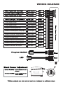
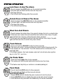
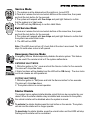
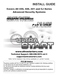
INSTALL GUIDE
430 and 440 Series Vehicle Security Systems
WWW.ULTRASTARTERS.COM
Technical Support 866-698-5872 ext 0
[email protected]
FCC/ID Notice
This device complies with Part 15 of the FCC rules. Operation is subject to the following conditions:
(1) This device may not cause harmful interference, and
(2) This device must accept any interference received, including interference that may cause
undesired operation.
CAUTION: Changes or modifications not expressly approved by the part responsible for compliance
void the user’s authority to operate this devise.
TABLE OF CONTENTS
Table Of Contents
Wiring Diagram
Installation Tips
Pre-Installation Suggestions
Installation Suggestions
Mounting The Module
Installing The LED
Installing The Program Button
Under Hood Connections
Mounting The Siren
Wire Connectors
14 Pin Main Harness Connector
4 Pin Red Connector- Keyless Entry
2 Pin Connector Red- Plug-in LED
2 Pin Blue Connector- Plug-in Program Button
3 Pin White Connector- Aux. outputs
4 Pin White Connector- Addition sensor input
Installation
Basic Installation - Quick start
Shock Sensor Adjusting
Test The System
Programming
Program Overview
Quick View Programming
System Reset
Operations
Transmitter Programming
Battery Replacement
Other Features
System Service Mode
Service Mode- By remote
Diagnostics
Page 2
Page 3
Page 4
Page 5
Page 6-7
Page 7-9
Page 10
Page 11
Page 12
COMPONENTS
- Three Button Remote transmitter’s (430 Series)
- Four Button Remote transmitter’s (440 Series)
- Plug-in Valet Switch (Program Switch)
- 10 Pin Main Harness
- 2 pin Keyless Entry harness
-Control Module
- Plug-in Led
- Multi-Tone Siren
- Installation Guide
- Owners Manual
WIRING DIAGRAM
*500ma negative output
(-) When Armed
Orange
*500ma negative output
Trunk Release
Gray
Connect to vehicles ignition wire
Ignition Input
Yellow
Connect to constant power. 20amp input
12 Volt Input
Red
Connect to Siren wire. 2amp Maximum
Siren Output
Brown
Connect to chassis ground
Ground Input
Black
Connect to door pin. (+) when opened
Door Input
Purple
Connect to door pin. (-) when opened
Door Input
Green
Connect to hood and / or trunk pin
Hood Input
Blue
10 Pin Connector
White
Orange
Grey
Yellow
RedMain
Brown
Black
Purple
Green
Blue
(+) Park lights
(-) When Armed
(-) Trunk Release
Ignition Input
Power Input
(+) Siren Output
Ground Input
(+) Door Input
(-) Door Input
(-) Hood Input
Park light output.
Negative output when system is armed.
Negative output for trunk release. 500ma max.
Input from vehicles ignition wire.
Constant 12 Volt input.
Positive output for siren.
System ground input.
Positive door pin switch input.
Negative door pin switch input.
Negative input from hood pin switch.
3 Pin Connector Red
Green
Door Lock
Door Lock Output - *Programmable
12 Volt Output Output for voltage inverter. Low Current Only
Blue
Door Unlock
Door Unlock Output - *Programmable
Recommended Installation Procedures
Mounting the module- Never mount the module in the engine compartment. Select a
location under the dash to install the main module. Be certain that the module is securely
attached and does not obstruct any serviceable areas. Mount the module so that it cannot
be seen if looking under the dash as it could be easily unplugged by a thief. The module
must be free from all moving parts.
Installing the LED- Choose a location that will be highly visible when the LED is installed.
Most vehicles are equipped with knock out panels in the dashboard, these panels are easily
removable and can be easily replaced if necessary. Once the location is picked, use drill bit
and drill a hole through the panel. Test fit the LED into the hole. Plug the Led into the Red
connector on the main module.
Installing the Program Button- Choose a location to mount the Program Button. This
location should be hidden and not visible from outside the vehicle. Once the location of the
switch is picked, use a 1/4” drill bit and drill a hole. Remove the nut and push the Program
Button through the hole. Replace the nut and tighten until the switch is secure. Plug the
Program Button into the Blue connector of the main module.
Under Hood Connections- Route the hood pin (optional) and Siren wire through the
firewall, into the engine compartment. Always try to pull the wires through a factory rubber
grommet. If drilling through the firewall, BE CAREFUL. Check for obstructions on both sides
of the firewall. After drilling use a snap in grommet to protect the wires from sharp edges.
Mounting the Siren- Choose a location in the engine compartment that is away from
high heat sources and direct exposer to water. The siren should be mounted as well as
grounded to solid metal. Run the wiring for the siren so that it can not be seen or reached
from below the vehicle.
BASIC INSTALLATION
Step 1 - Connect All Of the Following Wires
10 Pin Power Connector
Black
Ground Input
System ground input.
Yellow
Ignition Input
Input from vehicles ignition wire.
Red
Power Input
Constant 12 Volt input.
Brown
(+) Siren Output Positive output for siren.
White
(+) Park lights
Positive park light output.
Green*
(-) Door Input
Negative door pin switch input.
Purple*
(+) Door Input
Positive door pin switch input.
*Test for door pin type (+ or -) then connect the appropriate wire (Green or Purple)
Step 2- Plug-In The Module
When all the connections are done, the control module can be plugged in. Before
connecting the control module, make sure the ignition is in the OFF position. Plug in the
main harness then any other connectors that were used.
Step 3- Test And Adjust The Shock Sensor
To test the Shock Sensor.
1. Press the Lock button once to arm the system.
2. Wait five seconds then impact the vehicle. Lighter impacts to the vehicle should trigger
the warn away (The siren will chirp three times). A harder impact to the vehicle will trigger
the full alarm.(The siren will activate for 60 seconds then turn off).
3. To deactivate the alarm when triggered, press the unlock button twice.
To Increase The Sensitivity.
Turn the adjustment screw Clockwise 1/4 turn then re-test the sensitivity. Repeat this
procedure until the sensitivity of the system is at the appropriate level.
** Do not set to sensitive.
To Decrease The Sensitivity.
Turn the adjustment screw Counter Clockwise 1/4 turn then re-test the sensitivity. Repeat
this procedure until the sensitivity of the system is at the appropriate level.
Step 4- Test The System
1. Open all the vehicles windows.
2. Press the Lock button to arm the system.
3. Wait five seconds (or until the dome light goes out) then reach in through a window and
open the door. The alarm will then activate (repeat on all the doors).
4. Test the Shock Sensor again and adjust if necessary.
5. Insure that all additional features are working as intended.
6. If necessary proceed to Program Mode to adjust the programmable outputs.
Your Basic Install Is Complete!
PROGRAM OVERVIEW
Program mode allows you to adjust the settings and options of your system. Your system
has been intelligently designed by installers with years of experience. The system’s default
settings do not require any program changes in most cases. However, this system does
incorporate a advanced programming system with settings that can be easily adjusted
Entering Program Mode
To Enter Program Mode
1) Make sure ignition is in the off position.
2) Within three seconds turn the key ON the OFF.
3) Press and release the Program Button two times.
4) The siren will chirp and the lights will flash once to confirm entering Program Mode.
Note: If unit does not enter Program Mode, turn ignition off and repeat steps 1-3.
** The ignition wire(Yellow) MUST be connected. If it is not connected it will not be possible
to enter the Program Modes.
Changing A Programmable Setting
1) Enter Program Mode As explained above.
2) When in program Mode, change the desired Program Setting by pressing the
transmitter buttons in the following sequences.
***The Systems Default Setting Are Shown In Bold Lettering.
Quick View Programming
Programmable Feature
Shock Sensor Status
Arm / Disarm Chirps
Ignition Auto Locks
Door Lock Pulse Length
Double Pulse Unlock
Door Input / Voltage Sense
Passive / Active Locks
Passive / Active Arming
System Reset
Press Buttons
One Chirp
Two Chirps
#3-#3-#1
Disabled
Enabled
#2-#1-#1
Chirps Off
Chirps On
#1-#3-#2
Off
On
#1-#3-#1
3 Second
.75 Second
#2-#2-#1
Two Pulses Single Pulses
#1-#1-#3
Voltage
Door Pin
#3-#2-#2
Active
Passive
#1-#2-#3
Active
Passive
#3-#3-#3
Confirmed by Three Siren Chirps
System Reset
This feature will reset the module to it’s factory programmed default setting. This feature
will not delete transmitter codes from memory.
To Reset The System To Factory Defaults.
1) Turn the ignition key On then Off.
2) Press the Program Button two times. The system will respond with two siren chirps.
3) Press the transmitter buttons in the following order: #3-#3-#3. The system will respond
with three siren chirps to confirm the system has been re-set to factory defaults.
Enter Program Mode
Entering program mode is done by the following steps:
1) Make sure ignition is in the off position.
2) Turn the ignition key ON - OFF, leaving key in the OFF position.
3) Press and release the Valet button two times.
4) The siren will chirp one time to confirm entering program mode.
( If this does not happen, turn ignition off, wait five seconds and repeat steps 1-4).
Passive / Active Arming
To change settings:
1 - Enter Program Mode - (Ignition ON-OFF, followed by Valet 2 times)
2 - Press & release transmitter buttons in the following sequence
#1 - #2 then #3
3 - The siren will respond with the following:
1 Chirp
Active Arming
2 Chirps
Passive Arming
Repeat sequence to change selection
Passive / Active Arming
To change settings:
1 - Enter Program Mode - (Ignition ON-OFF, followed by Valet 2 times)
2 - Press & release transmitter buttons in the following sequence
#3 - #3 then #2
3 - The siren will respond with the following:
1 Chirp
Active Locks
2 Chirps
Passive Locks
Repeat sequence to change selection
Door Lock Timing
To change settings:
1 - Enter Program Mode - (Ignition ON-OFF, followed by Valet 2 times)
2 - Press & release transmitter buttons in the following sequence
#1 - #3 then #1
3 - The siren will respond with the following:
1 Chirp 3 Second Door Locks
2 Chirps 0.75sec Pulses
Repeat sequence to change selection
Ignition Auto Locks
To change settings:
1 - Enter Program Mode - (Ignition ON-OFF, followed by Valet 2 times)
2 - Press & release transmitter buttons in the following sequence
#1 - #3 then #2.
3 - The siren will respond with the following:
1 Chirp
Auto Lock Disabled
2 Chirps
Auto Lock Enabled
Repeat sequence to change selection
Double Pulse Unlock
To change settings:
1 - Enter Program Mode - (Ignition ON-OFF, followed by Valet 2 times)
2 - Press & release transmitter buttons in the following sequence
#2 - #2 then #1.
3 - The siren will respond with the following:
1 Chirp
Double Pulse Unlock
2 Chirps Single Pulse Unlock
Repeat sequence to change selection
Voltage / Door Pin Sensing
To change settings:
1 - Enter Program Mode - (Ignition ON-OFF, followed by Valet 2 times)
2 - Press & release transmitter buttons in the following sequence
#1 - #1 then #3
3 - The siren will respond with the following:
1 Chirp
Voltage Sensing- No Door Pin Connection Needed
2 Chirps
Door Pin- Door Pin Connection Required
Repeat sequence to change selection
Chirp Delete
To change settings:
1 - Enter Program Mode - (Ignition ON-OFF, followed by Valet 2 times)
2 - Press & release transmitter buttons in the following sequence
#2 - #2 then #1
3 - The siren will respond with the following:
1 Chirp
Chirps Disabled
2 Chirps
Chirps Enabled
Repeat sequence to change selection
Shock Sensor Disable
To change settings:
1 - Enter Program Mode - (Ignition ON-OFF, followed by Valet 2 times)
2 - Press & release transmitter buttons in the following sequence
#3 - #3 then #1
3 - The siren will respond with the following:
1 Chirp
Shock Sensor OFF
2 Chirps
Shock Sensor ON
Repeat sequence to change selection
Transmitter Programming
Follow the steps below to program the transmitters to the system s memory
Step 1 - Turn the Ignition key ON then OFF - Leaving Key Off.
Step 2 - Press and release the Program Button twice then press and hold.
Step 3 - The siren will respond with five chirps to confirm Transmitter Program Mode.
Note: If the siren does not respond, repeat Steps1&2
Step 4 - Continue to hold the Program Button and press lock button on each of the
transmitter’s to be programmed(Maximum of 3 Different transmitter codes).
Step 5 - The system will respond with a siren chirp each time a transmitter is programmed.
Exit
- After five seconds the system will exit transmitter program mode automatically.
NOTE: You must program ALL of the transmitters to be used at one time. For the owner’s
security any transmitters not programmed at this time will be erased from memory.
*** This system will store a maximum of three transmitter codes in memory.
Deleting Transmitters
Follow the steps below to permanently delete a transmitter code from the system s memory.
Step 1 - Turn the Ignition key ON then OFF - Leaving Key Off.
Step 2 - Press and release the Program Button twice then press and hold.
Step 3 - The siren will respond with five chirps to confirm Transmitter Program Mode.
Note: If the siren does not respond, repeat Steps1&2
Step 4 - Continue to hold the Program Button and press lock button on only the transmitters
that are intended for use on the system.(*Maximum of 3 Different transmitter codes).
Step 5 - The system will respond with a siren chirp each time a transmitter is programmed.
Exit
- After five seconds the system will exit transmitter program mode automatically.
All previous transmitter code are now deleted from the systems memory.
Basic Transmitter Functions
#1
#3
#2
Button #1- Press and release to arm the alarm and lock the doors.
- Press and hold to activate Panic mode.
- Press and release to deactivate triggered alarm.
#1 #2 Button #2- Press and release to disarm and unlock the doors.
- Press and hold to activate the Trunk Release.
#3
- Press and release to deactivate triggered alarm.
Button #3- Press and hold to activate the Car Finder Mode.
Lock Doors & Arm The Alarm
1.Press & release the LOCK button on the remote transmitter.
2.The park lights will flash and the siren will chirp once.
3.The doors will lock.
4.The LED will start flashing within five seconds.
Unlock Doors & Disarm The Alarm
1.Press & release the UNLOCK button on the remote transmitter.
2.The park lights will flash and the siren will chirp twice.
3.The doors will unlock.
4.The LED will stop flashing.
Silent Arm And Disarm
1.Press & release the button three, then press & release the lock or unlock button.
2.If the doors are locked this will unlock the doors without siren chirps, the park
lights will flash two times to confirm the doors have unlocked.
3.If the doors are unlocked this will lock the doors without siren chirps, the park
lights will flash one time to confirm they have locked.
Trunk Release
3 sec.
1.Press and hold the UNLOCK button for three seconds.
2.The doors will unlock, continue holding the unlock button three seconds. the
Trunk release will then activate. The trunk release will be confirmed by one
park light flash.
3.For safety reasons, the trunk release output will not activate when ignition
key is in the “On” po si t i on .
Car Finder Mode
1. Press and hold the button for two seconds.
2. The system will flash the park lights and chirp the siren five times.
**This feature can help find your vehicle in a crowded parking lot.
Panic Mode
1.Press & hold the LOCK button for three seconds.
2.The park lights will flash and the siren will activate.
PANIC MODE DISABLE
1. Press LOCK button to disable the panic mode and to lock the doors.
2. Press UNLOCK button to disable the panic mode and unlock the doors.
3. Panic Mode will stay activated until disabled by the remote transmitter.
Service Mode
1. The system must be disarmed and the ignition is turned OFF.
2.Press and release the lock and unlock buttons at the same time, then press
and hold the lock button for five seconds.
3.The system will respond with five chirps and park light flashes to confirm
that the system is in Valet mode.
4. The LED will stay ON steady to confirm Valet Mode.
Exit Service Mode
1.Press and release the lock and unlock buttons at the same time, then press
and hold the lock button for five seconds.
2.The system will respond with two chirps and park light flashes to confirm that
the system has exited Valet mode.
3. The LED will turn OFF.
Note: If the LED does not turn off, check that all the door’s are closed. The LED
stays On solid when a door is left opened.
Emergency Service Mode
Emergency Service Mode temporarily disables the alarm system. This feature
can be used if the remote is lost or if the system malfunctions.
ENTERING VALET MODE
1.While the ignition is “On” press and hold the Service button for five seconds.
The siren will chirps five times.
2.Alarm functions will be disabled and the LED will be ON steady. The door-locks
and trunk release are still operational.
EXITING VALET MODE
1.While the ignition is “On”press and hold the Service button for five seconds.
The siren will chirps two times.
2. The system returns to normal operation.
Starter Disable
The system has an optional starter disable output that can be connected by your
dealer. When the starter disable relay is installed and connected to the system,
the vehicle’s starter will be disabled when the system is armed.
To activate the starter disable press the lock button on the remote. The system
will arm and the starter will no longer operate.
To deactivate the starter disable, press the unlock button and the LEDS will stop
flashing and the starter will be re-enabled.
Negative Type Door Locks
Positive Type Door Locks
87
87
87a
86
87a
86
85
85
30
30
5 Wire / Reverse Polarity Type Door Locks
87
87
87a
86
87a
86
85
30
85
30
Negative Park Lights- In some cases the park lights may flash erratically after
installing the negative park light relay. To correct this issue add a diode between the coil
pins of the relay as shown.
Ground
Add IN4001 Diode
as shown
87
87a
White
86
85
30
Negative park light output