1
Transport GX21
B2735
1
2
3
1
2
3
RST
User’s Manual
Document part number: D1577-100
Preface
Copyright
This publication, including all photographs, illustrations, and software, is protected under international copyright laws, with all rights
reserved. Neither this manual, nor any material contained herein,
may be reproduced without written consent of the manufacturer-.
Copyright 2003-4
Version 1.00
Disclaimer
Information contained in this document is furnished by TYAN computer Corporation and has been reviewed for accuracy and reliability
prior to printing. TYAN assumes no liability whatsoever, and disclaims any express or implied warranty, relating to sale and/or use
of TYAN products including liability or warranties relating to fitness
for a particular purpose or merchantability. TYAN retains the right to
make changes to product descriptions and/or specifications at any
time, without notice. In no event will TYAN be held liable for any
direct or indirect, incidental or consequential damage, loss of use,
loss of data or other malady resulting from errors or inaccuracies of
information contained in this document.
Trademark recognition
All registered and unregistered trademarks and company names
contained in this manual are property of their respective owners
including, but not limited to the following.
TYAN, TYAN Tiger i7501R S2735-8M, and Transport GX21 are
trademarks of TYAN Computer Corporation.
Intel, Xeon, and combinations thereof are trademarks of Intel Corporation.
AMI, AMIBIOS, and combinations thereof are trademarks of AMI
Software Incorporated.
Microsoft Windows is a trademark of Microsoft Corporation.
IBM, PC, AT and PS/2 are trademarks of IBM Corporation.
Winbond is a trademark of Winbond Electronics Corporation.
Portable Document Format (PDF) is a trademark of Adobe Corporation.
Federal Communications Commission
Notice for the USA Compliance Information Statement (Declaration of Conformity Procedure) DoC
FCC Part 15: This device complies with part 15 of the
FCC Rules
Operation is subject to the following conditions:
1) This device may not cause harmful interference, and
2) This device must accept any interference received including interference that may cause undesired operation. If this equipment does
cause harmful interference to radio or television reception, which
can be determined by turning the equipment off and on, the user is
encouraged to try one or more of the following measures:
•
•
Reorient or relocate the receiving antenna.
•
Plug the equipment into an outlet on a circuit different from
that of the receiver.
Increase the separation between the equipment and the
receiver.
Consult the dealer on an experienced radio/television technician for
help.
Notice for Canada
This apparatus complies with the Class B limits for radio interference as specified in the Canadian Department of Communications
Radio Interference Regulations. (Cet appareil est conforme aux
norms de Classe B d’interference radio tel que specifie par le Ministere Canadien des Communications dans les reglements d’ineteference radio.)
Notice for Europe (CE Mark) This product is in conformity
with the Council Directive 89/336/EEC, 92/31/EEC
(EMC).
CAUTION: Lithium battery included with this board. Do not puncture,
mutilate, or dispose of battery in fire. Danger of explosion if battery
is incorrectly replaced. Replace only with the same or equivalent
type recommended by manufacturer. Dispose of used battery
according to manufacturer instructions and in accordance with your
local regulations.
ii
About this manual
This manual provides you with instructions on installing your Transport GX21 (B2735), and consists of the following sections
Chapter 1:
Provides an introduction to the Transport GX21 (B2735) bare bones,
packing list, describes the external components, gives tables of key
components, and provides block diagrams of the system.
Chapter 2:
Covers procedures on installing the CPUs, memory modules,
optional PCI card, and hard drives.
Chapter 3:
Covers removal and replacement procedures for pre-installed components.
Appendix:
Provides detailed specifications, maintenance and troubleshooting
procedures, an explanation of BIOS and technical diagrams.
iii
Safety information
Before installing and using the Transport GX21 , take note of the following precautions:
iv
•
•
•
Read all instructions carefully.
•
Only use the power source indicated on the marking label.
If you are not sure, contact the power company.
•
The unit uses a three-wire grounded cable, which is supplied with a third pin to ground the unit and prevent electric
shock. Do not defeat the purpose of this pin. If your outlet
does not support this type of plug, contact an electrician to
replace the obsolete outlet.
•
Do not place anything on the power cord. Place the power
cord where it will not be stepped on.
•
Follow all warnings and cautions in this manual and on the
unit case.
•
Do not push objects in the ventilation slots as they may
touch high voltage components and result in shock and
damage to the components.
•
When replacing parts, ensure that you use parts specified
by the manufacturer.
•
When service or repairs have been carried out, perform
routine safety checks to verify that the system is operating
correctly.
•
Avoid using the system near water, in direct sunlight, or
near a heating device.
•
Cover the unit when not in use.
Do not place the unit on an unstable surface, cart or stand.
Do not block the slots or openings on the unit which are
provided for ventilation.
Table of Contents
Overview
About the Transport GX21 (B2735) ...................................................
Product models....................................................................................
Features ...............................................................................................
B2735G21S2 specifications.............................................................
B2735G21S4H specifications..........................................................
B2735G21U4H specifications .........................................................
Unpacking ...........................................................................................
Box contents ....................................................................................
Accessories ......................................................................................
Opening the box...............................................................................
About the product................................................................................
System front view and front panel...................................................
System rear view..............................................................................
System internal views ......................................................................
1
1
2
2
3
4
5
5
7
8
9
9
10
11
Setting up
Before you begin .................................................................................
Work area.........................................................................................
Tools ................................................................................................
Precautions.......................................................................................
Installing motherboard components ....................................................
Removing the chassis cover.............................................................
Installing CPUs ................................................................................
Installing memory ............................................................................
Installing a PCI card ........................................................................
Installing a hard drive..........................................................................
Installing internal hard drives (B2735G21S2).................................
Installing an IDE hard drive.....................................................
Installing an internal S-ATA hard drive ..................................
Installing an external S-ATA hard drive (B2735G21S4H) .............
Installing an external SCSI hard drive (B2735G21U4H)................
Rack mounting ....................................................................................
15
15
15
16
17
17
18
20
21
25
25
25
27
30
31
34
Replacing pre-installed components
Introduction .........................................................................................
Replacing motherboard components...................................................
Disconnecting all motherboard cables.............................................
Replacing the motherboard..............................................................
Replacing the CD-ROM drive ............................................................
Replacing the slim CD-ROM drive (B2735G21S2)........................
Replacing the CD-ROM drive (B2735G21U4H/B2735G21S4H) ..
39
39
39
42
43
43
45
Replacing the floppy disk drive ..........................................................
Replacing the floppy disk drive (B2735G21S2)..............................
Replacing the floppy disk drive (B2735G21S4H/B2735G21U4H).
Replacing the LED control board .......................................................
Replacing the storage backplane .........................................................
S-ATA backplane (B2735G21S4H) ................................................
Replacing the S-ATA backplane (B2735G21S4H) ................
S-ATA backplane features.......................................................
SCSI backplane (B2735G21U4H)...................................................
Replacing the SCSI backplane (B2735G21U4H)....................
SCSI backplane features ..........................................................
Replacing the power supply ................................................................
Replacing the cooling fans ..................................................................
Cooling fan connections ..................................................................
47
47
48
49
50
50
50
52
53
53
55
56
57
59
Appendix
BIOS....................................................................................................
Introduction......................................................................................
BIOS setup utility ............................................................................
BIOS menu bar ................................................................................
BIOS legend bar...............................................................................
BIOS main menu .............................................................................
BIOS advanced menu ......................................................................
CPU configuration submenu............................................................
IDE configuration submenu.............................................................
S-ATA Port/Primary IDE/Secondary IDE configuration submenu.
Floppy configuration submenu ........................................................
Super I/O configuration submenu....................................................
ACPI settings submenu....................................................................
Advanced ACPI configuration submenu .........................................
DMI event logging submenu ...........................................................
Remote access configuration submenu............................................
USB configuration menu .................................................................
USB mass storage device configuration submenu...........................
Onboard devices configuration submenu ........................................
Hardware monitor submenu.............................................................
Advanced PCI/PnP menu.................................................................
BIOS boot settings menu .................................................................
Boot Settings configuration submenu..............................................
Boot device priority submenu..........................................................
Hard disk submenu ..........................................................................
Removable drives submenu .............................................................
ATAPI CD-ROM drives submenu ..................................................
61
61
61
63
64
65
66
67
69
71
72
73
74
76
78
79
80
82
83
84
86
88
89
91
93
94
95
BIOS security menu.........................................................................
BIOS chipset settings.......................................................................
Northbridge chipset configuration submenu....................................
Southbridge chipset configuration submenu....................................
Intel PCI-64 Hub 2 configuration submenu.....................................
BIOS exit menu ...............................................................................
96
98
99
100
101
102
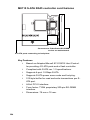
SCSI and S-ATA controller cards.......................................................
Controller card location ...................................................................
M7902 Ultra 320 SCSI controller card features ..............................
M8110 S-ATA RAID controller card features ................................
104
104
105
106
Technical support ................................................................................ 107
Help resources: ................................................................................ 107
Returning merchandise for service .................................................. 107
1.1 About the Transport GX21 (B2735)
Chapter 1: Overview
1.1
About the Transport GX21 (B2735)
Congratulations on your purchase of the Transport GX21
(B2735), rack mountable, barebone system for Intel® Xeon™
processor. The Transport GX21 (B2735) uses an advanced
Intel chipset for optimum performance and reliability. Add-on
S-ATA or SCSI storage controllers provide great flexibility
and combine with Gigabit Ethernet ports to provide powerful
computing capacity and optimal I/O bandwidth for the most
demanding of enterprises.
The rugged, industry standard 19-inch, rack mountable
design contains up to 4 HDD bays, 1 slim CD-ROM bay and 1
3.5-inch FDD, making it both flexible and practical.
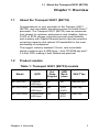
1.2
Product models
Table 1: Transport GX21 (B2735) models
Model
HDD
Hot
Swap
Support
HDD
Backplane
SKU TYpe
B2735G21S2
2 internal
HDD bays
No
NA
Standard SKU
B2735G21S4H
4 removable
HDD bays
Yes
4 port
S-ATA
OEM Only
B2735G21U4H
4 removable
HDD bays
Yes
4 port
SCSI
OEM Only
Chapter 1: Overview
1
1.3 Features
1.3
Features
1.3.1 B2735G21S2 specifications
Enclosure
Storage
•
•
•
•
•
•
•
•
Integrated dual channel IDE controller from ICH5R
2 Integrated S-ATA ports from
ICH5R (RAID 0,1 support)
2 Internal (fixed) HDD bays
Slim 24x CD-ROM drive
Optional 3.5 inch FDD
Processors
Cooling
•
•
•
•
•
•
•
Dual mPGA604 socket
Single or dual Intel® Xeon™ processor with 512K iL2 and 1 MB iL3
533/400 MHz FSB
5 cooling fans(40 x 40 x 28 mm)
1 power supply fan
2 CPU heatsinks
Hardware auto fan speed control
Chipset
Motherboard
•
•
•
•
•
Intel® E7501 server chipset
MCH + ICH5R + P64H2 + FWH
Winbond W83627HF super I/O
chip
analog device ADM 1027 hardware monitoring IC
•
•
•
Tyan Tiger S2735G3NR-8M motherboard
ATX form factor
Award BIOS 8.0 on 8 Mb LPC
flash ROM
LAN remote boot (PXE) support
and SMBIOS v2.3
Memory
Networking
•
•
•
•
•
128-bit dual channel memory bus
6 DDR DIMM sockets
Up to 12 GB DDR266/200SDRAM
Support for registered ECC type
memory modules
•
2 Gigabit Ethernet ports (Intel®
82546EB LAN controller)
1 10/100 Mbps LAN port (Intel®
82551QM controller)
Expansion slots
Power supply
•
•
(1) 64-bit/133 MHz PCI-X slot on
riser card
EPS 12V, 1U, 400W with PFC
Back I/O ports
Video
•
•
•
•
•
•
Stacked PS/2 mouse and keyboard ports
2 USB 2.0 ports
1 9-pin UART serial port
3 RJ-45 LAN ports
1 VGA port
•
ATI® Rage™ XL PCI Graphics
controller
8 MB frame buffer video memory
Front panel
Regulatory
•
•
•
•
2
Industry standard, 19” rack mountable, 1U chassis
2 internal access 1” HDD bays, 1
slim CD-ROM bay, 1 bay for 3.5”
FDD or internal access 1” HDD
21.5 x 17 x 1.7 inch (547 x 432 x
43 mm)
2 USB 2.0 ports
IDE activity, LAN activity, and
power LEDs
Power and reset switches
•
FCC class B (declaration of
conformity)
CE (declaration of conformity)
Chapter 1: Overview
1.3 Features
1.3.2 B2735G21S4H specifications
Enclosure
Storage
•
•
•
•
Industry standard, 19” rack mountable, 1U chassis
4 external access HDD bays, 1
slim CD-ROM bay, 1 slim FDD bay
21.5 x 17 x 1.7 inch (547 x 432 x
43 mm)
•
•
•
•
Integrated dual channel IDE controller from ICH5R
Tyan M8110 4-port S-ATA RAID
card (RAID 0,1, 0+1)
4 hot-swap S-ATA HDD bays
Slim 24x CD-ROM drive
Slim FDD
Processors
Cooling
•
•
•
•
•
•
•
Dual mPGA604 socket
Single or dual Intel® Xeon™ processor with 512K iL2 and 1 MB iL3
533/400 MHz FSB
5 cooling fans (40 x 40 x 28 mm)
1 power supply fan
2 CPU heatsinks
Hardware auto fan speed control
Chipset
Motherboard
•
•
•
•
•
Intel® E7501 server chipset
MCH + ICH5R + P64H2 + FWH
Winbond W83627HF super I/O
chip
analog device ADM 1027 hardware monitoring IC
•
•
•
Tyan Tiger S2735G3NR-8M motherboard
ATX form factor
Award BIOS 8.0 on 8 Mb LPC
flash ROM
LAN remote boot (PXE) support
and SMBIOS v2.3
Memory
Networking
•
•
•
•
•
128-bit dual channel memory bus
6 DDR DIMM sockets
Up to 12 GB DDR266/200SDRAM
Support for registered ECC type
memory modules
•
2 Gigabit Ethernet ports (Intel®
82546EB LAN controller)
1 10/100 Mbps LAN port (Intel®
82551QM controller)
Expansion slots
Power supply
•
•
(1) 64-bit/133 MHz PCI-X slot on
riser card
EPS 12V, 1U, 400W with PFC
Back I/O ports
Video
•
•
•
•
•
•
Stacked PS/2 mouse and keyboard ports
2 USB 2.0 ports
1 9-pin UART serial port
3 RJ-45 LAN ports
1 VGA port
•
ATI® Rage™ XL PCI Graphics
controller
8 MB frame buffer video memory
Front panel
Regulatory
•
•
•
•
2 USB 2.0 ports
HDD activity, LAN activity, power,
fan fail and temperature fail LEDs
Power and reset switches
Chapter 1: Overview
•
FCC class B (declaration
conformity)
CE (declaration of conformity)
3
1.3 Features
1.3.3 B2735G21U4H specifications
Enclosure
Storage
•
•
•
•
Industry standard, 19” rack mountable, 1U chassis
4 external access HDD bays, 1
slim CD-ROM bay, 1 slim FDD bay
21.5 x 17 x 1.7 inch (547 x 432 x
43 mm)
•
•
•
•
Processors
Cooling
•
•
•
•
•
•
•
Dual mPGA604 socket
Single or dual Intel® Xeon™ processor with 512K iL2 and 1 MB iL3
533/400 MHz FSB
5 cooling fans (40 x 40 x 28 mm)
1 power supply fan
2 CPU heatsinks
Hardware auto fan speed control
Chipset
Motherboard
•
•
•
•
•
Intel® E7501 server chipset
MCH + ICH5R + P64H2 + FWH
Winbond W83627HF super I/O
chip
analog device ADM 1027 hardware monitoring IC
•
•
•
Tyan Tiger S2735G3NR-8M motherboard
ATX form factor
Award BIOS 8.0 on 8 Mb LPC
flash ROM
LAN remote boot (PXE) support
and SMBIOS v2.3
Memory
Networking
•
•
•
•
•
128-bit dual channel memory bus
6 DDR DIMM sockets
Up to 12 GB DDR266/200SDRAM
Support for registered ECC type
memory modules
•
2 Gigabit Ethernet ports (Intel®
82546EB LAN controller)
1 10/100 Mbps LAN port (Intel®
82551QM controller)
Expansion slots
Power supply
•
•
(1) 64-bit/133 MHz PCI-X slot on
riser card
EPS 12V, 1U, 400W with PFC
Back I/O ports
Video
•
•
•
•
•
•
Stacked PS/2 mouse and keyboard ports
2 USB 2.0 ports
1 9-pin UART serial port
3 RJ-45 LAN ports
1 VGA port
•
ATI® Rage™ XL PCI Graphics
controller
8 MB frame buffer video memory
Front panel
Regulatory
•
•
•
•
4
Integrated dual channel IDE controller from ICH5R
Tyan M702 dual channel Ultra 320
SCSI card (HostRAID support)
4 hot-swap, Ultra320 SCSI HDD
bays
Slim 24x CD-ROM drive
Slim FDD
2 USB 2.0 ports
HDD activity, LAN activity, power,
fan fail and temperature fail LEDs
Power and reset switches
•
FCC class B (declaration
conformity)
CE (declaration of conformity)
Chapter 1: Overview
1.4 Unpacking
1.4
Unpacking
1.4.1 Box contents
Component
1
2
3
1
2
RST
P/N 541273080001
1
2
3
1
2
3
RST
P/N 541273080002
Description
1 U chassis, 2
internal HDD
bays
B2735
G21S2
B2735
G21U4H
Yes
1U chassis, 4
external HDD
bays
Tyan S2735
system board
(pre-installed)
B2735
G21S4H
Yes
Yes
Yes
Yes
Yes
P/N 541172850002
Tyan M8110 SATA RAID controller card
(pre-installed)
Yes
P/N 541172850002
P/N 541190860001
J1
2
1
40
4
J3
1
94V-0
39
1
CORER1.PCB MADE
J4
TAIWAN
P/N 340729700001
P/N 523430061006
J1
2
1
40
4
J3
1
94V-0
39
1
CORER1.PCB MADE
J4
TAIWAN
P/N 344723200001
Tyan M7902
Ultra 320 SCSI
controller card
(pre-installed)
Yes
Slim CD-ROM
adapter
Yes
Yes
Yes
24x slim CDROM drive
(pre-installed)
Yes
Yes
Yes
Slim FDD
adapter
Yes
Yes
Slim floppy
disk drive (preinstalled)
Yes
Yes
P/N 523410290033
Chapter 1: Overview
5
1.4 Unpacking
Box contents (cont.)
Component
ON
1
KE
2
3
4
5
6
P/N 412223700099
P/N 523410290033
Description
B2735
G21S2
S-ATA backplane and
holding bracket
(pre-installed)
B2735
G21S4H
B2735
G21U4H
Yes
4-port Ultra
320 SCSI
backplane
(pre-installed)
Yes
LED control
board (preinstalled)
Yes
Yes
Yes
64-bit riser
card (preinstalled)
Yes
Yes
Yes
ATX 12V
400W PSU
(pre-installed)
Yes
Yes
Yes
Yes
Yes
Yes
P/N 336252012099
15,500 rpm
cooling fan (2
pcs per system)
Yes
Yes
Yes
P/N 336252012101
11,500 rpm
cooling fan (3
pcs per system)
Fan holding
bar
Yes
Yes
Yes
P/N 412223700102
P/N 412223700109
P/N 471172400038
P/N 342730800002
6
Chapter 1: Overview
1.4 Unpacking
1.4.2 Accessories
Power cord (US)
Power cable (Germany)
4 x S-ATA cables, motherboard to
backplane (B2735G21S4H)
1 x 34 pin FDD cable
(B2735G21S2)
1 x front panel cable
1 x SCSI cable (B2735G21U4H)
2 x mounting ears
1 x 40 pin IDE cable for CD-ROM
2 x CPU heatsinks
P/N 343730800001
2 x Sliding rails
P/N 341730200001
http://www.
tyan.com
S-ATA power riser cable
http://www.
tyan.com
Tyan driver CD and Intel 82801ER
(ICH5R) S-ATA RAID driver CD
Tomcat i875P S5102 Board Parts and Jumpers
JP3
KB-MO1
1
J6
CPU FAN
Mouse(Top)
KB(Bottom)
PWR1
PWR2
PGA478B
lntel
10/100 LAN
USB1
LAN(Top)
USB(Bottom)
CMOS Clear
Pin 1-2 Close: Normal
(Default)
Pin 2-3 Close: Claer
CMOS
CPU
lntel
GbE LAN
CN1
lntel
875P
J1
(COM1)
J2
S5102
(VGA)
COM2 port (via a cable)
J5
SMDC (System
Management Daughter
Card) Connector
DIMM1
LAN1
1U 2-Way Server Platform
DIMM2
J6
LAN2
(Optional)
DIMM4
CMOS
JP3
lntel
ICH5
1
LED2
32-bit 33MHz (5V)PCI
POWER FAN
PCI4
COM2
J8
FDD
J12
J7
SMBus_0 Connector
J9
POWER FAN
SATA1
SATA2
SATA3
SATA4
Serial ATA Connector
(SATA3 / SATA4 by
PDC20378 Optional)
B2880T1S
Transport GX28
ID : 1540 - 100
Revision 1.0
USB2 /
USB3 /
USB4
Front USB Header (via
an optional cable)
J7
J9
LPT1
J10
SATA4
8MB
SDRAM
W83627HF
BT1
EFI1
RAID-IDE
1
USB4
PDC20378
1
USB3
Chassls
FAN
SATA3
J1
1
USB2
ATI
RAGE XL
J15
PCI3
J13
PCI2
32-bit 33MHz (5V)PCI
PRI-IDE
PCI1
32-bit 33MHz (5V)PCI
BIOS
1
SEC-IDE
(Optional)
SATA2
#D 1528 - 100
32-bit 33MHz (5V)PCI
SATA1
lntel
GbE LAN
J4
CPU FAN
DIMM3
S5102
Tomcat i875P
Revision 1.0
Chassis FAN
J4
LED1
High Performance Motherboard
SMDC
J5
1
J8 Front Panel Connector
18
17
2
1
PWR
PWR_LED
SPKR
8
10
12
14
16
18
5
7
9
11
13
15
17
VCC
CIRRX
IRRX
GND
IRTX
HDD_LED-
HDD_LED+
HD_LED
P/N : 12-0012-3431
GND
6
3
RESET
BUTTON
VCC
4
1
RST
NC
GND
GND
2
GND
GND
Pin
Pin
POWER
LED+
POWER
BUTTON
SPEAKER
User's Manual
Power Supply
The Tomcat i875P S5102 is ATX
and ATX 12V compatible.
2 power connectors: ATX
(20-pin) + ATX12V (4-pin)
power connectors:
Check User's Manual for details
IR
http://www.TYAN.com
Rev. 1.00
Motherboard quick reference guide
and user’s manual
Chapter 1: Overview
Hardware
Installation Guide
Transport GX21 (B2735) hardware
installation guide
7
1.4 Unpacking
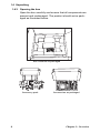
1.4.3 Opening the box
Open the box carefully and ensure that all components are
present and undamaged. The product should arrive packaged as illustrated below.
Box contents as packaged
http://www.ty
an.com
http://w
Accessory pack
8
ww.tyan
.com
Accessories as packaged
Chapter 1: Overview
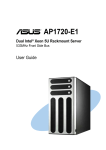
1.5 About the product
1.5
About the product
1.5.1 System front view and front panel
B2735G21S2
Power switch
LAN activity
indicator
Power indicator
IDE channel
status
USB ports
1
2
3
RST
Reset switch
1
disc
2
3
RST
B2735G21S4H
LAN activity
indicator
Power switch
Power indicator
HDD status
indicator
USB ports
1
2
3
1
2
3
4
RST
Reset switch
1
Chapter 1: Overview
2
3
1
2
3
4
RST
9
1.5 About the product
B2735G21U4H
Power switch
LAN activity
indicator
Power indicator
HDD activity indicator
USB ports
1
2
3
1
2
3
4
RST
Reset switch
1
2
RST
1.5.2 System rear view
Ventilation fan
EPS 12V 400W PSU
Power switch
Stacked PS/2 mouse and keyboard ports
RJ-45 LAN port
USB ports
VGA port
Serial port (COM 1)
RJ-45 LAN ports
Expansion slot
Note: All models have identical rear panel
features.
10
Chapter 1: Overview
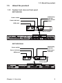
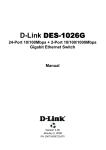
1.5 About the product
1.5.3 System internal views
B2735G21S2
1
2
3
13
4
12
5
6
11
10
7
9
8
1
LED control board
8
Riser card
2
Floppy disk drive (optional)
9
Power connector
3
Slim CD-ROM drive
10
Memory slots
4
Fan bracket
11
EPS 12V 400W power supply
5
S-ATA connector
12
Processor sockets
6
IDE connector
13
Front panel cable
7
FDD connector
Chapter 1: Overview
11
1.5 About the product
B2735G21S4H
1
3
2
14
13
4
12
5
6
11
7
10
9
8
1
Floppy disk drive
8
Riser card
2
LED control board
9
Power connector
3
Slim CD-ROM drive
10
Memory slots
4
Fan bracket
11
EPS 12V 400W power supply
5
S-ATA connector
12
Processor sockets
6
IDE connector
13
Front panel cable
7
FDD connector
14
4-port S-ATA backplane
12
Chapter 1: Overview
1.5 About the product
B2735G21U4H
1
3
2
14
13
4
12
5
6
11
10
7
9
8
1
Floppy disk drive
8
Riser card
2
LED control board
9
Power connector
3
Slim CD-ROM drive
10
Memory slots
4
Fan bracket
11
EPS 12V 400W power supply
5
S-ATA connector
12
Processor sockets
6
IDE connector
13
Front panel cable
7
FDD connector
14
4-port ultra320 SCSI backplane
Chapter 1: Overview
13
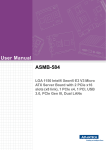
1.5 About the product
Block diagram
Intel Xeon
Intel Xeon
VRM
HOST BUS 400 or 533
DDR A DIMMS
SLOT# 2
SLOT#1
DD R
DD R
DD R
SO DIMM
DD R
BUS #02
HI 2.0
BUS #04
133MHz OR
100MHz PCI-X
DD R
MEM CNTRL AND DATA
BUS A
DD R
BUS #03
133MHz OR
100MHz PCI-X
Intel E7501 MCH
P64H2
ICH3_PIRQ#A
MEM CNTRL AND DATA
BUS B
SLOT# 1
*Option
DDR B DIMMS
GBIT
LAN
82546
HI 1.5
BUS # 00
SLOT# 4
SLOT# 3
BUS # 01
PCI 32/33MHz
PRIMARY
IDE CONN
RJ45
RJ45
SECONDARY
IDE CONN
Intel
82801ER
ICH5R
ATI
Rage XL
SATA
CONN
10/100
LAN
82551
8MB DISPLAY
MEMORY
USB
CONN
CRT
CONN
Winbond
83782D or
ADM1027
LPC BUS
BIOS
8Mb
RJ45
SERVER
MGMT
CONN
FIRMWARE HUB
SUPER-I/O
W83627HF
PRINTER
PORT
14
SERIAL
PORT
SERIAL
PORT
KBD
PORT
FLOPPY
CONN
Chapter 1: Overview
2.1 Before you begin
Chapter 2: Setting up
2.1
Before you begin
This chapter explains how to install motherboard components
including CPUs, memory modules, and PCI card. There are
also instructions in this section for installing S-ATA, SCSI and
IDE hard drives.
Careful attention should be given to the precautions mentioned in this section when setting up your system.
2.1.1 Work area
Make sure you have a stable, clean working environment.
Dust and dirt can get into components and cause malfunctions. Use containers to keep small components separated.
Putting all small components in separate containers prevents
them from becoming lost. Adequate lighting and proper tools
can prevent you from accidentally damaging the internal
components.
2.1.2 Tools
The following tools will be required to complete the installations described in this chapter.
•
•
A cross head (Phillips) screwdriver
A grounding strap and/or anti static pad
Most of the electrical and mechanical connectors in your system can be disconnected using your fingers. It is recommended that you do not use needle-nosed pliers to remove
connectors as these can damage the soft metal or plastic
parts of the connectors.
Chapter 2: Setting up
15
2.1 Before you begin
2.1.3 Precautions
Components and electronic circuit boards can be damaged
by static electricity. Working on a system that is connected to
a power supply can be extremely dangerous. Follow the
guidelines below to avoid damage to the Transport GX21 or
injury to yourself.
•
Ground yourself properly before removing the top
cover of the system. Unplug the power from the
power supply and then touch a safely grounded
object to release static charge (i.e. power supply
case). If available, wear a grounded wrist strap. Alternatively, discharge any static electricity by touching
the bare metal chassis of the unit case, or the bare
metal body of any other grounded appliance.
•
Avoid touching motherboard components, IC chips,
connectors, memory modules, and leads.
•
The motherboard is pre-installed in the system.
When removing the motherboard, always place it on
a grounded anti-static surface until you are ready to
reinstall it.
•
Hold electronic circuit boards by the edges only. Do
not touch the components on the board unless it is
necessary to do so. Do not flex or stress circuit
boards.
•
Leave all components inside the static-proof packaging that they ship with until they are ready for installation.
•
After replacing optional devices, make sure all
screws, springs, or other small parts are in place and
are not left loose inside the case. Metallic parts or
metal flakes can cause electrical shorts.
•
Always use the correct size screws and fixings when
installing or replacing components.
Note: All connectors are designed to fit
one way only, no force should required to
make a connection.
16
Chapter 2: Setting up
2.2 Installing motherboard components
2.2
Installing motherboard components
This section describes how to install CPUs, memory modules
and PCI card.
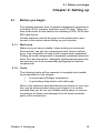
2.2.1 Removing the chassis cover
Follow these instructions to remove the Transport GX21
(B2735) chassis cover. This step is required before any other
procedures in this chapter can be undertaken.
1. Remove the six screws that secure the chassis cover.
2. Slide the cover in the direction of the arrow (A) and then
lift the cover off (B).
A
Chapter 2: Setting up
B
17
2.2 Installing motherboard components
2.2.2 Installing CPUs
This section describes how to install Intel® Xeon processors
and heatsinks in your Transport GX21 (B2735) system. This
section applies to all models.
1. Remove the chassis cover as described in section 2.2.1
Removing the chassis cover.
2. Locate the CPU sockets on the motherboard as shown
below.
3. Lift the CPU locking lever as shown below.
18
Chapter 2: Setting up
2.2 Installing motherboard components
4. Place the CPU in the CPU socket, ensuring that pin 1 is
located as shown in the following illustration.
pin 1
5. Press the CPU locking lever back down to secure the
CPU in the socket.
6. Repeat steps three to five for the second CPU.
7. Apply thermal grease to the top of the CPUs and place
the CPU heatsinks on the CPUs.
8. Tighten the four screws to secure the heatsinks in place
as shown below.
Note: CPU heatsinks must be removed to
install or remove memory modules.
Chapter 2: Setting up
19
2.2 Installing motherboard components
2.2.3 Installing memory
Follow the instructions in this section to install memory modules in your Transport GX21 (B2735) system.
1. Remove the chassis cover as described n section 2.2.1
Removing the chassis cover.
2. Locate the memory slots on the motherboard.
3. Press the memory slot locking levers in the direction of
the arrows as shown below.
Note: It is not possible to move the memory slot locking levers without first removing
the CPU heatsinks.
4. Align the memory module with the slot. The module will fit
only one way in the slot. Ensure that indentations in the
memory module line up with corresponding notches in
the memory slot.
20
Chapter 2: Setting up
2.2 Installing motherboard components
5. Insert the memory module into the slot as shown.
6. Ensure that the locking levers are firmly in place and that
the memory module is properly seated in the slot.
2.2.4 Installing a PCI card
Follow the instructions in this section to install a PCI card in
your Transport GX21 (B2735) system.
1. Remove the chassis cover as described in section 2.2.1
Removing the chassis cover.
2. Remove the PCI retention bar.
Chapter 2: Setting up
21
2.2 Installing motherboard components
3. Remove the screw securing the PCI faceplate to the
chassis.
4. Slide the PCI card clamp out as shown.
5. Slide the dust cover out.
22
Chapter 2: Setting up
2.2 Installing motherboard components
6. Press the PCI card into place in the slot on the riser card.
Ensure that the card is seated properly in the slot on the
riser card and that the riser card is properly seated in its
slot on the motherboard.
Insert PCI card tip
in slot here
Riser card
7. Reinsert the PCI card clamp.
Chapter 2: Setting up
23
2.2 Installing motherboard components
8. Insert the screw to secure the PCI card to the chassis.
24
Chapter 2: Setting up
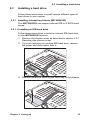
2.3 Installing a hard drive
2.3
Installing a hard drive
Follow these instructions to install various different types of
hard drives in your system.
2.3.1 Installing internal hard drives (B2735G21S2)
This B2735G21S2 can support internal IDE or S-SATA hard
drives.
2.3.1.1 Installing an IDE hard drive
Follow these instructions to instal an internal IDE hard drive
in your B2735G21S2 system.
1. Remove the chassis cover as described in section 2.2.1
Removing the chassis cover.
2. If you are replacing an existing IDE hard drive, remove
the power and data cables from it.
3. Remove the screw securing the HDD tray to the chassis.
Chapter 2: Setting up
25
2.3 Installing a hard drive
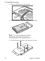
4. Slide the HDD tray out of the chassis.
5. Place a new HDD in the tray and slide it to the front.
Note: If an you are replacing an existing
hard disk you will need to remove the 4
screws securing it to the tray and remove it.
6. Secure the new disk drive in the tray with 4 screws.
26
Chapter 2: Setting up
2.3 Installing a hard drive
7. Reinsert the HDD tray and secure it to the chassis with a
screw.
8. Connect the IDE data cable and power cable to the HDD.
2.3.1.2 Installing an internal S-ATA hard drive
Follow these instructions to install an internal S-ATA hard
drive in your B2735G21S2 system.
1. Remove the chassis cover as described in section 2.2.1
Removing the chassis cover.
2. If you are replacing an existing S-ATA hard drive, remove
the power and data cables from it.
Chapter 2: Setting up
27
2.3 Installing a hard drive
3. Remove the screw securing the HDD tray to the chassis.
4. Slide the HDD tray out of the chassis.
5. Place a new HDD in the tray and slide it to the front.
Note: If an you are replacing an existing
hard disk you will need to remove the 4
screws securing it to the tray and remove it.
28
Chapter 2: Setting up
2.3 Installing a hard drive
6. Secure the new disk drive in the tray with 4 screws.
7. Reinsert the HDD tray and secure it to the chassis with a
screw.
8. Connect the S-ATA data cable and power cable to the
HDD.
Chapter 2: Setting up
29
2.3 Installing a hard drive
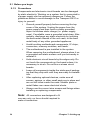
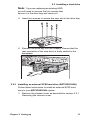
2.3.2 Installing an external S-ATA hard drive (B2735G21S4H)
Follow these instructions to install an external S-ATA hard
drive in your B2735G21S4H system.
1. Remove the chassis cover as described in section 2.2.1
Removing the chassis cover.
2. Press the drive bay locking latch in the direction of the
arrow (1) and pull the locking lever open (2).
1
2
3
1
2
RST
1
2
3. Slide the drive bay out.
1
2
3
1
2
RST
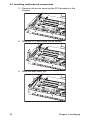
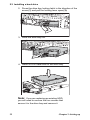
4. Place a S-ATA drive in the drive bay.
30
Chapter 2: Setting up
2.3 Installing a hard drive
Note: If you are replacing an existing HDD,
you will need to remove the four screws that
secure it in the drive bay and remove it.
5. Insert four screws to secure the new unit in the drive bay.
6. Reinsert the drive bay into the chassis. Ensure that the
rear connector of the new drive is firmly seated in the
backplane.
1
2
3
1
2
RST
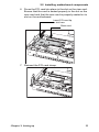
2.3.3 Installing an external SCSI hard drive (B2735G21U4H)
Follow these instructions to install an external SCSI hard
drive in your B2735G21U4H system.
1. Remove the chassis cover as described in section 2.2.1
Removing the chassis cover.
Chapter 2: Setting up
31
2.3 Installing a hard drive
2. Press the drive bay locking latch in the direction of the
arrow (1) and pull the locking lever open (2).
1
2
3
1
2
RST
1
2
3. Slide the drive bay out.
1
2
3
1
2
RST
4. Insert a SCSI hard drive in the drive bay.
Note: If you are replacing an existing HDD,
you will need to remove the four screws that
secure it in the drive bay and remove it.
32
Chapter 2: Setting up
2.3 Installing a hard drive
5. Insert four screws to secure the new unit in the drive bay.
6. Reinsert the drive bay into the chassis. Ensure that the
rear connector of the new drive is firmly seated in the
backplane.
1
2
3
1
Chapter 2: Setting up
2
RST
33
2.4 Rack mounting
2.4
Rack mounting
Follow these instructions to mount the Transport GX21
(B2735) into an industry standard 19" rack.
Note: Before mounting the
Transport GX21 in a rack, ensure that all
internal components have been installed and
that the unit has been fully tested. Maintenance can be performed on the unit while in
a rack but it is preferable to install the device
in a fully operational condition.
1. Screw the mounting ears to the Transport GX21 as
shown using 4 screws from the supplied nuts, screws
and washers kit.
2. Screw the sliding rail mounting brackets to the sliding
rails as shown, using the short black screws from the
supplied nuts, screws and washers kit.
Note: Ensure that the brackets with the cut
away section (to accommodate the handles
34
Chapter 2: Setting up
2.4 Rack mounting
on the front of the unit) are fixed to the front
end of the rail.
3. Fully extend the sliding rails until they lock.
Note: Do not tighten the brackets to the
rails as you will need to adjust their position
later.
4. Screw each sliding rail to the side of the Transport GX21
as shown. You will need 3 short, silver colored screws
from the supplied nuts, screws and washers kit, for each
rail.
5. Return the sliding rails to their shortest position.
Note: When fully extended, the sliding rails
will lock. The release mechanism is located
on the sliding rail as shown. Press the
Chapter 2: Setting up
35
2.4 Rack mounting
release mechanism while pushing the sliding
rails to shorten them.
6. With the rails in their shortest position, adjust both front
mounting brackets so that they are flush with the front of
the unit.
7. Accurately measure the depth of your rack and adjust the
rear brackets accordingly.
8. When all brackets are positioned correctly, tighten them.
36
Chapter 2: Setting up
2.4 Rack mounting
9. Lift the unit into place in the rack and screw it into place
as shown.
1
2
3
1
2
RST
Note: To avoid injury, it is strongly recommended that two people lift the
Transport GX21 into place while a third person screw it to the rack.
Chapter 2: Setting up
37
2.4 Rack mounting
38
Chapter 2: Setting up
3.1 Introduction
Chapter 3: Replacing pre-installed
components
3.1
Introduction
This chapter describes how to replace all the pre-installed
components of your Transport GX21 (B2735), including CPU,
PCI card, riser card, memory modules, motherboard, CDROM drive, floppy disk drive and LED control board. There is
also a section covering the replacement of the 4 port S-ATA
backplane (B2735G21S4H only), and a section covering the
replacement of the 4 port SCSI back plane (B2735G21U4H
only).
Before you attempt to replace any components, make sure
you have read section 2.1 Before you begin, in chapter 2,
which describes the precautions you need to take and the
tools you will require.
3.2
Replacing motherboard components
Follow these instructions to remove motherboard components and replace the motherboard.
3.2.1 Disconnecting all motherboard cables
When replacing the motherboard or certain motherboard
components, it my be necessary to remove cables connected
to the motherboard. Follow these instructions to remove all
motherboard cabling. See section Technical support in the
Appendix for detailed diagrams of cable locations.
Chapter 3: Replacing pre-installed components
39
3.2 Replacing motherboard components
1. Disconnect ATX power cables.
Main power
EPS 12V power
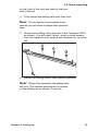
2. Disconnect CD-ROM drive cable (A) (all models) and
S-ATA hard drive cable (B) (B2735G21S2 only).
A
B
40
Chapter 3: Replacing pre-installed components
3.2 Replacing motherboard components
Note: If there is FDD or IDE HDD installed
in the bay beneath the CD-ROM drive, you
will have to disconnect those cables too
before you can remove the motherboard.
3. Disconnect front panel LED and USB connectors.
Front panel LED connector
USB connector
Chapter 3: Replacing pre-installed components
41
3.2 Replacing motherboard components
3.2.2 Replacing the motherboard
Follow these instructions to remove the motherboard from
your Transport GX21 (B2735).
Note: Before removing the motherboard
you must remove all cable connections to the
motherboard. See section 3.2.1 Disconnecting all motherboard cables for details on how
to do this.
1. Remove the fan assembly bracket from the chassis.
2. Remove the PCI retention bar.
42
Chapter 3: Replacing pre-installed components
3.3 Replacing the CD-ROM drive
3. Remove the nine screws that secure the motherboard to
the chassis.
4. Remove the motherboard from the chassis.
3.3
Replacing the CD-ROM drive
This section describes how to remove and replace the CDROM drive in your Transport GX21 (B2735) system.
3.3.1 Replacing the slim CD-ROM drive (B2735G21S2)
Follow these instructions to replace the slim CD-ROM drive in
your B2735G21S2 system.
1. Remove the chassis cover as described in section 2.2.1
Removing the chassis cover.
2. Locate the drive bay housing the FDD and slim CD-ROM
drive and remove power and data cables from both.
Chapter 3: Replacing pre-installed components
43
3.3 Replacing the CD-ROM drive
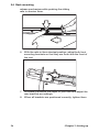
3. Remove the two screws that secure the CD-ROM backplane to the CD-ROM drive.
4. Remove the four screws that secure the drive bay to the
chassis and lift the drive bay free.
5. Slide the slim CD-ROM from the drive bay.
44
Chapter 3: Replacing pre-installed components
3.3 Replacing the CD-ROM drive
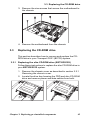
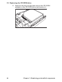
3.3.2 Replacing the CD-ROM drive
(B2735G21U4H/B2735G21S4H)
Follow these instructions to replace the slim CD-ROM drive in
your B2735G21U4H or B2735G21S4H system.
1. Remove the chassis cover as described in section 2.2.1
Removing the chassis cover.
2. Remove the power and data cables from the CD-ROM
drive.
3. Remove the two screws that secure the CD-ROM bracket
to the chassis and lift it free.
4. Lift the CD-ROM drive from the chassis.
Chapter 3: Replacing pre-installed components
45
3.3 Replacing the CD-ROM drive
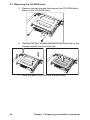
5. Remove the two screws that secure the CD-ROM
adapter to the CD-ROM drive and remove it.
46
Chapter 3: Replacing pre-installed components
3.4 Replacing the floppy disk drive
3.4
Replacing the floppy disk drive
This chapter describes how to replace the floppy disk drive.
3.4.1 Replacing the floppy disk drive (B2735G21S2)
Follow these instructions to replace the FDD in your
B2735G21S2 system.
1. Remove the chassis cover as described in section 2.2.1
Removing the chassis cover.
2. Locate the drive bay housing the slim CD-ROM drive and
the FDD and remove power and data cables from both.
Note: Unless you are intending to replace
the CD-ROM drive, there is no need to
remove the CD-ROM backplane.
3. Remove the 4 screws that secure the drive bay to the
chassis and lift the drive bay free.
4. Remove the four screws that secure the FDD in the drive
bay and slide the unit out of the drive bay.
Note: The FDD bay can be used to house
an additional IDE HDD if required.
Chapter 3: Replacing pre-installed components
47
3.4 Replacing the floppy disk drive
3.4.2 Replacing the floppy disk drive
(B2735G21S4H/B2735G21U4H).
Follow these instructions to replace the slim floppy disk drive
in your B2735G21U4H or B2735G21S4H system.
1. Remove the chassis cover as described in section 2.2.1
Removing the chassis cover
2. Remove the ribbon cable from the back of the slim floppy
disk drive.
Note: The slim floppy disk drive uses a single ribbon cable that provides it with both
power and data. To remove the ribbon cable
you must operate the release mechanism as
shown below.
3. Remove the two screws that secure the floppy disk
bracket to the chassis and lift it free.
48
Chapter 3: Replacing pre-installed components
3.5 Replacing the LED control board
4. Remove the floppy disk drive from the chassis.
3.5
Replacing the LED control board
Follow these instructions to replace the LED control board.
1. Remove the two screws that secure the metal retaining
plate to the chassis and lift it free.
Chapter 3: Replacing pre-installed components
49
3.6 Replacing the storage backplane
2. Remove the front panel ribbon cable from the rear of the
LED control panel.
3. Remove the two screws that secure the LED control
panel to the chassis and lift the board free of the chassis.
3.6
Replacing the storage backplane
This section describes how to replace the S-ATA or SCSI
backplane on your Transport GX21 (B2735).
3.6.1 S-ATA backplane (B2735G21S4H)
3.6.1.1 Replacing the S-ATA backplane (B2735G21S4H)
Follow these instructions to replace the S_ATA backplane on
your B2735G21S4H system.
50
Chapter 3: Replacing pre-installed components
3.6 Replacing the storage backplane
1. Remove the chassis cover as described in section 2.2.1
Removing the chassis cover.
2. Remove the two screws that secure the metal retaining
plate to the chassis and lift it free as shown.
3. Remove all cables connected to the S-ATA backplane,
including front panel cable, power cables, and S-ATA
data cables.
4. Remove the six screws that secure the S-ATA backplane
bracket to the chassis.
5. Remove the S-ATA backplane bracket and backplanes
free from the chassis.
Chapter 3: Replacing pre-installed components
51
3.6 Replacing the storage backplane
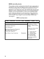
3.6.1.2 S-ATA backplane features
J6 1 square C
connector
Fan 5 connector
J3 serial ATA 7 pin
connector
Fan 4 connector
Fan 3 connector
J4 HDD2 serial ATA
7 pin connector
Fan 2 connector
BZ1 buzzer
6
5
4
3
2
1
ON
S1 Function set
switch
KE
Fan 1 connector
P1 LED pin output, 2 x 6 pin
header
J5 DC power input connector
Note: B2735G21S4H is shipped with two
2-port S-ATA backplanes to support 4 hotswap S-ATA hard disk drives
52
Chapter 3: Replacing pre-installed components
3.6 Replacing the storage backplane
3.6.2 SCSI backplane (B2735G21U4H)
3.6.2.1 Replacing the SCSI backplane (B2735G21U4H)
Follow these instructions to replace the SCSI backplane on
your B2735G21U4H system.
1. Remove the chassis cover as described in section 2.2.1
Removing the chassis cover.
2. Remove the two screws that secure the metal retaining
plate to the chassis and lift it free as shown.
3. Remove all cables connected to the SCSI backplane,
including power cables, SCSI cable, and floppy disk drive
cable.
Note: The slim floppy disk drive uses a single ribbon cable that provides it with both
power and data. To remove the ribbon cable
you must operate the release mechanism as
shown below.
Chapter 3: Replacing pre-installed components
53
3.6 Replacing the storage backplane
4. Remove the 10 screws that secure the SCSI backplane
to the chassis and lift the backplane free.
54
Chapter 3: Replacing pre-installed components
3.6 Replacing the storage backplane
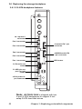
3.6.2.2 SCSI backplane features
J8 big 4P 90
deg
J5 80 pin SCA2
J7 big 4P 90
deg
F3 fan 3P
J4 80 pin SCA2
U14 MPU
F1/2 fan 3P
J6 front panel
display board
J3 80 pin SCA2
J11 floppy 34P
JP2 to system
JP1 to 12C
J1 SCSI 68 pin
Chapter 3: Replacing pre-installed components
J2 80 pin SCA2
55
3.7 Replacing the power supply
3.7
Replacing the power supply
Follow these instructions to replace the power supply in your
Transport GX21 (B2735) system.
1. Remove the chassis cover as described in section 2.2.1
Removing the chassis cover.
2. Remove the four screws that secure the fan assembly to
the chassis and lift it free.
3. Disconnect power cables from the motherboard, HDDs,
FDDs, CD-ROM drive and fans. See section 3.4.2 Disconnecting Cables for details on how to do this.
4. Remove the four screws that secure the power supply to
the chassis and lift the unit free.
56
Chapter 3: Replacing pre-installed components
3.8 Replacing the cooling fans
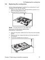
3.8
Replacing the cooling fans
Follow these instructions to replace the cooling fans in your
Transport GX21 (B2735) system.
1. Remove the chassis cover as described in section 2.2.1
Removing the chassis cover.
2. Remove the PCI retention bar
Note: You may need to cut the cable ties
that secure the fan power cables before
attempting to unplug them.
3. Remove the power cables for the 5 fans from the motherboard.
4. Remove the four screws that secure the fan bracket to
the chassis.
5. Lift the fan bracket free of the unit
Chapter 3: Replacing pre-installed components
57
3.8 Replacing the cooling fans
6. Remove the four screws securing each fan to the fan
bracket to remove them from the fan bracket.
Note: The Transport GX21 (B2735) uses
two different types of cooling fans which
operate at different speeds. The two fans
installed nearest the power supply have a
peak speed of 15,000 rpm. The remaining 3
fans have a peak speed of 11,500 rpm. The
two fans nearest the power supply should be
connected to the speed-controllable pin
headers (CPU1_FAN and CPU2_FAN) on
the mother board. See 3.8.1 Cooling fan connections.
58
Chapter 3: Replacing pre-installed components
3.8 Replacing the cooling fans
3.8.1 Cooling fan connections
The 2 fans closest to the power supply
should be connected to the CPU_1FAN
and CPU_2FAN pin headers on the motherboard.
CPU1_FAN pin
header
Chapter 3: Replacing pre-installed components
CPU2_FAN pin
header
59
3.8 Replacing the cooling fans
60
Chapter 3: Replacing pre-installed components
Appendix
BIOS
Introduction
Your Transport GX21 (B2735) system includes a powerful
Tiger i7501R S2735 motherboard with AMI BIOS v8.0 on 4
MB flash ROM.
The BIOS is the motherboard’s basic input/output system.
The BIOS contains all the settings required to control the keyboard, display, disk drives, serial communications, and a
number of miscellaneous functions. This section of the
appendix describes the various BIOS settings that can be
used to configure your system.
BIOS setup utility
With the BIOS setup utility, you can modify BIOS settings and
control the features of your system. The setup utility uses a
number of menus.
Note: All menus shown in this section are
based on a typical system. The actual menus
displayed on your screen may look different
depending on the hardware and features
installed.
To start the BIOS setup utility:
1. Turn on or reboot your system.
2. Press <Del> during POST (F4 on remote console) to
start the BIOS setup utility
61
BIOS setup utility
Main
Advanced
PCI/PnP
Boot
Security
Chipset
Exit
System Overview
Use [Enter], [TAB] or
[SHIFT_TAB] to select
a field
AMIBIOS
Version
:08.00.09
Build Date :xx/xx/2003
ID
:0ABBP006
Processor
Type
:Intel® Xeon™ CPU x.xx GHz
Logical Count : x
System Memory
Size
: xxxx MB
System Time
System Date
[12:59:59]
[xxx xx/xx/2003
Use [+] or [-] to configure system time.
Select Screen
Select item
+/- Change option
Tab Select field
F1 General Help
F10 Save and Exit
ESC Exit
To select an item:
Use the <Arrow> keys to make a selection.
To display a submenu (a pointer
marks all submenus)
Use the arrow keys to move the cursor to the required submenu and press <Enter>.
62
BIOS menu bar
The menu bar at the top of the window lists the following
selections:
Menu bar selections
Main
To configure basic system setups
Advanced
Configure advanced chipset options
PCI/PnP
Configure legacy PnP or PCI settings
Boot
Configure system boot order
Security
Configure user and supervisor passwords
Chipset
Configure chipset management features
Exit
Exit setup utility
Note: Options written in bold type represent the BIOS setup default.
63
BIOS legend bar
The following chart describes the legend keys and their functions.
BIOS legend bar
Key
Function
<F1> or <Alt-H>
General help window
<ESC>
Exit current window
arrow keys
arrow keys
Select a different window
Move cursor up/down
<Tab> or <Shift-Tab>
Cycle cursor up/down
<Home> or <End>
Move cursor to the top or bottom of the window
<PgUp> or <PgDn>
Move cursor tot he next or previous page
<F5> or <->
Select the previous value/setting of the field
<F6>, <+> or <Space>
Select the next value/setting of the field
<F8>
Load fail safe default configuration values
<F9>
Load optimal default configuration values
<F10>
Save and exit
<Enter>
Execute command or select submenu
64
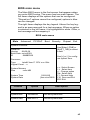
BIOS main menu
The Main BIOS menu is the first screen that appears when
you enter BIOS setup. The menu has two main frames. The
left frame displays all the options that can be configured.
"Grayed-out" options cannot be configured, options in blue
can be changed.
The right frame displays the key legend. Above the key legend is an area reserved for a text message. When an option
is selected in the left frame, it is highlighted in white. Often, a
text message will accompany it.
BIOS main menu
Main
Advanced
PCI/PnP
Boot
Security
Chipset
Exit
System Overview
Use [Enter], [TAB] or
[SHIFT_TAB] to select
a field
AMIBIOS
Version
:08.00.09
Build Date :xx/xx/2003
ID
:0ABBP006
Processor
Type
:Intel® Xeon™ CPU x.xx GHz
Logical Count : x
System Memory
Size
: xxxx MB
System Time
System Date
Feature
[12:59:59]
[xxx xx/xx/2003
Option
Use [+] or [-] to configure system time.
Select Screen
Select item
+/- Change option
Tab Select field
F1 General Help
F10 Save and Exit
ESC Exit
Description
Main
System time
HH:MM:SS
Set the system time
System date
MM:DD:YY
Set the system date
65
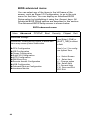
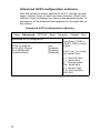
BIOS advanced menu
You can select any of the items in the left frame of the
screen, such as Super I/O Configuration, to go to the sub
menu for that item. You can display an Advanced BIOS
Setup option by highlighting it using the <Arrow> keys. All
Advanced BIOS Setup options are described in this section.
The Advanced BIOS Setup screen is shown below.
BIOS advanced menu
Main
Advanced
PCI/PnP
Boot
Security
Chipset
Exit
Advanced Settings
WARNING: Setting wrong values in below sections may cause system malfunction.
CPU Configuration
IDE Configuration
Floppy Configuration
Super I/O Configuration
ACPI Configuration
DMI Event Log
Remote Access Configuration
USB Configuration
Onboard Devices Configuration
Hardware Monitor
66
Use [Enter], [TAB] or
[SHIFT_TAB] to select
a field
Use [+] or [-] to configure system time.
Select Screen
Select item
+/- Change option
Tab Select field
F1 General Help
F10 Save and Exit
ESC Exit
BIOS advanced menu
Features
Option
Description
Advanced settings
CPU Configuration
Menu Item
Configure CPU
IDE Configuration
Menu Item
Configure the IDE devices(s)
Floppy Configuration
Menu Item
Configures devices connected to
the floppy controller
Super I/O Configuration
Menu Item
Configures devices connected to
the SUper I/O controller
ACPI Configuration
Menu Item
Section for advanced ACPI configuration
DMI Event Logging
Menu Item
Views and controls event log
Remote Access Configuration
Menu Item
Configures Console Redirect
USB Configuration
Menu Item
Configures USB controller and
legacy device support
Onboard devices Configuration
Menu Item
Use this section to Enable/Disable special onboard devices
Hardware monitor
Menu Item
Hardware Monitor and Display
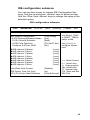
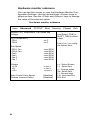
CPU configuration submenu
You can use this screen to change the CPU Settings. Use the
up and down <Arrow> keys to select an item. Use the <Plus>
and <Minus> keys to change the value of the selected option.
67
CPU configuration submenu
Main
Advanced
PCI/PnP
Boot
Security
Chipset
Exit
CPU Configuration submenu
Manufacturer: Intel
Brand String : Intel® Xeon™ CPU x.xx GHz
Use [Enter], [TAB] or
[SHIFT_TAB] to select
a field
Cache L2
Cache L3
Use [+] or [-] to configure system time.
: 512 KB
: 0
KB
Ratio Status : Unlocked
Ratio Actual Value : 15
Ratio CMOS Setting
Hyper Threading
[255]
[Embedded]
Feature
Option
Select Screen
Select item
+/- Change option
Tab Select field
F1 General Help
F10 Save and Exit
ESC Exit
Description
Configure advanced CPU settings
Ratio Status
Unlocked
Ratio Actual
value
xx
Ratio CMOS
Setting
255
Sets the ratio between CPU Core
Clock and the FSB frequency.
Note: If an invalid ratio is set in
CMOS, actual and set point values
may differ
Hyper Threading
Enabled
Disabled
ENABLE: Enable CPU HyperThreading for HT enabled processor(s).
DISABL:E: Disable CPU HyperThreading for HT enabled processor(s).
68
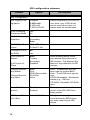
IDE configuration submenu
You can use this screen to change IDE Configuration Settings. Use the up and down <Arrow> keys to select an item.
Use the <Plus> and <Minus> keys to change the value of the
selected option.
IDE configuration submenu
Main
Advanced
PCI/PnP
Boot
Security
Chipset
Exit
IDE Configuration
IDE Legacy Configuration
S-ATA Running Enhanced Mode
P-ATA Channel Selection
S-ATA Ports Definition
Configure S-ATA as RAID
IDE channel 0 Master
IDE channel 0 Slave
IDE channel 1 Master
IDE channel 1 Slave
IDE channel 2 Master
IDE channel 2 Slave
IDE channel 3 Master
IDE channel 3 Slave
Hard Disk Write Protect
IDE Detect Time Out (Sec)
ATA (PI) 80 pin Cable Detection
[P-ATA Only]
[Yes]
[Both]
[P0-3rd/P1-4th]
[No]
: [xxxx]
: [xxxx]
: [xxxx]
: [xxxx]
: [xxxx]
: [xxxx]
: [xxxx]
: [xxxx]
[Disable]
[xx]
[Host & Device]
Use [Enter], [TAB]
or [SHIFT_TAB] to
select a field
Use [+] or [-] to
configure system
time.
Select Screen
Select item
+/- Change option
Tab Select field
F1 General Help
F10 Save and Exit
ESC Exit
69
IDE configuration submenu
Feature
Option
Description
IDE Configuration
IDE Legacy Configuration
Disabled
P-ATA only
S-ATA only
P-ATA & S-ATA
S-ATA Running
Enhanced Mode
Yes
No
P-ATA Channel
Selection
Primary
Secondary
Both
S-ATA Ports Definition
P0-3rd/P1-4th
P0-4th/P1-3rd
Configure S-ATA
as RAID
No
Yes
S-ATA port 0/1
Master
Both
Primary
Secondary
Disabled
While entering setup, BIOS
auto detects the presence of
IDE devices. This displays the
status of auto detection of IDE
devices.
Primary/Secondary Slave
Auto
User
ATAPI Removable
CD-ROM
None
Auto - To determine the IDE
drive type by system BIOS
User - To set IDE drive type by
user
ATAPI Removable - Read/write
media (e.g... IDE zip)
CD-ROM - Readable CD-ROM
drive
Hard Disk Write
protect
Disabled
Enabled
This option protects the first
sector of the IDE HDD from
being written
IDE Detect Time
Out (Sec)
0, 5, 10,15,..35
Configure the time (in seconds) before the BIOS times
out when detecting an IDE
device
S-ATA port 0/1
Slave
Primary/Secondary Master
70
Select combination you wish to
use. Note, only 4 IDE drives
can be used at one time, no
matter what the combination.
Feature
ATA (PI) 80 pin
Cable Detection
Option
Description
Host and Device
Host
Device
Toggles the detection of 80
wire IDE cables
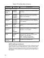
S-ATA Port/Primary IDE/Secondary IDE configuration submenu
You can use this screen to change SATA Port / Primary IDE /
Secondary IDE Configuration Settings. Use the up and down
<Arrow> keys to select an item. Use the <Plus> and <Minus>
keys to change the value of the selected option.
S-ATA Port/Primary IDE/Secondary IDE Configuration submenu
Main
Advanced
PCI/PnP
Boot
Security
Chipset
Exit
S-ATA Port 0 IDE Master
Device:
[P-ATA Only]
Type
LBA/Large Mode
Block (Multi - Sector transfer)
PIO Mode
S.M.A.R.T
32 Bit Data Transfer
[Auto]
[Auto]
[Auto]
[Auto]
[Auto]
[Disabled]
Use [Enter], [TAB] or
[SHIFT_TAB] to
select a field
Use [+] or [-] to configure system time.
Select Screen
Select item
+/- Change option
Tab Select field
F1 General Help
F10 Save and Exit
ESC Exit
71
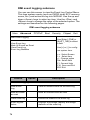
Floppy configuration submenu
You can use this screen to change the Floppy Configuration
Settings. Use the up and down <Arrow> keys to select an
item. Use the <Plus> and <Minus> keys to change the value
of the selected option.
Floppy configuration submenu
Main
Advanced
PCI/PnP
Boot
Security
Chipset
Exit
Floppy Configuration
Floppy A
Floppy B
[1.44 MB 3 1/2”]
[Disabled]
Use [Enter], [TAB] or
[SHIFT_TAB] to select
a field
Use [+] or [-] to configure system time.
Select Screen
Select item
+/- Change option
Tab Select field
F1 General Help
F10 Save and Exit
ESC Exit
72
Floppy configuration submenu
Features
Option
Description
Floppy Configuration
Floppy A
Disabled
360 KB 5 1/4”
1.2 MB 5 1/4”
720 KB 3 1/2”
1.44 MB 3 1/2”
2.88 MB 3 1/2”
This setting defines the type of
floppy drive installed in the system
Floppy B
Disabled
360 KB 5 1/4”
1.2 MB 5 1/4”
720 KB 3 1/2”
1.44 MB 3 1/2”
2.88 MB 3 1/2”
This setting defines the type of
floppy drive installed in the system
Super I/O configuration submenu
You can use this screen to change the configuration of Super
I/O. Use the up and down <Arrow> keys to select an item.
Use the <Plus> and <Minus> keys to change the value of the
selected option.
Super I/O configuration submenu
Main
Advanced
PCI/PnP
Boot
Security
Win627 Super I/O chipset
Onboard Floppy Controller
Serial Port1 Address
Serial Port2 Address
Serial Port2 Mode
Parallel Port Address
Parallel Port Mode
Parallel Port IRQ
[Enabled]
[3F8/IRQ4]
{Disabled]
[Disabled]
[Disabled]
[Normal]
[IRQ7]
Chipset
Exit
Use [Enter], [TAB] or
[SHIFT_TAB] to select
a field
Use [+] or [-] to configure system time.
Select Screen
Select item
+/- Change option
Tab Select field
F1 General Help
F10 Save and Exit
ESC Exit
73
Super I/O configuration submenu
Feature
Option
Description
Win627 Super I/O Chipset
Onboard
floppy controller
Enabled
Disabled
Enables or disables the onboard floppy
controller
Serial Port 1
Address
3F8/IRQ4
3E8/IRQ4
2E8/IRQ3
Disabled
Sets the serial port 1 (com 1) base I/O
address and an interrupt number. Disabled - port disabled
Serial Port 2
Address
3F8/IRQ3
3E8/IRQ4
2E8/IRQ3
Disabled
Sets the serial port 2 (com 2) base I/O
address and interrupt number. Disabled port disabled
Serial Port 2
Mode
Normal
IrDA
ASK IR
Allows BIOS to Select Mode for serial
port 2
Parallel port
address
378
278
3BC
DIsabled
Assigns the Parallel Port I/O address.
Disabled - Port disabled
Parallel Port
Mode
Bi-Directional
Normal
EPP
ECP
Configures parallel port mode.
Bi-directional - send and receive data.
Normal - can send data.
EPP - Enhanced parallel port.
ECP - Extended capability port.
Parallel Port
Interrupt
IRQ7
IRQ5
Assigns IRQ to parallel port
ACPI settings submenu
Use this screen to change options for ACPI. Use the up and
down <Arrow> keys to select an item. Use the <Plus> and
<Minus> keys to change the value of the selected option. A
description of the selected item appears on the right side of
the screen.
74
ACPI settings submenu
Main
Advanced
PCI/PnP
Boot
Security
Chipset
Exit
ACPI Settings
[Yes]
Use [Enter], [TAB] or
[SHIFT_TAB] to select
a field
WOL S48S5 Support
[Enabled]
Use [+] or [-] to configure system time.
Power Button Instant Off
[Enabled]
After Power Failure
[Always Off]
ACPI Aware O/S
Advanced ACPI Configuration
Feature
Option
Select Screen
Select item
+/- Change option
Tab Select field
F1 General Help
F10 Save and Exit
ESC Exit
Description
ACPI Settings
ACPI Aware
O/S
Yes
No
Yes - Allows the system to utilize
ACPI (Advanced Configuration and
Power Interface) specification
WOL S4855
Support
Enabled
Disabled
Enable WOL event before system
goes to S4855 mode
The power
Enabled
Disabled
The Power Button Instant Off function only supports non ACPI O/S
After Power
Failure
Always On
Always Off
Previous State
Determines the mode of operation if
an AC power failure occurs
75
Advanced ACPI configuration submenu
Use this screen to select options for ACPI. Use the up and
down <Arrow> keys to select an item. Use the <Plus> and
<Minus> keys to change the value of the selected option. A
description of the selected item appears on the right side of
the screen.
Advanced ACPI configuration submenu
Main
Advanced
PCI/PnP
Boot
Security
Chipset
Exit
Advanced ACPI Configuration
ACPI 2.0 Support
ACPI APIC Support
Ami OEMB table
Headless Mode
[No]
[Enabled]
[Enabled]
[Disabled]
Use [Enter], [TAB] or
[SHIFT_TAB] to select
a field
Use [+] or [-] to configure system time.
Select Screen
Select item
+/- Change option
Tab Select field
F1 General Help
F10 Save and Exit
ESC Exit
76
Advanced ACPI configuration
Feature
Option
Description
Advanced ACPI Configuration
ACPI 2.0
Support
Yes
No
Set this value to allow or prevent the system
complying with the ACPI 2.0 specification
APIC Support
Enabled
Disabled
This option allows you to delete whether or not
to enable ACPI management features
Ami OEMB
Table
Enabled
Disabled
Set this value to allow the ACPI BIOS to add a
pointer to an OEMB table in the Root System
Description Table (RSDT). Note, OEMB table
is used to pass POST data to the AML code
during ACPI O/S operations
Headless
Mode
Enabled
Disabled
Enable/Disable Headless operation mode
through ACPI
77
DMI event logging submenu
You can use this screen to view the Event Log Control Menu.
This logs system events (such as CMOS clear, ECC memory
errors, etc.) and writes the log into NVRAM. Use the up and
down <Arrow> keys to select an item. Use the <Plus> and
<Minus> keys to change the value of the selected option. The
settings are described on the following pages.
DMI event logging submenu
Main
Advanced
PCI/PnP
Boot
Security
Chipset
Exit
DMI Event Logging
View Event Log
Mark All Events as Read
Clear Event Log
Event Log Statistics
Use [Enter], [TAB] or
[SHIFT_TAB] to select
a field
Use [+] or [-] to configure system time.
Select Screen
Select item
+/- Change option
Tab Select field
F1 General Help
F10 Save and Exit
ESC Exit
Feature
Option
Description
DMI Event Logging
View Event
Log
View all unread events on the event log
Mark all events
as read
mark all unread events as read
Clear event log
Discard all events in the event log
Event log statistics
Displays the storage capacity and usage
statistics of the event log
78
Remote access configuration submenu
You can use this screen to view the Remote Access Configuration Menu. This feature allows remote access to the Server
via serial port. Use the up and down <Arrow> keys to select
an item. Use the <Plus> and <Minus> keys to change the
value of the selected option.
Remote access configuration
Main
Advanced
PCI/PnP
Boot
Security
Chipset
Exit
Configure Remote Access Type and Parameters
Remote Access
Use [Enter], [TAB] or
[SHIFT_TAB] to select
a field
[Disabled]
Use [+] or [-] to configure system time.
Select Screen
Select item
+/- Change option
Tab Select field
F1 General Help
F10 Save and Exit
ESC Exit
Feature
Option
Description
Configure Remote Access Type and Parameters
Remote Access
Disabled
Serial
SMDC
Enables remote access to system
through the serial port
79
USB configuration menu
You can use this screen to view the USB Configuration
Menu. Use the up and down <Arrow> keys to select an item.
Use the <Plus> and <Minus> keys to change the value of the
selected option. The settings are described on the following
pages.
USB configuration menu
Main
Advanced
PCI/PnP
Boot
Security
Chipset
Exit
USB Configuration
Use [Enter], [TAB] or
[SHIFT_TAB] to select
a field
Model Version - X.XX.X-XX
USB Devices Enabled:
None
USB Function
Legacy USB Support
USB 2.0 Controller
USB 2.0 Controller Mode
[4 USB Ports]
[Enabled]
[Enabled]
[HiSpeed]
USB Mass Storage Device Configuration
80
Use [+] or [-] to configure system time.
Select Screen
Select item
+/- Change option
Tab Select field
F1 General Help
F10 Save and Exit
ESC Exit
USB configuration submenu
Feature
Option
Description
USB Configuration
USB Function
Disabled
2 USB ports
4 USB ports
Enables USB host controllers
Legacy USB
Support
Auto
Disabled
Enabled
Enables support for legacy USB devices
such as keyboards, mice and bootable
USB devices
USB 2.0 Controller
Disabled
Enabled
Select “Enabled” if your system contains
a USB controller and you have a USB
keyboard
USB 2.0 Controller Mode
FullSpeed
HiSpeed
Configures the USB 2.0 controller in HiSpeed (480 Mbps_ or FullSpeed 12 Mbps)
81
USB mass storage device configuration submenu
You can use this screen to view the USB Mass Storage
Device Configuration Menu. Use the up and down <Arrow>
keys to select an item. Use the <Plus> and <Minus> keys to
change the value of the selected option.
USB mass storage device configuration
Main
Advanced
PCI/PnP
Boot
Security
Chipset
Exit
USB Mass Storage Device Configuration
USB Mass Storage Reset Delay
[20 Sec]
No USB Mass Storage Device Detected
Use [Enter], [TAB]
or [SHIFT_TAB] to
select a field
Use [+] or [-] to
configure system
time.
Select Screen
Select item
+/- Change option
Tab Select field
F1 General Help
F10 Save and Exit
ESC Exit
Feature
Option
Description
USB Configuration
USB Mass Storage
Reset Delay
82
10 Sec
20 Sec
30 Sec
40 Sec
Number of seconds POST waits for
the USB storage device after start until
command
Onboard devices configuration submenu
Use this screen to changer the Onboard Devices Configuration Settings. Use the up and down <Arrow> keys to select an
item. Use the <Plus> and <Minus> keys to change the value
of the selected option. A description of t
Onboard devices configuration submenu
Main
Advanced
PCI/PnP
Boot
Security
Chipset
Exit
Special Onboard Devices Configuration Settings
Onboard ATI Video
Onboard 82551 LAN
Remote Boot OS by 82551
Onboard 82546 Dualport LAN
Remote Boot OS by 82546
[Enabled]
[Enabled]
[Enabled]
[Enabled]
[Enabled]
Use [Enter], [TAB] or
[SHIFT_TAB] to
select a field
Use [+] or [-] to configure system time.
Select Screen
Select item
+/- Change option
Tab Select field
F1 General Help
F10 Save and Exit
ESC Exit
Feature
Option
Description
Special Onboard Devices Configuration Settings
Onboard ATI Video
Enabled
Disabled
Toggles the onboard ATI video
graphics
Onboard 82551
LAN
Enabled
Disabled
Toggles 10/100 Mbit LAN port
Remote Boot OS
by 82551
Enabled
Disabled
Remote boot OS from 82551
Onboard 82546
Dualport LAN
Enabled
Disabled
Toggles the Gigabit LAN ports
Remote Boot OS
by 82546
Enabled
Disabled
Remote boot OS from 82546
83
Hardware monitor submenu
You can use this screen to view the Hardware Monitor Configuration Settings. Use the up and down <Arrow> keys to
select an item. Use the <Plus> and <Minus> keys to change
the value of the selected option.
Hardware monitor submenu
Main
Advanced
PCI/PnP
Boot
Security
Monitor CPU Temperature, Fan Speed and
Voltage
CPU Temperature
CPU1
CPU2
:xx C
:xx C
Fan Speed
CPU1 Fan
CPU2 Fan
Fan2
Fan3
Fan 5
Fan 7
:xxxx RPM
:xxxx RPM
:xxxx RPM
:xxxx RPM
:xxxx RPM
:xxxx RPM
Voltage
+3.3V
+5V
+12V
:x.xxx V
:x.xxx V
:xx.xxx V
Auto-Control Fan’s Speed
Chassis Intrusion Detect
[Disabled]
[Disabled]
84
Chipset
Exit
Use [Enter], [TAB] or
[SHIFT_TAB] to select
a field
Use [+] or [-] to configure system time.
Select Screen
Select item
+/- Change option
Tab Select field
F1 General Help
F10 Save and Exit
ESC Exit
Hardware monitor submenu
Feature
Option
Description
Monitor CPU Temperature, Fan Speed and Voltage
CPU1 Temperature
CPU2 Temperature
Displays CPU temperatures
CPU1 Fan
CPU2 Fan
Fan 2
Fan 3
Fan 4
Fan 5
Fan 7
Displays speed of fans connected to
appropriate fan headers
+3.3V
+5V
+12V
Displays voltages for CPU, memory
and other devices
Auto-Control Fan’s
Speed
Disabled
Enabled
All fan speeds are controlled by temperature sensor to reduce noise. This
feature is not supported by old 603
Xeon processor.
Chassis intrusion
Detect
Disabled
Enabled
Enabled/Disabled - When chassis is
open, event is detected. BIOS will
record event.
85
Advanced PCI/PnP menu
You can use this screen to view PnP (Plug & Play) BIOS
Configuration Menu. This menu allows the user to configure
how the BIOS assigns resources & resolves conflicts. Use
the up and down <Arrow> keys to select an item. Use the
<Plus> and <Minus> keys to change the value of the selected
option.
Advanced PCI/PnP Menu
Main
Advanced
PCI/PnP
Boot
Security
Chipset
Exit
Advanced PCI/PnP Settings
WARNING: Setting wrong values in below sections may cause system to malfunction
Plug & Play OS
PCI Legacy Timer
Allocate IRQ to PCI VGA
Palette Snooping
PCI IDE BusMaster
[Yes]
[64]
[Yes]
[Disable]
[Enable]
IRQ3
IRQ4
IRQ4
IRQ7
IRQ9
IRQ10
IRQ11
IRQ14
IRQ15
[Available]
[Available]
[Available]
[Available]
[Available]
[Available]
[Available]
[Available]
[Available]
DMA Channel_0
DMA Channel_1
DMA Channel_3
DMA Channel_5
DMA Channel_6
DMA Channel_7
[Available]
[Available]
[Available]
[Available]
[Available]
[Available]
Received Memory Size
[Disabled]
Extended BIOS Data Area
[Enabled]
86
Use [Enter], [TAB] or
[SHIFT_TAB] to select
a field
Use [+] or [-] to configure system time.
Select Screen
Select item
+/- Change option
Tab Select field
F1 General Help
F10 Save and Exit
ESC Exit
Advanced PCI/PnP Menu
Feature
Option
Description
Advanced PCI/PnP Menu
Plug & Play OS
Yes
No
The Yes setting allows the operating
system to change the interrupt, I/O,
and DMA settings. Set this option if
the system is running Plug and Play
aware operating systems. Set No for
operating systems that do not meet
the Plug and Play specifications.
PCI Latency Timer
32, 64, 96
...248
This setting controls how many PCI
clocks each PCI device can hold the
bus before another PCI device takes
over. When set to higher values,
every PCI device can conduct transactions for a longer time and thus
improve the effective PCI bandwidth.
Allocate IRQ to PCI
VGA
Yes
No
Allows or restricts the system from
giving the VGA adaptor an IRQ.
Palette Snooping
Disabled
Enabled
This is the default setting and should
not be changed unless the VGA card
manufacturer requires Palette Snooping to be Enabled.
PCI IDE Bus Master
Disabled
Enabled
ENABLED: BIOS uses PCI bus mastering for reading / writing to IDE
drives.
IRQ3 - IRQ15
Available
Reserved
Allows user to reserve a specific IRQ
for a legacy device (Note: most hardware devices & OS do not support
manually assigned IRQs).
DMA0 ~ 7
Available
Reserved
Allows user to reserve a specific IRQ
for a legacy device
Reserved Memory
Size
Disabled
16K
32K
64K
Size of memory block to reserve for
legacy ISA devices
Enabled BIOS Data
Area
Enabled
Disabled
Enable / Disable Extended BIOS
Data Area
87
BIOS boot settings menu
You can display Boot Setup option by highlighting it using the
<Arrow> keys and pressing <Enter>.
BIOS boot settings menu
Main
Advanced
PCI/PnP
Boot
Security
Chipset
Exit
Boot Settings
Boot Settings Configuration
Boot Device Priority
Hard Disk Drives
Removable Drives
ATAPI CD-ROM Drives
Use [Enter], [TAB] or
[SHIFT_TAB] to select
a field
Use [+] or [-] to configure system time.
Select Screen
Select item
+/- Change option
Tab Select field
F1 General Help
F10 Save and Exit
ESC Exit
88
Boot Settings configuration submenu
Use this screen to select options for the Boot Settings Configuration. Use the up and down <Arrow> keys to select an item.
Use the <Plus> and <Minus> keys to change the value of the
selected option.
Boot settings configuration submenu
Main
Advanced
PCI/PnP
Boot
Security
Chipset
Exit
Boot Settings Configuration
Quick Boot
Quiet Boot
Add On ROM Display Mode
Boot Up Number Lock
PS/2 Mouse Support
Wait for ‘F1’ If Error
Hit ‘DEL’ Message Display
Interrupt 19 Capture
Primary Display Devices
[Disabled]
[Disabled]
[Force BIOS]
[On]
[Auto]
[Enabled]
[Enabled]
[Enabled]
[Auto]
Use [Enter], [TAB] or
[SHIFT_TAB] to select
a field
Use [+] or [-] to configure system time.
Select Screen
Select item
+/- Change option
Tab Select field
F1 General Help
F10 Save and Exit
ESC Exit
89
Boot settings configuration submenu
Feature
Option
Description
Boot Settings Configuration
Quick Boot Mode
Enabled
Disabled
Allows user bypass BIOS self
test during POST.
Quiet Boot
Disabled
Enabled
Enable this option to hide BIOS
Post messages during POST
Add On ROM Display Mode
Force Bios
Keep Current
Allows user to force BIOS/Option
ROM of add on cards to be displayed during quiet boot
Boot Up Number
Lock
On
Off
Choose status of keyboard NUM
LOCK key
PS/2 Mouse Support
Enabled
Disabled
Auto
Allows user to choose status of
PS/2 mouse support
Wait for ‘F1’ If Error
Enabled
Disabled
Allows user to disable the "Press
F1 to Continue" error message
when error is detected.
Hit ‘Del’ Message
Display
Enabled
Disabled
Allows user to disable the "Press
DEL to enter setup" message
during POST
Interrupt 19 Capture
Enabled
Disabled
Allows devices (such as network
card) to capture INT19 for booting
Primary Display
Device
Auto
Onboard VGA
Display Device is used by BIOS
POST
90
Boot device priority submenu
Use this screen to select options for the Boot Device Priority.
Use the up and down <Arrow> keys to select an item. Use
the <Plus> and <Minus> keys to change the value of the
selected option.
Boot device priority submenu
Main
Advanced
PCI/PnP
Boot
Security
Chipset
Exit
Boot Device Priority
1st Boot Device
2nd Boot Device
3rd Boot Device
4th Boot Device
[1st FLOPPY DRIVE]
[IBA FE Slot 0108 V4110]
[IBA GE Slot 0409 V1211]
[IBA GE Slot 0408 V1211]
Use [Enter], [TAB] or
[SHIFT_TAB] to select
a field
Use [+] or [-] to configure system time.
Select Screen
Select item
+/- Change option
Tab Select field
F1 General Help
F10 Save and Exit
ESC Exit
91
Boot device priority submenu
Feature
Option
Description
1st Boot Device
1st FLOPPY DRIVE
Disabled
IBA FE Slot 0108 V4110
IBA GE Slot 0409 V1211
IBA GE Slot 0408 V1211
Settings for boot priority can be customized
depending on your
preference.
2nd Boot Device
1st FLOPPY DRIVE
Disabled
IBA FE Slot 0108 V4110
IBA GE Slot 0409 V1211
IBA GE Slot 0408 V1211
3rd Boot Device
1st FLOPPY DRIVE
Disabled
IBA FE Slot 0108 V4110
IBA GE Slot 0409 V1211
IBA GE Slot 0408 V1211
4th Boot Device
1st FLOPPY DRIVE
Disabled
IBA FE Slot 0108 V4110
IBA GE Slot 0409 V1211
IBA GE Slot 0408 V1211
Boot Device Priority
92
Hard disk submenu
Use this screen to select options for the Hard Disk Drives.
Use the up and down <Arrow> keys to select an item. Use
the <Plus> and <Minus> keys to change the value of the
selected option.
Hard disk drives submenu
Main
Advanced
PCI/PnP
Boot
Security
Chipset
Exit
Hard Disk Drives
1st Drive
[xx,xxx-xxxxx:xxx]
Use [Enter], [TAB] or
[SHIFT_TAB] to select
a field
Use [+] or [-] to configure system time.
Select Screen
Select item
+/- Change option
Tab Select field
F1 General Help
F10 Save and Exit
ESC Exit
Feature
Option
Description
Hard Disk Drives
1st Drive
xx,xxx-xxxxx:xx
Disabled
93
Removable drives submenu
Use this screen to select options for the Removable Drives.
Use the up and down <Arrow> keys to select an item. Use
the <Plus> and <Minus> keys to change the value of the
selected option.
Removable drives submenu
Main
Advanced
PCI/PnP
Boot
Security
Chipset
Exit
Removable Drives
1st Drive
[1st FLOPPY DRIVE]
Use [Enter], [TAB] or
[SHIFT_TAB] to select
a field
Use [+] or [-] to configure system time.
Select Screen
Select item
+/- Change option
Tab Select field
F1 General Help
F10 Save and Exit
ESC Exit
Feature
Option
Description
Removable Drives
1st Device
94
1st FLOPPY DRIVE
Disabled
Specifies the boot sequence for
removable drive booting. This
option will show all removable
devices
ATAPI CD-ROM drives submenu
Use this screen to select options for the ATAPI CD-ROM
Drives. Use the up and down <Arrow> keys to select an item.
Use the <Plus> and <Minus> keys to change the value of the
selected option.
ATAPI CD-ROM drives submenu
Main
Advanced
PCI/PnP
Boot
Security
Chipset
Exit
ATAPI CD-ROM Drives
1st Drive
[xx,xxx-xxxxx:xxx]
Use [Enter], [TAB] or
[SHIFT_TAB] to select
a field
Use [+] or [-] to configure system time.
Select Screen
Select item
+/- Change option
Tab Select field
F1 General Help
F10 Save and Exit
ESC Exit
Feature
Option
Description
ATAPI CD-ROM Drives
1st Drive
xx,xxx-xxxxx:xxx
Disabled
95
BIOS security menu
The system can be configured so that all users must enter a
password every time the system boots or when BIOS Setup
is entered, using either the Supervisor password or User
password. The Supervisor and User passwords activate two
different levels of password security. If you select password
support, you are prompted for a one to six character password. Type the password on the keyboard. The password
does not appear on the screen when typed. Make sure you
write it down. If you forget it, you must clear CMOS and
reconfigure.
BIOS security menu
Main
Advanced
PCI/PnP
Boot
Security
Chipset
Exit
Security Settings
Use [Enter], [TAB] or
[SHIFT_TAB] to select
a field
Supervisor Password:
User Password:
Use [+] or [-] to configure system time.
Change Supervisor Password
Change User Password
Clear User Password
Boot Sector Virus Protection
96
[Disabled]
Select Screen
Select item
+/- Change option
Tab Select field
F1 General Help
F10 Save and Exit
ESC Exit
BIOS security menu
Feature
Option
Description
Supervisor
Password
Not Installed
Installed
If the password has been set, Installed displays. If no password is set, Not Installed
displays.
User
Password
Not Installed
Installed
If the password has been set, Installed displays. If no password is set, Not Installed
displays
Security Settings
Change
Supervisor
Password
Select this option to change Supervisor
Password
Change
User
Password
Select this option to change User Password
Clear User
Password
Select this option to clear User Password
Boot Sector Virus
Protection
Disabled
Enabled
Protects the first sector of the Hard Drive
from being written
97
BIOS chipset settings
This menu allows the user to customize functions of the Intel
Chipset. Select a menu by highlighting it using the <Arrow>
keys and pressing <Enter>.
BIOS chipset settings
Main
Advanced
PCI/PnP
Boot
Security
Monitor CPU Temperature, Fan Speed and
Voltage
WARNING: Setting wrong values in below sections may cause system to malfunction.
Feature
Option
Exit
Use [Enter], [TAB] or
[SHIFT_TAB] to select
a field
Use [+] or [-] to configure system time.
Intel E7500/E7501 Northbridge
Southbridge Configuration
Intel PCI-64 Hub 2 Configuration
Clock Gen. Spread Spectrum
Chipset
[Disabled]
Select Screen
Select item
+/- Change option
Tab Select field
F1 General Help
F10 Save and Exit
ESC Exit
Description
Advanced chipset settings
Clock Gen.
Spread
Spectrum
98
Disabled
Enabled
Enabled / Disabled clock generator
spread spectrum feature.
Northbridge chipset configuration submenu
This menu gives options for North Bridge Chipset Configuration settings. Select a menu by highlighting it using the
<Arrow> keys and pressing <Enter>.
Northbridge chipset configuration menu
Main
Advanced
PCI/PnP
Boot
Security
Chipset
Exit
Configure Advanced Settings for Northbridge
Chipset Memory Remap Feature
CAS Latency
[Enabled]
[Auto]
Use [Enter], [TAB] or
[SHIFT_TAB] to select
a field
Use [+] or [-] to configure system time.
Select Screen
Select item
+/- Change option
Tab Select field
F1 General Help
F10 Save and Exit
ESC Exit
Feature
Option
Description
Configure Advanced Settings for Northbridge
Chipset Memory
Remap Feature
Disabled
Enabled
ENABLE: Allow remapping of overlapped PCI memory above the total
physical memory
DISABLE: Do not allow remapping of
memory
CAS Latency
Auto
2
2.5
CAS Latency Select. Choose 2, 2.5
or Auto by SPD
99
Southbridge chipset configuration submenu
This menu gives options for South Bridge Chipset Configuration settings. Use the up and down <Arrow> keys to select an
item. Use the <Plus> and <Minus> keys to change the value
of the selected option.
Southbridge chipset configuration menu
Main
Advanced
PCI/PnP
Boot
Security
Chipset
Exit
Southbridge Chipset Configuration
MPS Revision
[1.1]
Use [Enter], [TAB] or
[SHIFT_TAB] to select
a field
Use [+] or [-] to configure system time.
Select Screen
Select item
+/- Change option
Tab Select field
F1 General Help
F10 Save and Exit
ESC Exit
Feature
Option
Southbridge chipset configuration
MPS Revision
100
1.1
1.4
Description
Intel PCI-64 Hub 2 configuration submenu
This menu gives options for Intel PCI-64 Hub 2 Configuration
settings. Select a menu by highlighting it using the <Arrow>
keys and pressing <Enter>.
Intel PCI-64 Hub 2 configuration submenu
Main
Advanced
PCI/PnP
Boot
Security
Chipset
Exit
Intel PCI-64 Hub 2 Configuration
PCI Bus Frequency
[Auto]
Use [Enter], [TAB] or
[SHIFT_TAB] to select
a field
Use [+] or [-] to configure system time.
Select Screen
Select item
+/- Change option
Tab Select field
F1 General Help
F10 Save and Exit
ESC Exit
Feature
Option
Description
Configure advanced settings for Northbridge
PCI Bus Frequency
Auto
33 MHz
66 MHz
100 MHz
133 MHz
This section will allow you to select
the maximum PCI bus speed. The
default will always be set to AUTO.
101
BIOS exit menu
You can display an Exit BIOS Setup option by highlighting it
with the <Arrow> keys and pressing <Enter>.
BIOS exit menu
Main
Advanced
PCI/PnP
Boot
Security
Chipset
Exit
Exit Options
Save Changes and Exit
Discard Changes and Exit
Discard Changes
Load Optimal Defaults
Load Failsafe Defaults
102
Use [Enter], [TAB] or
[SHIFT_TAB] to select
a field
Use [+] or [-] to configure system time.
Select Screen
Select item
+/- Change option
Tab Select field
F1 General Help
F10 Save and Exit
ESC Exit
BIOS exit menu
Feature
Save Changes and Exit
Option
Description
Use this option to exit setup and
reboot. Changes you have
made are stored into CMOS.
Discard Changes and Exit
Use this option to exit setup
and reboot. Changes you
have made are not stored in
CMOS.
Discard Changes
Use this option to discard all
changes that you have made
but not saved in CMOS.
Load Optimal defaults
Use this option to load default
performance setup options when
settings have become corrupt.
Load Failsafe Defaults
Use this option to load default
failsafe values when troubleshooting.
103
SCSI and S-ATA controller cards
Controller card location
Controller card slot for TYAN M7902 Ultra 320 SCSI
controller card (B2735G21U4H) or TYAN M8110 SATA RAID controller card (B2735G21S4H)
104
M7902 Ultra 320 SCSI controller card features
Extendible SCSI channel connector for optional external SCSI devices.
Connector to fit dedicated SO-DIMM
socket on motherboard.
Ultra 320 SCSI connector to backplane.
Key Features
•
Based on Adaptec AIC-7902 dual-channel Ultra320
SCSI Host Controller.
•
Up to 320Mbytes/sec on each Ultra320 SCSI channel for a total bandwidth of 640Mbytes/sec.
•
•
Supports up to 15 SCSI devices per channel
•
•
64-bit PCI-X interface
•
Dimensions: 87 mm x 76 mm
Compliant with PCI 2.3 and PCI-X 1.0Aa specifications
Form factor: TYAN proprietary 200-pin SO-DIMM
interface
105
M8110 S-ATA RAID controller card features
Connector to fit dedicated SO-DIMM
socket on motherboard.
4 S-ATA ports connecting to backplane.
Key Features
106
•
Based on Adaptec/Marvell 8110 SATA Host Controller providing 4 S-ATA ports and a flash controller.
•
•
•
•
Compliant with S-ATA rev. 1.0 specifications.
•
•
64-bit PCI-X interface.
•
Dimensions: 78 mm x 76 mm.
Supports 4-port 1.5Gbps S-ATA
Supports S-ATA power save mode and hot-plug.
512-byte buffer for read and write transactions per SATA port.
Form factor: TYAN proprietary 200-pin SO-DIMM
interface.
Technical support
If a problem arises with this system, you should consult your
dealer first for help. The system is likely to have been configured by your dealer, making him the most appropriate choice
when seeking technical advice. Your dealer may also be
close enough to visit with the hardware for servicing or testing.
Help resources:
1. See the beep codes section in the motherboard manual
2. See the TYAN website for FAQs, bulletins, driver updates
and other information: http://www.tyan.com
3. Only contact TYAN after first speaking with your dealer
4. Check the TYAN user group:
alt.comp.periphs.mainboard.TYAN
Returning merchandise for service
If any problems occur during the product’s warranty period,
consult your system vendor or distributor before contacting
TYAN. The warranty covers normal customer use of the
product. The warranty does not cover damages sustained
during shipping or failure due to alteration, misuse, abuse, or
improper maintenance of the unit.
Note: A receipt or copy of your invoice,
marked with the date of purchase, is required
before any warranty service can be provided.
You may obtain service by calling the manufacturer for a Return Merchandise Authorization (RMA) number. The RMA number
should be displayed prominently on the outside of the shipping carton, and the package
should be mailed prepaid. TYAN will pay to
have the product shipped back to you.
Transport GX21 (B2735) User’s Manual.
Document part number: D1577-100
107
108