1
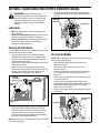
Operator’s Manual
Chipper Shredder Vacuum
IMPORTANT: Read safety rules and instructions carefully
Warning: This unit is equipped with an internal combustion engine and should not be used on or near any unimproved forest-covered, brushcovered or grass-covered land unless the engine’s exhaust system is equipped with a spark arrester meeting applicable local or state laws (if
any). If a spark arrester is used, it should be maintained in effective working order by the operator. In the State of California the above is required
by law (Section 4442 of the California Public Resources Code). Other states may have similar laws. Federal laws apply on federal lands. A spark
arrester for the muffler is available through your nearest engine authorized service dealer or contact the service department, P.O. Box 361131
Cleveland, Ohio 44136-0019.
TROY-BILT LLC P.O. BOX 361131 CLEVELAND, OHIO 44136-0019
PRINTED IN U.S.A.
FORM NO. 769-00170C.fm
(4/2004)
TABLE OF CONTENTS
Content
Page
Important Safe Operation Practices
3
Assembling Your Chipper Shredder Vacuum
5
Know Your Chipper Shredder Vacuum
7
Operating Your Chipper Shredder Vacuum
8
Adjusting Your Chipper Shredder Vacuum
9
Content
Page
Maintaining Your Chipper Shredder Vacuum 10
Trouble Shooting
13
Illustrated Parts List
14
Warranty
20
FINDING MODEL NUMBER
This Operator’s Manual is an important part of your new chipper shredder vacuum. It will help you
assemble, prepare and maintain the unit for best performance. Please read and understand what it says.
Before you start assembling your new equipment, please locate the model plate on the
equipment and copy the information from it in the space provided below. A sample model plate is
also given below. You can locate the model plate by standing behind the unit and looking down at
the frame below the engine. This information will be necessary to use the manufacturer’s
web site and/or help from the Customer Support Department or an authorized service dealer.
Copy the model number here:
www.troybilt.com
Copy the serial number here:
TROY-BILT LLC
P. O. BOX 3 6 1 1 3 1
CLEVELAND, OH 44136
330-558-7220
1-800-520-5520
CUSTOMER SUPPORT
Please do NOT return the unit to the retailer from where it was purchased, without first contacting Customer Support.
If you have difficulty assembling this product or have any questions regarding the controls, operation or
maintenance of this unit, you can seek help from the experts. Choose from the options below:
Visit troybilt.com for many useful suggestions. Click on Customer Support button and you will
get the four options reproduced here. Click on the appropriate button and help is immediately
available.
The answer you are
looking for could be just
a mouse click away!
The answer you are
looking for could be just
a mouse click away!
If you prefer to reach a Customer Support Representative, please call 1-800-520-5520.
Engine
Manual
The engine manufacturer is responsible for all engine-related issues with regards to
performance, power-rating, specifications, warranty and service. Please refer to the engine
manufacturer’s Owner’s/Operator’s Manual, packed separately with your unit, for more
information.
2
SECTION 1: IMPORTANT SAFE OPERATION PRACTICES
WARNING: This symbol points out important safety instructions which, if not followed, could endanger
the personal safety and/or property of yourself and others. Read and follow all instructions in this manual
before attempting to operate this machine. Failure to comply with these instructions may result in personal
injury. When you see this symbol - heed its warning.
WARNING: The Engine Exhaust from this product contains chemicals known to the State
of California to cause cancer, birth defects or other reproductive harm.
DANGER: This machine was built to be operated according to the rules for safe operation in this manual.
As with any type of power equipment, carelessness or error on the part of the operator can result in serious
injury. This machine is capable of amputating hands and feet and throwing objects. Failure to observe the
following safety instructions could result in serious injury or death.
Training
1.
2.
3.
4.
5.
6.
7.
8.
Read, understand, and follow all instructions on the
machine and in the manual(s) before attempting to
assemble and operate. Keep this manual in a safe place
for future and regular reference and for ordering
replacement parts.
Be familiar with all controls and their proper operation.
Know how to stop the machine and disengage them
quickly.
Never allow children under 16 years old to operate this
machine. Children 16 years old and over should read and
understand the operation instructions and safety rules in
this manual and should be trained and supervised by a
parent.
Never allow adults to operate this machine without
proper instruction.
Keep bystanders, helpers, pets, and children at least 75
feet from the machine while it is in operation. Stop
machine if anyone enters the area.
Never run an engine indoors or in a poorly ventilated
area. Engine exhaust contains carbon monoxide, an
odorless and deadly gas.
Do not put hands and feet near rotating parts or in the
feeding chambers and discharge opening. Contact with
the rotating impeller can amputate fingers, hands, and
feet.
Never attempt to unclog either the feed intake or
discharge opening, remove or empty vacuum bag, or
inspect and repair the machine while the engine is
running. Shut the engine off and wait until all moving
parts have come to a complete stop. Disconnect the
spark plug wire and ground it against the engine.
4.
5.
6.
Preparation
1.
2.
3.
Thoroughly inspect the area where the equipment is to
be used. Remove all rocks, bottles, cans, or other foreign
objects which could be picked up or thrown and cause
personal injury or damage to the machine.
Always wear safety glasses or safety goggles during
operation or while performing an adjustment or repair, to
protect eyes. Thrown objects which ricochet can cause
serious injury to the eyes.
Wear sturdy, rough-soled work shoes and close-fitting
slacks and shirts. Loose fitting clothes or jewelry can be
caught in movable parts. Never operate this machine in
bare feet or sandals. Wear leather work gloves when
feeding material in the chipper chute.
Before starting, check all bolts and screws for proper
tightness to be sure the machine is in safe working
condition. Also, visually inspect machine for any damage
at frequent intervals.
Maintain or replace safety and instructions labels, as
necessary.
To avoid personal injury or property damage use extreme
care in handling gasoline. Gasoline is extremely
flammable and the vapors are explosive. Serious
personal injury can occur when gasoline is spilled on
yourself or your clothes which can ignite. Wash your skin
and change clothes immediately.
a. Use only an approved gasoline container.
b. Extinguish all cigarettes, cigars, pipes, and other
sources of ignition.
c. Never fuel machine indoors.
d. Never remove gas cap or add while the engine is
hot or running.
e. Allow engine to cool at least two minutes before
refueling.
f. Never over fill fuel tank. Fill tank to no more than
1/2 inch below bottom of filler neck to provide
space for fuel expansion.
g. Replace gasoline cap and tighten securely.
h. If gasoline is spilled, wipe it off the engine and
equipment. Move machine to another area. Wait 5
minutes before starting engine.
i. Never store the machine or fuel container inside
where there is an open flame, spark, or pilot light
(e.g. furnace, water heater, space heater, clothes
dryer, etc.)
j. To reduce a fire hazard, keep machine free of
grass, leaves, or other debris build-up. Clean up
oil or fuel spillage and remove any fuel soaked
debris.
k. Allow machine to cool at least 5 minutes before
storing.
Operation
1.
3
Do not put hands and feet near rotating parts or in the
feeding chambers and discharge opening. Contact with
the rotating impeller can amputate fingers, hands, and
feet.
2.
3.
4.
4.
5.
6.
7.
8.
9.
10.
11.
12.
13.
14.
15.
Before starting the machine, make sure the chipper
chute, feed intake, and cutting chamber are empty and
free of all debris.
Thoroughly inspect all material to be shredded and
remove any metal, rocks, bottles, cans, or other foreign
objects which could cause personal injury or damage to
the machine.
If the impeller strikes a foreign object or and/or if your
machine should make an unusual noise or vibration, shut
the engine off immediately. Allow the impeller to stop;
disconnect the spark plug wire, ground it against the
engine and perform the following steps:
a. Inspect for damage.
b. Repair or replace any damaged parts.
c. Check for any loose parts and tighten to assure
continued safe operation.
Do not allow an accumulation of processed material to
build up in the discharge area. This can prevent proper
discharge and result in kickback of material through the
feed opening.
Do not attempt to shred or chip material larger than
specified on the machine or in this manual. Personal
injury or machine damage could result.
Never attempt to unclog either the feed intake or
discharge opening while the engine is running. Shut the
engine off, wait until all moving parts have stopped,
disconnect the spark plug wire and ground it against the
engine before clearing debris.
Never operate without vacuum bag and discharge chute
properly attached to the machine. Never empty or
change vacuum bag while the engine is running.
Zippered end of vacuum bag must be kept closed at all
times during operation.
Never operate without either the inlet nozzle or optional
hose attachment properly attached to the machine.
Never attempt to attach or change either attachment
while the engine is running.
Keep all guards, deflectors and safety devices in place
and operating properly.
Keep your face and body back and to the side of the
chipper chute while feeding material into the machine to
avoid accidental kickback injuries.
Never operate this machine without good visibility or
light. Always be sure of your footing and keep a firm hold
on the handles.
Do not operate this machine on a gravel surface.
Do not operate this machine while under the influence of
alcohol or drugs.
Muffler and engine become hot and can cause a burn. Do
not touch.
Never pick up or carry machine while the engine is
running.
stopped. Disconnect the spark plug wire and ground it
against the engine to prevent unintended starting.
4. Do not change the engine governor settings or
overspeed the engine. The governor controls the
maximum safe operating speed of the engine.
5. Maintain or replace safety and instruction labels, as
necessary.
6. Follow this manual for safe loading, unloading,
transporting, and storage of this machine.
7. Never store the machine or fuel container inside where
there is an open flame, spark or pilot light such as a water
heater, furnace, clothes dryer, etc.
8. Always refer to the operator’s manual for proper
instructions on off-season storage.
9. If the fuel tank has to be drained, do this outdoors.
10. Observe proper disposal laws and regulations for gas,
oil, etc. to protect the environment.
Your Responsibility
Restrict the use of this power machine to persons who
read, understand and follow the warnings and
instructions in this manual and on the machine.
NOTE: Not all safety labels shown may apply to your
chipper shredder vacuum.
Maintenance & Storage
1.
2.
3.
Never tamper with safety devices. Check their proper
operation regularly.
Check bolts and screws for proper tightness at frequent
intervals to keep the machine in safe working condition.
Also, visually inspect machine for any damage and
repair, if needed.
Before cleaning, repairing, or inspecting, stop the engine
and make certain the impeller and all moving parts have
4
SECTION 2: ASSEMBLING YOUR CHIPPER SHREDDER VACUUM
Unpacking
Attaching The Nozzle
•
•
•
•
•
Remove staples, break glue on top flaps, or cut
tape at carton end and peel along top flap to open
carton.
Remove loose parts if included with unit (i.e.,
operator’s manual, etc.)
Cut along corners, lay carton down flat, and remove
packing material.
Roll or slide unit out of carton and check carton
thoroughly for loose parts.
•
Remove three wing nuts from the front of the
chipper shredder vacuum.
Place nozzle in position over the three studs on unit
and secure with wing nuts just removed.
See Figure 2.
Wing
Nuts
Wing
Nut
Loose Parts In Carton
Following is the list of loose parts shipped with your
equipment. Compare the parts with the illustration in
Figure 1 to identify these items.
1.
2.
3.
4.
5.
6.
Nozzle
Nozzle
Bag
Chipper Chute
Tamper Plug
Safety Glasses (Not Shown)
Oil (Not Shown)
Figure 2
NOTE: The metal tab on the nozzle must depress the
safety switch button attached to the front of the chipper
shredder vacuum or the engine will not start.
Attaching the Chipper Chute
Bag
•
Nozzle
Loosen, but do not remove, the two hex bolts, flat
washers, and flange nuts which are secured to the
support bracket. See Figure 3.
Chipper
Chute
Hex Bolts
Chipper Chute
Tamper Plug
Figure 1
Flat
Washers
Before Assembly
IMPORTANT: This unit is shipped without gasoline or oil
in the engine. Be certain to service engine with gasoline
and oil as instructed in the accompanying engine
manual before operating your machine.
Support
Bracket
NOTE: Reference to right or left side of the equipment
is observed from the operating position, unless
otherwise stated.
Flange
Nuts
Figure 3
•
5
Remove the two flange nuts, hex bolts and saddle
washers which secure the right side of the upper
handle to the right side of the lower handle.
See Figure 4.
•
•
Remove the three hex nuts and bell washers from
the weld studs beside the opening on the right side
of the chipper-shredder vacuum. See Figure 4.
•
Flange Nuts
•
Attaching The Bag
Weld
Studs
•
Hex Nuts &
Hex Bolts &
Bell Washers
Saddle Washers
Place bag under the upper handle assembly and
slip the front opening on the bag over the discharge
chute, making certain it is over the rim on the
discharge chute. Follow direction of the arrows in
Figure 6.
Upper
Handle
Strap
Strap
Figure 4
•
Align the support bracket with the holes in the right
side of the upper and lower handles where the hex
bolts were just removed. Push up slightly on the
chipper chute in order to better align the holes in
the support bracket with the holes in the handles.
Replace the hex bolts, saddle washers and flange
nuts to affix the support bracket to the handle
assemblies. See Figure 5.
Follow by tightening all hardware securely first on
the chipper chute, then on the support bracket,
and finally on the handle.
Discharge
Chute
Place the chipper chute over the weld studs
keeping the slotted side towards the bottom.
Loosely secure with the three hex nuts and bell
washers that were removed earlier. Do not fully
tighten the hex nuts at this point in the assembly.
See Figure 5.
Strap
Chipper
Chute
Bag
Support
Bracket
Figure 6
Flange
Nuts
Hex Bolts &
Saddle Washers
Slot
•
Hex Nuts &
Bell Washers
Figure 5
6
Place the four straps on top of the bag over the
upper handle, hooking them on the studs to secure
in place. See Figure 6. Squeeze the clamp on the
drawstring and pull the drawstring tight. Release
the clamp.
SECTION 3: KNOW YOUR CHIPPER SHREDDER VACUUM
WARNING: Be familiar with all controls and their proper operation. Know how to stop the machine and
disengage them quickly.
Drive Clutch
Control
Tamper Plug
Chipper
Chute
Nozzle
Nozzle Door
Adjustment
Lever
Bag
Caster Locks
Figure 7
Vacuum/Chipper Bag
Drive Clutch Control
Collects shredded or chipped material fed through the
chipper chute or vacuumed up through the nozzle.
See Figure 7.
The drive clutch control is located on the upper handle
assembly. Squeezing the drive clutch control against
the upper handle engages the rear wheels. Release the
drive clutch control to slow down or stop the wheel
drive. See Figure 7.
Chipper Chute
Allow twigs and small branches up to 3” in diameter to
be fed into the impeller for chipping. See Figure 7.
Throttle Control Lever (Not Shown)
The throttle control lever is located on the engine. It
controls the engine’s speed and stops the engine.
Refer to the engine manual for further details.
Tamper Plug
This plug is inserted into the chipper chute to push
twigs and small branches towards the impeller blades
without endangering your hands.
Starter Handle (Not Shown)
The starter handle is located on the engine. Pull the
starter handle to start engine.
Caster Locks
The caster locks are located on top of each front caster
wheel. Refer to the Adjustment Section to position
wheel locks. See Figure 7.
Engine Controls
Refer to the engine manual for the location and function
of these controls.
Nozzle Door Adjustment Levers
The nozzle adjustment levers are located on each side
of the nozzle door. They are used to adjust the nozzle
door for ground clearance that will provide the best
performance for the operating conditions. See Figure 7.
Stopping the Engine
Nozzle
•
•
Yard waste such as leaves and pine needles can be
vacuumed up through the nozzle for shredding.
7
Move throttle control lever to STOP or OFF
position.
Disconnect spark plug wire from spark plug and
ground against the engine.
SECTION 4: OPERATING YOUR CHIPPER SHREDDER VACUUM
•
•
Read, understand, and follow all instructions and
warnings on the machine and in this manual before
operating. A pair of safety glasses has been
provided with this equipment.
NOTE: See your engine manual packed with your unit
for more detailed instructions.
WARNING: Always wear safety glasses
during operation or while performing any
adjustments or repairs. Thrown objects which
ricochet can cause serious injury to the eyes.
To Empty Bag
•
Gas & Oil Fill-Up
•
Service the engine with gasoline and oil as instructed in
the engine manual. Read instructions carefully.
•
•
•
Starting Engine
•
WARNING: Keep bystanders, helpers, pets,
and children at least 75 feet from the machine
before starting and while operating. Do not
operate this machine unless the discharge
chute and bag have been properly installed
and secured to the machine.
•
•
•
•
•
•
To engage the wheel drive, hold the drive clutch
control against the upper handle.
Release the drive clutch control to stop the rear
wheels from driving.
Release the drive clutch control to slow down when
negotiating an obstacle, making a turn, or stopping.
Engage control slowly to prevent the front wheels
from lifting up.
Using the Chipper Shredder Vacuum
•
Attach spark plug wire to spark plug. Make certain
the metal cap on the end of the spark plug is
fastened securely over metal tip on the spark plug.
Make certain drive clutch control is in the
disengaged (released) position.
Engines with choke lever: Move choke lever on
engine to CHOKE position. (A warm engine may
not require choking).
Engines with primer: Prime engine as instructed
in the engine manual.
Move engine throttle control lever to FAST or
START position.
Place one foot on the left rear wheel to prevent the
unit from skidding while starting.
Grasp starter handle and pull rope out slowly until
engine reaches start of compression cycle (rope
will pull slightly harder at this point).
•
Place both hands on top of upper handle to push
unit over yard waste. Yard waste such as leaves
and pine needles can be vacuumed up through the
nozzle for shredding.
After material has been shredded by the blades on
the impeller assembly, it will be discharged into
catcher bag. Do not attempt to shred or chip any
material other than vegetation found in a normal
yard (i.e. branches, leaves, twigs, etc.) Avoid
fibrous plants such as tomato vines until they are
thoroughly dried out. Materials such as stalks or
heavy branches up to 3” in diameter may be fed
into the chipper chute.
WARNING: Do not attempt to shred, chip, or
vacuum any material larger than specified on
the machine or in this manual. Personal injury
or damage to the machine could result.
IMPORTANT: The flail screen is located inside the
housing in the discharge area. If the flail screen
becomes clogged, remove and clean as instructed in
the maintenance section. For best performance, it is
also important to keep the chipper blade sharp.
NOTE: A noise will be heard at the start of the
compression cycle, which will continue to be heard till
the impeller reaches full speed.
•
Open the large zipper in the rear of the bag to
empty the contents. Be certain the zipper is closed
completely when operating the unit.
If bag is removed for any reason, follow instructions
for attaching the bag in the ASSEMBLY section.
To Engage Drive
WARNING: Use extreme care when
handling gasoline. Gasoline is extremely
flammable and the vapors are explosive. Never
fuel machine indoors or while the engine is hot
or running. Extinguish cigarettes, cigars, pipes,
and other sources of ignition.
•
Repeat until engine cranks. When engine starts,
move choke control (if equipped) gradually to RUN
position.
Tire Pressure (Pneumatic tires only)
Keeping a firm grip on the starter handle, pull rope
with a rapid, continuous, full arm stroke. Let the
rope rewind slowly.
Maximum tire pressure under any circumstance is 30
psi. Equal tire pressure should be maintained at all
times.
8
SECTION 5: ADJUSTING YOUR CHIPPER SHREDDER VACUUM
•
WARNING: Do not at any time make any
adjustments without first stopping engine,
disconnecting spark plug wire, and grounding it
against the engine.
Front Caster Wheels
Drive Clutch Cable
This chipper shredder vacuum is equipped with front
caster wheels. The casters can be locked in a straight
ahead position or to swivel freely.
•
Slide the height adjustment lever forward or
backward for adjusting the nozzle door upwards or
downwards. Height must be adjusted equally. In
general, raise the nozzle to vacuum a thick layer of
leaves and lower the nozzle for smooth surfaces.
See Figure 9.
Adjust the drive clutch control if:
Lift and place pins in the larger holes for locked or
straight ahead operation. See Figure 8.
a. Place pins in smaller holes to allow casters to
rotate freely.
b. Lock wheels in straight position when
operating on slopes.
•
Smaller Hole
(Rotate Freely)
•
a. the chipper shredder vacuum moves forward
with the drive clutch control disengaged,
b. it does not self-propel with the drive clutch
control engaged, or
c. drive belt is slipping (unit hesitates while
engine maintains the same speed).
Use the adjustment wheel located in the clutch
control housing to tighten or loosen the clutch
cable.
In addition, the adjustment wheel may also be used
to determine the position in which the drive clutch
control is engaged. If it is more comfortable to have
the drive engaged with the lever further away from
the handle, tighten the clutch cable. See Figure 10.
Larger Hole
(Locked)
Tighten
Adjustment
Wheel
Figure 8
Nozzle Door Height
The nozzle adjustment levers are located on each side
of the nozzle door. The nozzle door can be adjusted to
one of five positions, ranging from 1/2” to 3” ground
clearance, to provide best performance.
Loosen
Figure 10
Nozzle Door
Adjustment
Lever
Figure 9
9
SECTION 6: MAINTAINING YOUR CHIPPER SHREDDER VACUUM
•
WARNING: Before performing any
maintenance or repairs, stop the engine, wait
until the machine comes to a complete stop,
disconnect the spark plug wire and ground
against the engine to prevent unintended
starting.
Reattach the discharge chute assembly with the
hardware previously removed and attach the bag to
the unit.
Hex Bolts
Hex Nuts
Flail Screen
Lubrication
•
•
•
Wheels: Lubricate the rear wheels with light oil
once a season.
Nozzle Door Adjustment Levers: Lubricate each
adjustment lever once a season with light oil.
Front Caster Wheels: Grease fittings are located
on the front caster wheels to provide easy
lubrication of the swivel pins.
Cleaning the Flail Screen
Figure 12
If the discharge area becomes clogged, remove the flail
screen and clean area as follows:
•
•
•
•
Servicing the Blades
Stop the engine and make certain the chipper
shredder vacuum has come to a complete stop.
Disconnect spark plug wire from spark plug and
ground against the engine.
Remove the vacuum bag and tamper plug from the
equipment and save.
Remove the four self-tapping screws from the
bottom of the discharge chute, and the hex bolt, flat
washer and hex nut from the top. Remove the
discharge chute assembly. See Figure 11.
NOTE: When tipping the unit, empty the fuel tank and
keep the spark plug side up.
•
•
•
Hex Bolt
Flat Washer
Hex Nut
•
•
Discharge
Chute
•
Disconnect the spark plug wire and ground it
against the engine.
Remove the flail screen as instructed in the
previous section.
Remove plastic belt cover from front of the engine
by removing the two self-tapping screws. See
Figure 13.
Remove the access plate by removing two hex lock
nuts. See Figure 13.
Locate one of the chipper blades in the access
opening by rotating the impeller assembly by hand.
Remove the chipper blade using a 3/16” allen
wrench and a 1/2” wrench.
Remove other blade in the same manner to replace
or sharpen.
Access Plate
Self-Tapping
Screws
Self-Tapping
Screws
Lock Nuts
Figure 11
•
•
Remove the two hex bolts and hex nuts which
extend through the impeller housing. Lift the flail
screen from inside the housing. See Figure 12.
Clean the flail screen by scraping and/or washing
with water, and reinstall the screen.
Belt Cover
NOTE: Be certain to reassemble the flail screen with
the curved side down.
Figure 13
10
•
WARNING: Use caution when replacing the
blades. Wear heavy gloves to avoid injury while
handling the weld bolts, housing or the blades.
•
•
When sharpening blades, follow the original angle
of grind. Also, make sure to remove an equal
amount from each blade and torque hardware to
250 - 300 in.lb.
•
Remove the two hex bolts and hex lock nuts which
extend through the housing. Lift the flail screen out
of the housing. Refer to Figure 11.
Remove the outer housing and housing blades by
removing the fourteen self-tapping screws.
Remove the hex bolt, lock washer, and flat washer
that secures the impeller assembly to the
crankshaft. See Figure 15.
Hex Bolt
Lock Washer
Flat Washer
NOTE: Make sure that blades are reassembled with the
sharp edge facing upward.
Impeller
Assembly
Inner
Housing
Replacing the Belt
NOTE: Because the engine on this equipment has a
tapered crankshaft, a special impeller removal tool (part
number 753-0900) is required to remove the impeller
assembly. Contact your local service dealer for this.
•
•
•
•
•
•
•
•
•
Disconnect the spark plug wire and ground it away
from the spark plug.
Drain the gasoline and oil from the chipper
shredder vacuum.
Remove the three wing nuts that secure the nozzle
to the outer housing and remove the nozzle. Refer
to Figure 2.
Remove the vacuum bag from the unit.
Remove the discharge chute as instructed in
“Cleaning The Flail Screen.”
Remove the plastic belt cover from front of the
engine by removing two self-tapping screws. Refer
to Figure 13.
Tip the unit backward so that it rests on the
handles.
Remove the lower belt guard by removing the two
self-tapping screws. See Figure 14.
Remove the safety switch from front of the outer
housing by removing the two self-tapping screws.
See Figure 14.
Housing
Blades
Figure 15
•
•
•
Thread the special impeller tool into the crankshaft.
Stop when the impeller assembly can move on the
crankshaft.
If the old belt is still on the unit, cut belt to remove
from unit.
Remove impeller assembly from the crankshaft and
unthread the impeller tool from the impeller.
Hex Bolts
Safety
Switch
Self-Tapping
Screw
Hex Bolts
Lower
Belt Guard
Figure 16
•
•
Self-Tapping
Screws
Figure 14
11
Remove the inner housing and mounting adapter
by removing the five hex bolts and two hex nuts.
See Figure 16.
Insert new belt between the frame and the
transmission pulley. See Figure 17. (You may have
to slightly pry the frame away from the pulley with a
screwdriver for this.)
Belt Guard
Spring
Outer
Housing
Mounting
Adapter
Idler
Bracket
Idler
Frame
Transmission Pulley
Holes for
Screwdrivers
Figure 17
•
•
•
•
•
•
•
•
•
•
Press down on the belt guard spring by the idler
pulley, and release the spring from the slot on the
idler bracket.
Place the belt on the idler pulley and place belt
guard spring back into the slot on the idler bracket.
See Figure 17.
Place the mounting adapter against the engine and
make sure the hole in the mounting adapter is
facing up.
Place the inner housing against the mounting
adapter and the frame. Secure with five hex bolts
and two hex nuts previously removed. Refer to
Figure 16.
Slide the impeller assembly onto the crankshaft
and place a screwdriver under the belt. Turn the
impeller assembly counterclockwise to place the
belt into the slot on the impeller. Make sure the belt
is routed inside all belt guards.
Secure impeller assembly to crankshaft using hex
bolt, lock washer, and flat washer previously
removed. Torque bolt between 550-700 in. lb.
Place the housing blades against the inner
housing. Refer to Figure 15.
Place the outer housing against the inner housing.
See Figure 18. Insert two screwdrivers into the
holes to hold the blades in place while attaching the
outer housing.
Secure with the 14 self-tapping screws, previously
removed. Insert all screws first before tightening.
Reassemble the flail screen, discharge chute,
nozzle and the bag. (For reassembly, follow
instructions on previous page in reverse order.)
Figure 18
Engine
A few general recommendations are given below.
However, refer to the accompanying engine manual for
further details.
•
•
•
Check engine oil level before each use as
instructed in the engine manual. Read and follow
instructions carefully.
Clean air cleaner every 25 hours under normal
conditions or once a season. Clean every few hours
under extremely dusty conditions. To service the air
cleaner, refer to the engine manual.
The spark plug should be cleaned and the gap
reset once a season. Check engine manual for
correct plug type and gap specifications.
Storing Your Chipper Shredder Vacuum
•
•
•
•
Clean the equipment thoroughly.
Wipe equipment with an oiled rag to prevent rust.
Refer to engine manual for correct engine storage
instructions
Store unit in a clean, dry area. Do not store next to
corrosive materials such as fertilizer.
WARNING: Never store the machine or fuel
container indoors where there is an open
flame, spark, or pilot light such as on a water
heater, furnace, clothes dryer, or other gas
appliance.
12
SECTION 7: TROUBLESHOOTING
Problem
Engine fails to start
Engine runs erratic
Cause
Remedy
1. Spark plug wire disconnected.
2. Fuel tank empty or stale fuel.
3. Throttle control lever not in correct
starting position. (If Equipped)
4. Choke not in CHOKE position.
(If Equipped)
5. Blocked fuel line.
6. Faulty spark plug.
1. Connect wire to spark plug.
2. Fill tank with clean, fresh gasoline.
3. Move throttle lever to FAST position.
1. Spark plug wire loose.
2. Unit running on CHOKE.
(If Equipped)
3. Blocked fuel line or stale fuel.
1. Connect and tighten spark plug wire.
2. Move choke lever to OFF position.
4. Move choke to CHOKE position.
5. Clean fuel line.
6. Clean, adjust gap, or replace.
4. Water or dirt in fuel system.
5. Dirty air cleaner.
6. Carburetor out of adjustment.
3. Clean fuel line; fill tank with clean, fresh
gasoline.
4. Drain fuel tank. Refill with fresh fuel.
5. Clean or replace air cleaner.
6. See authorized service dealer.
Too much vibration
1. Loose parts or damaged impeller.
1. See authorized service dealer.
Engine overheats
1. Engine oil level low.
2. Dirty air cleaner.
3. Carburetor not adjusted properly.
1. Fill crankcase with proper oil.
2. Clean or replace air cleaner.
3. See authorized service dealer.
Occasional skip (hesitates) 1. Spark plug gap too close.
at high speed
1. Adjust gap to.030”.
Unit does not discharge
1. Stop engine immediately and
disconnect spark plug wire. Clean flail
screen and inside of discharge opening.
2. Stop engine and disconnect spark plug
wire. Remove lodged object.
3. Always run engine at full throttle.
4. Empty bag.
1. Discharge chute clogged.
2. Foreign object lodged in impeller.
3. Low engine RPM.
4. Vacuum bag is full.
1. Low engine RPM.
Rate of discharge slows
2. Chipper blade dull.
considerably or
composition of discharged
material changes
1. Always run engine at full throttle.
2. Replace chipper blade or see your
authorized service dealer.
NOTE: For repairs beyond the minor adjustments listed above, contact your nearest authorized service dealer.
13