1
Toshiba Personal Computer
QosmioF50
Maintenance Manual
TOSHIBA CORPORATION
Copyright
© 2008 by Toshiba Corporation. All rights reserved. Under the copyright laws, this manual
cannot be reproduced in any form without the prior written permission of Toshiba. No patent
liability is assumed with respect to the use of the information contained herein.
Toshiba Personal Computer Qosmio Maintenance Manual
First edition June. 2008
Disclaimer
The information presented in this manual has been reviewed and validated for accuracy. The
included set of instructions and descriptions are accurate for the TOSHIBA Qosmio at the
time of this manual's production. However, succeeding computers and manuals are subject to
change without notice. Therefore, Toshiba assumes no liability for damages incurred directly or
indirectly from errors, omissions, or discrepancies between any succeeding product and this
manual.
Trademarks
IBM is a registered trademark and IBM PC is a trademark of International
Business Machines Corporation.
Intel, Intel SpeedStep, Intel® CoreTM, Celeron and Centrino are trademarks
or registered trademarks of Intel Corporation.
Windows, Microsoft and Windows Vista® are registered trademarks of
Microsoft Corporation.
Photo CD is a trademark of Eastman Kodak.
Bluetooth is a trademark or registered trademark owned by its proprietor
and used by TOSHIBA under license.
Memory Stick is a registered trademark and i.LINK is a trademark of Sony
Corporation.
DVD MovieFactory is a registered trademarks of Ulead Systems, Inc.
Labelflash is a trademark of YAMAHA CORPORATION.
Manufactured under license from Dolby Laboratories.
Dolby and the double-D symbol are trademarks of Dolby Laboratories.
Dolby Home Theater is a trademark of Dolby Laboratories.
PalmCheck and TouchPad are trademarks of Synaptics Incorporated.
ExpressCard is a trademark of PCMCIA.
ConfigFree is a trademark of Toshiba Corporation.
Wi-Fi is a registered trademark of the Wi-Fi Alliance.
Secure Digital and SD are trademarks of SD Card Association.
MultiMediaCard and MMC are trademarks of MultiMediaCard Association.
xD-Picture Card is a trademark of FUJIFILM Corporation.
Other trademarks and registered trademarks not listed above may be used
in this manual.
ii
Qosmio
0 Maintenance Manual
Preface
This maintenance manual describes how to perform hardware service maintenance for the
Toshiba Personal Computer Qosmio 0, referred to as the Qosmio 0 Series in this manual.
The procedures described in this manual are intended to help service technicians isolate faulty
Field Replaceable Units (FRUs) and replace them in the field.
SAFETY PRECAUTIONS
Four types of messages are used in this manual to bring important information to your attention.
Each of these messages will be italicized and identified as shown below.
DANGER: “Danger” indicates the existence of a hazard that could result in death or
serious bodily injury if the safety instruction is not observed.
WARNING: “Warning” indicates the existence of a hazard that could result in bodily
injury if the safety instruction is not observed.
CAUTION: “Caution” indicates the existence of a hazard that could result in property
damage if the safety instruction is not observed.
NOTE: “Note” contains general information that relates to your safe maintenance
service.
Improper repair of the computer may result in safety hazards. Toshiba requires service
technicians and authorized dealers or service providers to ensure the following safety precautions
are adhered to strictly.
Be sure to fasten screws securely with the right screwdriver. If a screw is not fully
fastened, it could come loose, creating a danger of a short circuit, which could cause
overheating, smoke or fire.
If you replace the battery pack or RTC battery, be sure to use only the same model battery
or an equivalent battery recommended by Toshiba. Installation of the wrong battery can
cause the battery to explode.
Qosmio
Maintenance Manual
iii
The manual is divided into the following parts:
Chapter 1
Hardware Overview describes the Qosmio 0 system unit and each FRU.
Chapter 2
Troubleshooting Procedures explains how to diagnose and resolve FRU
problems.
Chapter 3
Test and Diagnostics describes how to perform test and diagnostic
operations for maintenance service.
Chapter 4
Replacement Procedures describes the removal and replacement of the
FRUs.
Appendices
The appendices describe the following:
Handling the LCD module
Board layout
Pin assignments
Keyboard scan/character codes
Key layout
Screw torque list
Reliability
Conventions
This manual uses the following formats to describe, identify, and highlight terms and operating
procedures.
Acronyms
On the first appearance and whenever necessary for clarification, acronyms are enclosed in
parentheses following their definition. For example:
Read Only Memory (ROM)
Keys
Keys are used in the text to describe many operations. The key top symbol as it appears on the
keyboard is printed in boldface type.
Key operation
iv
Qosmio
0 Maintenance Manual
Some operations require you to simultaneously use two or more keys. We identify such
operations by the key top symbols separated by a plus (+) sign. For example, Ctrl + Pause
(Break) means you must hold down Ctrl and at the same time press Pause (Break). If three
keys are used, hold down the first two and at the same time press the third.
User input
Text that you are instructed to type in is shown in the boldface type below:
DISKCOPY A: B:
The display
Text generated by the computer that appears on its display is presented in the typeface below:
Format complete
System transferred
Qosmio
Maintenance Manual
v
Table of Contents
Chapter 1
Hardware Overview
1.1
Features..............................................................................Error! Bookmark not defined.
1.2
2.5-inch HDD ....................................................................Error! Bookmark not defined.
1.3
DVD Super Multi (+-R Double Layer)..............................Error! Bookmark not defined.
1.4
Power Supply.....................................................................Error! Bookmark not defined.
1.5
Batteries .............................................................................Error! Bookmark not defined.
1.5.1
Main Battery.......................................................Error! Bookmark not defined.
1.5.2
Battery Charging Control ....................................Error! Bookmark not defined.
1.5.3
RTC Battery ........................................................Error! Bookmark not defined.
Chapter 2
Troubleshooting Procedures
2.1
Troubleshooting Introduction ........................................ Error! Bookmark not defined.
2.2
Troubleshooting Flowchart
…………………………………………………………… Error! Bookmark not
defined.
2.3
Power Supply Troubleshooting .......................................Error! Bookmark not defined.
2.4
Display Troubleshooting............................................... Error! Bookmark not defined.
2.5
Keyboard Troubleshooting ........................................... Error! Bookmark not defined.
2.6
External USB Devices Troubleshooting....................... Error! Bookmark not defined.
2.7
TV-tuner Failure Troubleshooting................................ Error! Bookmark not defined.
2.8
TouchPad Troubleshooting........................................... Error! Bookmark not defined.
2.9
Speaker Troubleshooting .............................................. Error! Bookmark not defined.
2.10
Optical drive troubleshooting ....................................... Error! Bookmark not defined.
2.
Modem Troubleshooting ……………………………………………………………. Error! Bookmark not defined.
vi
Qosmio
0 Maintenance Manual
2.12
Express card Troubleshooting.......................................Error! Bookmark not defined.
2.13
IEEE 1394 Troubleshooting..........................................Error! Bookmark not defined.
2.14
Wireless LAN Troubleshooting ....................................Error! Bookmark not defined.
2.15
Camera troubleshooting ................................................Error! Bookmark not defined.
2.16
Bluetooth Troubleshooting…………………...…………………………….………..
Error! Bookmark not defined.
2.17
7 in 1 card
Troubleshooting……………………………………………………..……Error!
Bookmark not defined.
2.18
HDD Troubleshooting………………………………………………………………..
Error! Bookmark not defined.
2.19
CRT failure Troubleshooting
………………………………………………………. Error! Bookmark not defined.
2.20
HDMI Troubleshooting ……………………………………………………………...
Error! Bookmark not defined.
2.21
SPDIF Troubleshooting ………….………………………………………………….
Error! Bookmark not defined.
2.22
MIC Troubleshooting ……………………………………………………………….
Error! Bookmark not defined.
2.23
Finger Troubleshooting ……………………………………………………………..
Error! Bookmark not defined.
2.24
FM tuner Troubleshooting …………………………………………………………..
Error! Bookmark not defined.
2.25
E-SATA Troubleshooting ………………………………………….………………..
Error! Bookmark not defined.
2.26
Felica Troubleshooting ………………………….…………………………………..
Error! Bookmark not defined.
2.27
TMA Troubleshooting …………………………….………….……………………..
Error! Bookmark not defined.
Qosmio
Maintenance Manual
vii
2.28
UWB Troubleshooting ………..……………………………………………………..
Error! Bookmark not defined.
2.29
IR-blaster Troubleshooting ………..…………………………………………….…..
Error! Bookmark not defined.
2.30
GPS Troubleshooting ………………………………………………………………..
Error! Bookmark not defined.
Chapter 3
Tests and Diagnostics
3.1
The Diagnostic Test .........................................................Error! Bookmark not defined.
3.2
Executing the Diagnostic Test .........................................Error! Bookmark not defined.
3.3
Display Configuration .................................................. Error! Bookmark not defined.
3.4
Beep sound Test...............................................................Error! Bookmark not defined.
3.5
Fan ON/OFF Test ......................................................... Error! Bookmark not defined.
3.6
Main Battery Charge Test ..............................................Error! Bookmark not defined.11
3.7
FDD Test ................... …Error! Bookmark not defined.Error! Bookmark not defined.
3.8
Computrace Check.........................................................Error! Bookmark not defined.14
3.9
Keyboard Test................ Error! Bookmark not defined.Error! Bookmark not defined.
3.10
Mouse (Pad) Test ...........................................................Error! Bookmark not defined.17
3.11
LCD Pixels Mode Test ..................................................Error! Bookmark not defined.18
3.12
Magnetic switch Test .....................................................Error! Bookmark not defined.19
3.13
LAN Test .......................................................................Error! Bookmark not defined.21
3.14
RTC Test........................................................................Error! Bookmark not defined.24
3.15
Read 1394 GUID ...........................................................Error! Bookmark not defined.25
3.16
Speaker EQ
Check…………...………….…….……………..……………...…….......Error!
Bookmark not defined.26
3.17
Button
Test…………..……………………….………….……………….….….…… Erro
r! Bookmark not defined.26
3.18
viii
HDCP Key Check ..........................................................Error! Bookmark not defined.27
Qosmio
0 Maintenance Manual
3.19 Memory
check ...….. ……………….………………………..…………………….....Error! Bookmark
not defined.29
3.20 1st HDD
Test ……………………………....…………….……………....….……… Error! Bookmark
not defined.30
3.21 2nd HDD
Test ……………………………....…………….……………....….……… Error! Bookmark
not defined.32
3.22 RDMI
Test ……………...………………………….………………...…..……………Error! Bookmark
not defined.35
3.23
WDMI Test …………….…………………………….…………….…....….…………36
3.24
Memory R/W Test .…….…………………………….…………….…....….…………38
Chapter 4
4.1
Replacement Procedures
General .............................................................................. Error! Bookmark not defined.
Safety Precautions .......................................................... Error! Bookmark not defined.
Before You Begin .............................................................. Error! Bookmark not defined.
Disassembly Procedures .................................................... Error! Bookmark not defined.
Assembly Procedures......................................................... Error! Bookmark not defined.
Tools and Equipment......................................................... Error! Bookmark not defined.
Screw Tightening Torque .................................................. Error! Bookmark not defined.
Colors of Screw Shanks..................................................... Error! Bookmark not defined.
Symbols of Screws on the Computer Body....................... Error! Bookmark not defined.
Symbol examples............................................................... Error! Bookmark not defined.
4.2
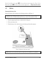
Battery ............................................................................... Error! Bookmark not defined.
Removing the Battery Pack ............................................... Error! Bookmark not defined.
Installing the Battery Pack ................................................. Error! Bookmark not defined.
4.3
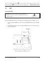
HDD .................................................................................. Error! Bookmark not defined.
Removing the HDD ........................................................... Error! Bookmark not defined.
Installing the HDD............................................................. Error! Bookmark not defined.
4.4
Qosmio
Memory ............................................................................. Error! Bookmark not defined.
Maintenance Manual
ix
Removing the Optional Memory .......................................Error! Bookmark not defined.
Installing the Optional Memory .........................................Error! Bookmark not defined.
4.5
Express Card......................................................................Error! Bookmark not defined.
Removing the Optional Express Card or PC Card.............Error! Bookmark not defined.
Installing the Optional Express Card or PC Card ..............Error! Bookmark not defined.
4.6
Optional Memory Card ......................................................Error! Bookmark not defined.
Removing the Optional Memory Card...............................Error! Bookmark not defined.
Installing the Optional Memory Card ................................Error! Bookmark not defined.
4.7
Keyboard Cover and Keyboard..........................................Error! Bookmark not defined.
Removing the Keyboard Cover and Keyboard ..................Error! Bookmark not defined.
Installing the keyboard Cover and Keyboard .....................Error! Bookmark not defined.
4.8
ODD...................................................................................Error! Bookmark not defined.
Removing the ODD Bay Module.......................................Error! Bookmark not defined.
Installing the ODD Bay Module ........................................Error! Bookmark not defined.
Disassembling the ODD Drive...........................................Error! Bookmark not defined.
Assembling the ODD Drive ...............................................Error! Bookmark not defined.
4.9
Top Cover ..........................................................................Error! Bookmark not defined.
Removing the Top Cover...................................................Error! Bookmark not defined.
Installing the Top Cover.....................................................Error! Bookmark not defined.
4.10
Display Assembly ..............................................................Error! Bookmark not defined.
Removing the Display Assembly.......................................Error! Bookmark not defined.
Installing the Display Assembly.........................................Error! Bookmark not defined.
4.11
Modem/FM Card & Mini Cards ........................................Error! Bookmark not defined.
Removing the Modem/FM card and Mini cards ................Error! Bookmark not defined.
Installing the Modem/FM Card & Mini Cards ..................Error! Bookmark not defined.
4.12
Speakers .............................................................................Error! Bookmark not defined.
Removing the Speakers......................................................Error! Bookmark not defined.
Installing the Speakers .......................................................Error! Bookmark not defined.
4.13
Touch Pad and Finger Print Board ....................................Error! Bookmark not defined.
Removing the Touch Pad and Finger Print Board .............Error! Bookmark not defined.
Installing the Touch Pad and Finger Print Board ...............Error! Bookmark not defined.
x
Qosmio
0 Maintenance Manual
4.14
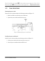
Power Switch Board.......................................................... Error! Bookmark not defined.
Removing the power switch .............................................. Error! Bookmark not defined.
Installing the power switch board...................................... Error! Bookmark not defined.
4.15
VR board ........................................................................... Error! Bookmark not defined.
Removing the VR board .................................................... Error! Bookmark not defined.
Installing the VR board...................................................... Error! Bookmark not defined.
4.16
Bluetooth Card .................................................................. Error! Bookmark not defined.
Removing the Bluetooth card ............................................ Error! Bookmark not defined.
Installing the Bluetooth card.............................................. Error! Bookmark not defined.
4.17
Wire Bridge ....................................................................... Error! Bookmark not defined.
Removing the Wire Bridge................................................ Error! Bookmark not defined.
Installing the Wire Bridge ................................................. Error! Bookmark not defined.
4.18
VGA Module/Cooler......................................................... Error! Bookmark not defined.
Removing the VGA Module/Cooler.................................. Error! Bookmark not defined.
Installing the VGA Module/Cooler ................................... Error! Bookmark not defined.
4.19
IR Blaster Board ................................................................ Error! Bookmark not defined.
Removing the IR Blaster Board......................................... Error! Bookmark not defined.
Installing the IR Blaster Board .......................................... Error! Bookmark not defined.
4.20
TV Tuner Card .................................................................. Error! Bookmark not defined.
Removing the TV Tuner Card ........................................... Error! Bookmark not defined.
Installing the TV Tuner Card............................................. Error! Bookmark not defined.
4.21
System Board .................................................................... Error! Bookmark not defined.
Removing the System Board ............................................. Error! Bookmark not defined.
Installing the System Board............................................... Error! Bookmark not defined.
4.22
TMA, CPU Fan and Cooling Module ............................... Error! Bookmark not defined.
Removing the TMA, CPU Fan and Cooling Module........ Error! Bookmark not defined.
Installing the TMA, CPU Fan and Cooling Module.......... Error! Bookmark not defined.
4.23
CPU ................................................................................... Error! Bookmark not defined.
Removing the CPU............................................................ Error! Bookmark not defined.
Installing the CPU ............................................................. Error! Bookmark not defined.
4.24
Qosmio
Sub-woofer ........................................................................ Error! Bookmark not defined.
Maintenance Manual
xi
Removing the Sub-woofer .................................................Error! Bookmark not defined.
Installing the Sub-woofer...................................................Error! Bookmark not defined.
4.25
RJ11/FM Tuner and TV Tuner ..........................................Error! Bookmark not defined.
Removing RJ11/FM Tuner and TV Tuner.........................Error! Bookmark not defined.
Installing the RJ11/FM Tuner and TV Tuner ....................Error! Bookmark not defined.
4.26
BKS....................................................................................Error! Bookmark not defined.
Removing the BKS ............................................................Error! Bookmark not defined.
Installing the BKS ..............................................................Error! Bookmark not defined.
4.27
Display Mask .....................................................................Error! Bookmark not defined.
Removing the Display Mask ..............................................Error! Bookmark not defined.
Installing the Display Mask................................................Error! Bookmark not defined.
4.2LCD Module and FL Inverter Board ......................Error! Bookmark not defined.
Removing the LCD Module and FL Inverter Board ..........Error! Bookmark not defined.
Installing the LCD Module and FL Inverter Board............Error! Bookmark not defined.
4.29
CCD Board, MIC and Antenna..........................................Error! Bookmark not defined.
Removing the CCD Board, MIC and Antenna ..................Error! Bookmark not defined.
Installing the CCD Board, MIC and Antenna ....................Error! Bookmark not defined.
xii
Qosmio
0 Maintenance Manual
Appendices
Appendix A
Handling the LCD Module.................................................................................. A-1
Appendix B
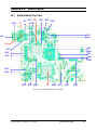
Board Layout ....................................................................................................... B-1
Appendix C
Pin Assignments.................................................................................................. C-1
Appendix D
Keyboard Scan/Character Codes......................................................................... D-1
Appendix E
Key Layout .......................................................................................................... E-1
Appendix F
Series Screw Torque List .....................................................................................F-1
Appendix G
Reliability ............................................................................................................ G-1
Qosmio
Maintenance Manual
xiii
Chapter 1
Hardware Overview
1 Hardware Overview
Qosmio F50 Maintenance Manual
1-ii
Error! Use the Home tab to apply 2 to the text that you want to appear here.
Overview
Chapter 1
1 Hardware
Contents
1.1
Features...................................................................................................................1-1
1.2
2.5-inch HDD .......................................................................................................1-13
1.3
DVD Super Multi (+-R Double Layer).................................................................1-15
1.4
Power Supply........................................................................................................1-16
1.5
Batteries ................................................................................................................1-18
1.5.1
Main Battery..........................................................................................1-18
1.5.2
Battery Charging Control ......................................................................1-18
1.5.3
RTC Battery ..........................................................................................1-19
Qosmio F50 Maintenance Manual
1-iii
1 Hardware Overview
Figures
Figure 1-1A
ID Parts Description Placement Part A ..........................................................1-8
Figure 1-2
SATA HDD..................................................................................................1-13
Figure 1-3
DVD Super Multi Drive...............................................................................1-15
Tables
Table 1-1
HDD Specifications......................................................................................1-13
Table 1-2
DVD Super Multi Drive Specifications .......................................................1-15
Table 1-3
Quick/Normal Charging Time......................................................................1-18
Qosmio F50 Maintenance Manual
1-iv
Error! Use the Home tab to apply 2 to the text that you want to appear here. Error! Use the
Home tab to apply 2 to the text that you want to appear here.
1.1
1 Hardware Overview
Features
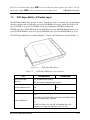
The Toshiba Qosmio F50 a full size notebook PC based on the Dual Core Processor, providing
high-speed processing capabilities and advanced features. The computer employs a Lithium Ion
battery that allows it to be battery-operated for a longer period of time. The display uses 15.4inch WXGA LCD panel. The PGA socket supports BTO for the CPU so that the system can be
designed to suit your needs.
The computer has the following features:
Processor (BTO)
The computer is equipped with one of the following Intel® processors.
Intel® Dual CoreTM 2 Duo Processor
Memory (BTO)
The computer has two SODIMMs slot comes standard with 512MB/1GB/2GB/4GB,
accepting BTO for your memory requirements. It can incorporate up to 8 GB of main
memory. It supports DDR2 at 667/800MHz.
Battery Pack
The computer is powered by one rechargeable and removable Lithium Ion battery pack. The
capacity can be either 8-cell or 4-cell, depending on the model of the computer.
RTC Battery
The internal RTC battery backs up the Real Time Clock and calendar.
Hard Disk Drive (HDD) (BTO)
The computer accommodates 9.5 mm and 12.5 mm two kinds of height HDD types with
following storage capacities:
160/250/320 GB (9.5 mm thick) SATA (5,400rpm)
160/200 GB (9.5 mm thick) SATA (7,200rpm)
500 GB (12.5 mm thick) SATA (5,400rpm)
300/400/500 GB (12.5 mm thick) SATA (4,200rpm)
Qosmio F50 Maintenance Manual
1-1
1 Hardware Overview
Error! Use the Home tab to apply 2 to the text that you want to
appear here. Error! Use the Home tab to apply 2 to the text that you want to appear here.
Qosmio F50 Maintenance Manual
1-2
Error! Use the Home tab to apply 2 to the text that you want to appear here. Error! Use the
Home tab to apply 2 to the text that you want to appear here.
1 Hardware Overview
ODD (BTO)
12.7mm height DVD Super Multi drive supporting ±R Double Layer
12.7mm height DVD Super Multi drive supporting IR Double Layer w/ Labelflash
Display (BTO)
The LCD displays available come with one of following types:
15.4” WXGA CSV color display, resolution 1280x800
15.4” WXGA CSV color display, resolution 1440x900
15.4” WXGA CSV with 2-lamp color display 1280x800
Graphics (BTO)
Intel GM45 integrated graphic or PM45 with NB9E-GS/NB9P-GS/NB9P-GE/NB9M-GE
(depending on model).
Keyboard
The computer is equipped with a Toshiba standard 300mm keyboard, which has 86/87 keys
support without stick-point. It is a Vista compliance keyboard, where you may find
Windows key and application keys.
Pointing Device
The integrated Wide Touch Pad and two control buttons in the palm rest allow control of
the on-screen pointer and support functions such as the scrolling of windows.
External Monitor Port
The analog VGA port provides support for VESA DDC2B compatible functions. A WDDM
driver is ready for Vista.
Universal Serial Bus (USB) Ports
The computer has three USB 2.0 ports. It is supported to daisy-chain a maximum of 127
USB devices. The serial data transfer rate is 480 Mbps or 12 Mbps and 1.5 Mbps. These
ports support PnP installation and hot plugging. They also support Sleep and Charge
function.
Qosmio F50 Maintenance Manual
1-3
1 Hardware Overview
Error! Use the Home tab to apply 2 to the text that you want to
appear here. Error! Use the Home tab to apply 2 to the text that you want to appear here.
Qosmio F50 Maintenance Manual
1-4
Error! Use the Home tab to apply 2 to the text that you want to appear here. Error! Use the
Home tab to apply 2 to the text that you want to appear here.
1 Hardware Overview
IEEE1394
This port allows high-speed data transfer to take place between the computer and external
devices such as digital video cameras. The computer is supported by Jmicron JMB380
controller.
Express Card Slot
The internal Express Card slot is a universal slot. This slot supports ExpressCard/54 and the
slot is covered with a shutter door. It also supports USB/PCI Express signals.
Bridge Media Slot
This slot allows you to insert SD, MiniSD/ MicroSD (through adapter), Memory
Stick/Memory Stick Duo (through adaptor), Memory Stick Pro/Memory Stick Duo (through
adaptor), XD and MMC memory card. It supports High speed SD, SDHC and SDIO. An I/O
port heel cover is needed. This model does not support CF cards.
Sound system
The integrated sound system provides support for the computer's internal speakers and
microphone, as allowing an external microphone and headphones to be connected via the
appropriate jacks.
Internal Camera
It supports 1.3M pixels with Auto Macro. It comes with blue LED. The internal microphone
is BTO with the internal camera. The microphone comes with echo cancellation. This
camera is not a rotation type.
HDMI Out Port (BTO)
HDMI 1.3 out port can connect with Type A connector HDMI cable. One HDMI cable can
send and receive video, audio and control signals.
Headphones/S/PDIF/Line out Jack
This jack connects digital speakers or a stereo headphone (16 ohm minimum). When
connected to a digital speaker or headphones, the internal speaker is automatically disabled.
This jack can be used also as S/PDIF jack and enables connection of optical digital
correspondence apparatus.
Qosmio F50 Maintenance Manual
1-5
1 Hardware Overview
Error! Use the Home tab to apply 2 to the text that you want to
appear here. Error! Use the Home tab to apply 2 to the text that you want to appear here.
Microphone/ Line-in Jack
A 3.5mm mini microphone jack enables connection of a three-conductor microphone for
monaural input and also enables the connection of a stereo device for audio input.
TV Antenna Port
The TV Antenna Port lets you connect a TV Antenna. This supports BTO NTSC/PAL/
SECAM antenna connector.
LAN (BTO)
The computer has built-in support for Gigabit Ethernet LAN (1000 megabits per second,
1000BASE-T). It is a Realtek 8111 for Gigabit LAN. It is pre-installed as a standard device
in some markets.
Wireless LAN (BTO)
Some computers in this series are equipped with a Wireless LAN card. This WLAN module
may come in with the following types (depending on the model):
Intel 802.11a/g (Echo Peak 1x2 & Shirley Peak 1x2)
Intel 802.11a/g/n (Echo Peak 3x3 Shirley Peak 3x3)
Atheros 802.11a/g (XB62L 1x2), b/g (XB63L 1x2), a/b/g/n (XB72 2x3), a/b/g/n (XB92
2x2)
Intel WiMAX 802.16e (Echo Peak 3x3)
Internal Modem (BTO)
Some models are equipped with the integrated modem. The integrated modem provides
capability for data and fax communications that support the V.90 (V.92) standards and
includes a modem jack for connection to the telephone line. Please note that both the V.90
and V.92 standards are only supported in the USA, Canada, United Kingdom, France,
Germany and Australia - only the V.90 standard is supported in other regions. You should
also be aware that the speed of data and fax transfer will depend on the analog telephone
line conditions. The integrated model is only installed as a standard device in some markets.
This internal modem comes with MDC 1.5 solution (Azalia interface) and is exclusive with
FM Turner.
Qosmio F50 Maintenance Manual
1-6
Error! Use the Home tab to apply 2 to the text that you want to appear here. Error! Use the
Home tab to apply 2 to the text that you want to appear here.
1 Hardware Overview
Bluetooth (BTO)
Some computers in this series offer Bluetooth wireless communication functionality which
eliminates the need for cables between electronic devices such as computers and printers.
When implemented, Bluetooth provides a fast, reliable and secure means to achieve wireless
communication in a small space. This module is Version 2.1 + EDR (Antenna on Module
type).
Finger Print (BTO)
The computer has a fingerprint utility installed for the purpose of enrolling and recognizing
fingerprints. By enrolling the ID and password to the fingerprint authentication device, it is
no longer necessary to input the password from the keyboard. Just by swiping the finger
against the fingerprint sensor. This finger print sensor is located at the center of the Touch
Pad panel and is Authentec AES1610.
Sound system (BTO)
The integrated sound system provides support for the computer’s internal speakers and
microphone, also allowing an external microphone and headphones to be connected via the
appropriate jacks. The computer has two Harman/Kardon speaker OdesseyII and one
Odessey I.
Qosmio F50 Maintenance Manual
1-7
1 Hardware Overview
Error! Use the Home tab to apply 2 to the text that you want to
appear here. Error! Use the Home tab to apply 2 to the text that you want to appear here.
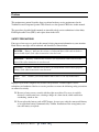
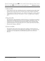
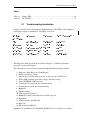
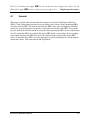
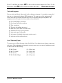
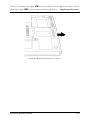
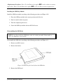
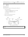
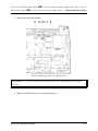
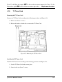
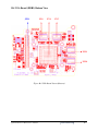
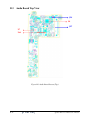
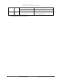
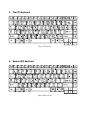
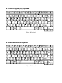
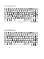
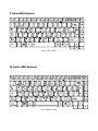
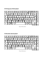
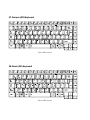
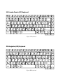
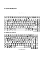
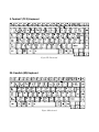
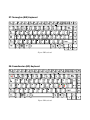
Figure 1-1A show the computer and its system unit configuration.
Figure 1-1A
Qosmio F50 Maintenance Manual
ID Parts Description Placement Part A
1-8
Error! Use the Home tab to apply 2 to the text that you want to appear here. Error! Use the
Home tab to apply 2 to the text that you want to appear here.
Qosmio F50 Maintenance Manual
1 Hardware Overview
1-9
1 Hardware Overview
Error! Use the Home tab to apply 2 to the text that you want to
appear here. Error! Use the Home tab to apply 2 to the text that you want to appear here.
The system unit of the computer consists of the following components:
Processor (BTO)
The computer is equipped with one of the following Intel® processors.
Intel® Dual CoreTM 2 Duo Processor
Memory (BTO)
The computer has two SODIMMs slot comes standard with 512MB/1GB/2GB/4GB,
accepting BTO for your memory requirements. It can incorporate up to 8 GB of main
memory. It supports DDR2 at 667/800MHz.
BIOS ROM (EEPROM)
The system BIOS and Keyboard BIOS share one single 2048KB flash ROM. The flash
utility can be used to program both system and keyboard BIOS at the same time. There is
one EEPROM that is used to store many important system and user data in the notebook.
The size of the EEPROM is 2K bytes.
System Controllers
Advanced Power Management 1.2 support
ACPI2.0 b and PC2001 compliant
Support SMBus specification V2.0
Hot keys for system control
Audio volume output control
External LED control
Battery scope report and control
Sticky key support
Power switch control
Two host interface channels support
Supports three independent devices
Internal Keyboard country selection
Wireless LAN on/off button
Qosmio F50 Maintenance Manual
1-10
Error! Use the Home tab to apply 2 to the text that you want to appear here. Error! Use the
Home tab to apply 2 to the text that you want to appear here.
1 Hardware Overview
Graphics Controller
Intel GM45 as integrated graphics solution
Following External Graphic solution with Intel PM45
− NB9E-GS with GDDR3 (512MB)
− NB9P-GS with DDR2 (512MB)
− NB9M-GE with DDR2 (256MB)
HDMI 1.3-CEC Support
DVI-D supported by conversion cable from HDMI
Express Card Controller
Support USB/PCI Express signals
One Express card slot/54
Audio Controller
Realtek Azalia ALC272
One Audio-in port: Mic.-in/Line-in
One Audio-out port: Headphone-out /Line-out
Internal Microphone (with Internal Camera, MIC with echo cancellation)
Volume control: Digital control, rotary type, no mute function
Microsoft inbox audio driver support
Software EQ support
Dolby Sound Room
MAXX audio support by SW solution (BTO by image)
Wireless LAN Controller
Intel 11a/g (Golan), Intel 11bg (Golan), 11a/g/n (Kedron), (TBD)
Intel 802.11a/g (Echo Peak 1x2 & Shirley Peak 1x2)
Intel 802.11a/g/n (Echo Peak 3x3 Shirley Peak 3x3)
Atheros 802.11a/g (XB62L 1x2), b/g (XB63L 1x2), a/b/g/n (XB722x3), a/b/g/n (XB92
2x2)
Realtek 802.11bg (8187B 1X2) (TBD)
Intel WiMAX 802.16e (Echo Peak 3x3)
Qosmio F50 Maintenance Manual
1-11
1 Hardware Overview
Error! Use the Home tab to apply 2 to the text that you want to
appear here. Error! Use the Home tab to apply 2 to the text that you want to appear here.
Normal screw for all model
Qosmio F50 Maintenance Manual
1-12
Error! Use the Home tab to apply 2 to the text that you want to appear here. Error! Use the
Home tab to apply 2 to the text that you want to appear here.
1.2
1 Hardware Overview
2.5-inch HDD
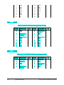
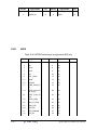
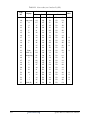
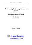
The computer contains an extremely low-profile and lightweight, high-performance HDD. The
HDD incorporates 9.5 mm / 12.5 mm height magnetic disk and mini-Winchester type magnetic
heads. The HDD interface conforms to Serial ATA. Storage capacities supported are 160, 200,
250, 320, 400, and 500 GB.
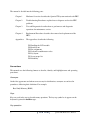
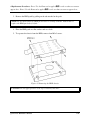
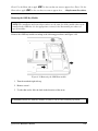
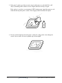
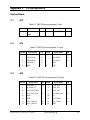
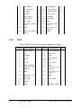
The HDD is shown in Figure 1-2 and some of its specifications are listed in Table 1-1.
Figure 1-2
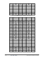
Table 1-1
SATA HDD
HDD Specifications
Specifications
Item
Capacity (GB)
Rotational
Speed (RPM)
Height
User Data
Sectors
Bytes / Sector
160 GB
200 GB
250 GB
4200 RPM
5400 RPM
7200 RPM
4200 RPM
5400 RPM
7200 RPM
4200 RPM
12.5 mm
9.5 mm
9.5 mm
9.5 mm
9.5 mm
9.5 mm
12.5 mm
312,581,808
390,721,968
488,397,168
512
512
512
Qosmio F50 Maintenance Manual
1-13
1 Hardware Overview
Error! Use the Home tab to apply 2 to the text that you want to
appear here. Error! Use the Home tab to apply 2 to the text that you want to appear here.
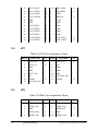
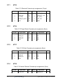
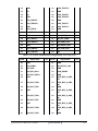
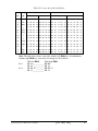
Specifications
Item
Capacity (GB)
300 GB
320 GB
Rotational
Speed (RPM)
4200 RPM
5400 RPM
Height
12.5 mm
9.5 mm
User Data
Sectors
576,072,368
Bytes / Sector
512
Qosmio F50 Maintenance Manual
400 GB
500 GB
7200 RPM
4200 RPM
4200 RPM
9.5 mm
12.5 mm
12.5 mm
625,142,808
781,422,768
976,773,168
512
512
512
1-14
Error! Use the Home tab to apply 2 to the text that you want to appear here. Error! Use the
Home tab to apply 2 to the text that you want to appear here.
1.3
1 Hardware Overview
DVD Super Multi (+-R Double Layer)
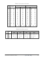
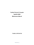
The DVD Super Multi drive accepts 12-cm (4.72-inch) and 8-cm (3.15-inch) discs. At maximum,
the drive can play back a DVD at 8x speed, read CD-ROM at 24x speed, and write CD-R at 24x
speed, CD-RW at 4x speed, US CD-RW at 24x speed, High Speed CD-RW at 10x speed,
DVD-R at 8x speed, DVD-RW at 6x speed, DVD+R at 8x speed, DVD+R (Double Layer) at 4x
speed, DVD-R (Double Layer) at 4x speed, DVD+RW at 8x speed and DVD-RAM at 5x speed.
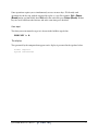
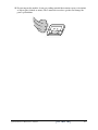
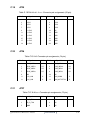
The DVD Super Multi drive is shown in Figure 1-3 and its specifications are listed in Table 1-2.
Figure 1-3
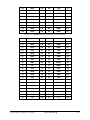
Table 1-2
DVD Super Multi Drive Specifications
Item
Data Transfer Rate
(Mbytes/s)
DVD Super Multi Drive
DVD-ROM Mode
CD-ROM Mode
33.3 (U-DMA transfer mode 2)
16.6 (PIO mode 4, Multiword DMA mode 2)
Access Time (ms)
Average Random Access
130
Data Buffer Size (Mbytes)
2MB
130
DVD:
Formats Supported
DVD-VIDEO, DVD-ROM, DVD-R, DVD-RW, DVD-RAM, DVD+R,
DVD+-R (Double Layer), DVD+RW.
CD:
CD-DA, CD-ROM, CD-R, CD-RW, CD-ROMXA, Photo CD
(Multi-Session), Video CD, CD-Extra (CD+), CD-Text.
Qosmio F50 Maintenance Manual
1-15
1 Hardware Overview
Error! Use the Home tab to apply 2 to the text that you want to
appear here. Error! Use the Home tab to apply 2 to the text that you want to appear here.
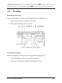
1.4
Power Supply
The power supply unit provides constant voltage 19V for the system board and performs the
following functions:
1. Power input monitor
Checks whether the AC adapter (DC power supply) is connected to the computer.
Checks whether the battery pack is connected to the computer.
Monitors the DC power supply input voltage (AC Adapter output voltage).
2. Power supply's internal control
Turns on and off the battery pack charging power supply.
Issues a charging current instruction to the PWM control IC of the battery pack charging
power supply.
Controls the supply of DC power supply input (AC Adapter output) to the power supply
unit.
Controls the supply of power to the system block (load/logic circuit side).
Controls forced shutdown if the power supply malfunctions.
3. Logic circuit control
Instructs the gate array to enable/disable tuning the power on.
Controls power-on/off operation.
4. Status display
Turns on the Power LED (in White).
Battery indicator (in White or AMBER).
DC-IN indicator (in White color)
5. External interface
Performs communication through the I2C bus (via the internal EC/KBC).
Transfers the power supply operation mode.
Qosmio F50 Maintenance Manual
1-16
Error! Use the Home tab to apply 2 to the text that you want to appear here. Error! Use the
Home tab to apply 2 to the text that you want to appear here.
1 Hardware Overview
6. Output monitor
Monitors the voltage output to the system block (load/logic circuit side).
Monitors the voltage, over voltage, input/output current of the battery pack.
Monitors the internal temperature of the battery pack.
Monitors the supply voltage from the AC adapter.
Qosmio F50 Maintenance Manual
1-17
Error! Use the Home tab to apply 2 to the text that you want to
1 Hardware Overview
appear here. Error! Use the Home tab to apply 2 to the text that you want to appear here.
1.5
Batteries
The computer has the following two types of batteries:
Main Battery Pack
Real Time Clock (RTC) Battery
1.5.1
Main Battery
The main battery pack serves as the computer's main power source when the AC adapter is not
attached. The main battery maintains the state of the computer so that it can resume it.
1.5.2
Battery Charging Control
Battery charging is controlled by EC KB926. When the AC adapter and battery pack are attached
to the computer, the EC KB926 controls the charge on/off state and detects a full charge.
Battery Charge
When the AC adapter is attached, the battery is charged by off-state charge when the system
is powered off or by on-state charge when it is powered on.
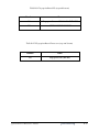
Table 1-3
Quick/Normal Charging Time
State
Charge Time
Off-State Charge
4/8 Cell
About 4 hours max
On-State Charge
4/8 Cell
About 12 hours max
Qosmio F50 Maintenance Manual
1-18
Error! Use the Home tab to apply 2 to the text that you want to appear here. Error! Use the
Home tab to apply 2 to the text that you want to appear here.
1 Hardware Overview
NOTE: The time required for normal charge depends on the power consumption by the
system. Using the fluorescent lamp and frequently accessing the disk consume much power
and lengthen the charge time.
Any of the following cases stops battery charge:
1. The battery becomes fully charged.
2. The AC adapter or battery pack is removed.
3. The battery or AC adapter voltage is abnormal.
Detection of full charge
A full charge is detected only when the battery is being charged by quick or normal charge.
A full charge is detected when either of the following conditions is met:
1. The current in the battery charging circuit drops below the predetermined value.
2. The charging time exceeds the fixed limit.
1.5.3
RTC Battery
The RTC battery provides power to keep the current date, time and other system information in
memory while the computer is turned off.
Qosmio F50 Maintenance Manual
1-19
Chapter 2
Troubleshooting Procedures
2 Troubleshooting Procedures
Chapter 2
Contents
2.1
Troubleshooting Introduction................................................................................... 3
2.2
Troubleshooting Flowchart ……………………………………………………………4
2.3
Power Supply Troubleshooting ..................................................................................9
2.4
Display Troubleshooting..........................................................................................14
2.5
Keyboard Troubleshooting.......................................................................................17
2.6
External USB Devices Troubleshooting ...................................................................19
2.7
TV-tuner Failure Troubleshooting............................................................................21
2.8
TouchPad Troubleshooting ......................................................................................25
2.9
Speaker Troubleshooting .........................................................................................27
2.10
Optical drive troubleshooting ..................................................................................29
2.11
Modem Troubleshooting …………………………………………………………….33
2.12
Express card Troubleshooting ..................................................................................35
2.13
IEEE 1394 Troubleshooting.....................................................................................37
2.14
Wireless LAN Troubleshooting ...............................................................................40
2.15
Camera troubleshooting ...........................................................................................43
2.16
Bluetooth Troubleshooting…………………...…………………………….……….. 45
2.17
7 in 1 card Troubleshooting……………………………………………………..……48
2.18
HDD Troubleshooting………………………………………………………………..50
2.19
CRT failure Troubleshooting ………………………………………………………. 52
2.20
HDMI Troubleshooting ……………………………………………………………...54
2.21
SPDIF Troubleshooting ………….…………………………………………………. 56
2.22
MIC Troubleshooting ………………………………………………………………. 58
2.23
Finger Troubleshooting …………………………………………………………….. 60
2.24
FM tuner Troubleshooting ………………………………………………………….. 62
2.25
E-SATA Troubleshooting ………………………………………….……………….. 65
2.26
Felica Troubleshooting ………………………….………………………………….. 68
2.27
TMA Troubleshooting …………………………….………….…………………….. 70
2.28
UWB Troubleshooting ………..…………………………………………………….. 74
2.29
IR-blaster Troubleshooting ………..…………………………………………….….. 77
2.30
GPS Troubleshooting ……………………………………………………………….. 79
QOSMIO F50- QOSMIO F55- DYNABOOK QOSMIO F50 Series Maintenance Manual
1
2 Troubleshooting Procedures
Figures
Figure 2-1
Troubleshooting flowchart (1/2)..................................................................... 5
Figure 2-1
Troubleshooting flowchart (2/2).................................................................... 6
Figure 2-3
Display troubleshooting process................................................................... 14
Figure 2-4
Keyboard troubleshooting process ............................................................... 17
Figure 2-5
External USB device troubleshooting process .............................................. 19
Figure 2-6
TV-tuner troubleshooting process ................................................................ 21
Figure 2-7
TouchPad troubleshooting process ............................................................... 25
Figure 2-8
Speaker troubleshooting process .................................................................. 27
Figure 2-9
Optical drive troubleshooting process .......................................................... 29
Figure 2-10
Modem troubleshooting process................................................................... 33
Figure 2-11
Express card troubleshooting process........................................................... 35
Figure 2-12
IEEE 1394 troubleshooting process.............................................................. 37
Figure 2-13
Wireless LAN troubleshooting process ........................................................ 40
Figure 2-14
Camera troubleshooting process................................................................... 43
Figure 2-15
Bluetooth troubleshooting process…..……………………………….……….45
Figure 2-16
7 in 1 card troubleshooting process……………………………..…….………48
Figure 2-17
HDD troubleshooting process……………………………….………………..50
Figure 2-18
CRT failure troubleshooting process ………………………………………...52
Figure 2-19
HDMI Troubleshooting process ……………………………………………...54
Figure 2-20
SPDIF troubleshooting process …..…………………………………………..56
Figure 2-21
MIC troubleshooting process ………………………………………………...58
Figure 2-22
Finger printer troubleshooting process ………………………………………60
Figure 2-23
FM tuner Troubleshooting ………………………………………………….. 62
Figure 2-24
E-SATA Troubleshooting ………………………………….……………….. 65
Figure 2-25
Felica Troubleshooting ……..………………….………….………………... 68
Figure 2-26
TMA Troubleshooting ………………………….………….……….…..…... 70
Figure 2-27
UWB Troubleshooting ………..………………………………….…..….….. 74
Figure 2-28
IR-blaster Troubleshooting ……..………………………………...……..….. 77
Figure 2-29
GPS Troubleshooting ………...……………………………………………... 79
QOSMIO F50- QOSMIO F55- DYNABOOK QOSMIO F50 Series Maintenance Manual
2
2 Troubleshooting Procedures
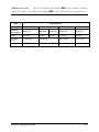
Tables
Table 2-1
Battery LED....................................................................................................10
Table 2-2
DC-IN LED ....................................................................................................11
2.1
Troubleshooting Introduction
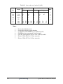
Chapter 2 describes how to determine if a Field Replaceable Unit (FRU) in the computer is
causing the computer to malfunction. The FRUs covered are:
+#
*
$
!
0(
/ "% #
!" #
#
& '. "# !
$ !
'''
1 2)3
$
! !%
,/
-
4
& '(
))
"
)
1 $ -5( !
The Diagnostics Disk operations are described in Chapter 3. Detailed replacement
procedures are given in Chapter 4.
The following tools are necessary for implementing the troubleshooting procedures:
1. Diagnostics Disk (Repair and Sound Repair)
2. Phillips screwdriver (2 mm)
3. 6mm nut driver (for the helix screw nuts on the rear ports for CPU door)
4. 2DD or 2HD formatted work disk for floppy disk drive testing
5. Sycard (EXPRESS CARD test card)
6. Cleaning kit for floppy disk drive troubleshooting
7. Cleaning kit for optical drive troubleshooting
8. Multimeter
9. External monitor
10. USB compatible keyboard
11. Multimedia sound system with line-in and line-out ports
12. Headphones
13. USB test module and USB cable
14. Music CD
15. MIC module and MIC line
QOSMIO F50- QOSMIO F55- DYNABOOK QOSMIO F50 Series Maintenance Manual
3
2 Troubleshooting Procedures
16. SPDIF line
17. Finger print module
18. TV tuner signal generator
19. FM tuner signal generator
20. E-SATA HDD
21. Felica card
22. UWB signal generator
23. Remote controller.
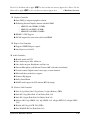
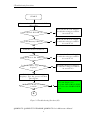
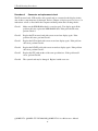
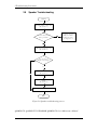
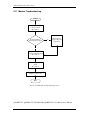
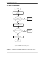
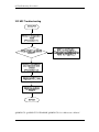
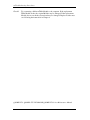
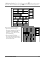
2.2
Troubleshooting Flowchart
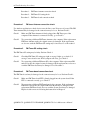
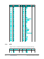
If you know the location of the malfunction, turn directly to the appropriate section of this
chapter. If the problem is unspecified, use the flowchart in Figure 2-1 as a guide for
determining which troubleshooting procedures to execute. Before performing any
troubleshooting procedures, verify the following:
Ask the user if a password is registered, if it is, ask him or her to enter the password.
Verify with the customer that Toshiba Windows Vista is installed on the hard disk.
Operating systems that were not preinstalled by Toshiba can cause the computer to
malfunction.
Make sure all optional equipment is removed from the computer.
Make sure the floppy disk drive, if installed, is empty. If no FDD module is installed,
you should use an external FDD to run the diagnostics tests
QOSMIO F50- QOSMIO F55- DYNABOOK QOSMIO F50 Series Maintenance Manual
4
2 Troubleshooting Procedures
STA RT
C o n n e c t th e A C a d a p te r to th e D C IN s o c k e t
<=
Is th e D C -IN L E D o n ?
P e rfo rm th e P o w e r S u p p ly
T ro u b le s h o o tin g p ro c e d u re s
in s e c tio n 2 .3
6 78
<=
Is th e B a tte ry L E D o n ?
6 78
P e rfo rm th e P o w e r S u p p ly
T ro u b le s h o o tin g p ro c e d u re s
in s e c tio n 2 .3
T u rn th e P o w e r s w itc h o n
9 :;
Is th e P o w e r O n L E D o n ?
<=
9 :;
Is th e " T o s h ib a " lo g o m e s s a g e
d is p la y ?
<=
9 :;
P e rfo rm th e P o w e r S u p p ly
T ro u b le s h o o tin g p ro c e d u re s
in s e c tio n 2 .3
P e rfo rm th e P o w e r S u p p ly
T ro u b le s h o o tin g p ro c e d u re s
in s e c tio n 2 .3
If th e " p a s s w o rd " m e s s a g e
d is p la y s , ty p e th e p a s s w o rd , th e n
p re s s E n te r.
Is T o s h ib a W in d o w s b e in g
lo a d e d ?
9 :;
<=
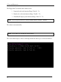
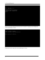
P e rfo rm d ia g n o s tic s
p ro g ra m . R u n C M 1 6 5 .E X E
a n d s e le c t th e H A R D D IS K
ite m .
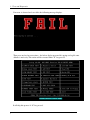
A
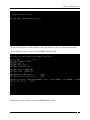
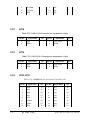
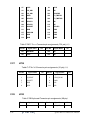
Figure 2-1 Troubleshooting flowchart (1/2)
QOSMIO F50- QOSMIO F55- DYNABOOK QOSMIO F50 Series Maintenance Manual
5
2 Troubleshooting Procedures
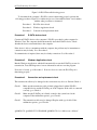
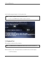
A
Does typed characters appear correctly?
AB
Perform the Keyboard
Troubleshooting procedures
in section 2.6
AB
Perform the FDD
Troubleshooting procedures
in section 2.5
>?@
Insert the diagnostics disk into the FDD.
Then run the diagnostics test program.
>?@
Is the diagnostics test loaded?
>?@
Allow each test to perform
automatically
>?@
Is an error detected by any of the
diagnostics tests?
After confirming which
diagnostics test has detected
an error, perform the
appropriate procedure as
outlined below.
AB
System is normal
End
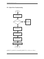
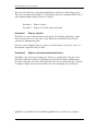
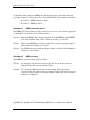
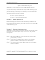
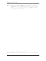
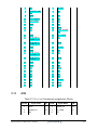
Figure 2-1 Troubleshooting flowchart (2/2)
QOSMIO F50- QOSMIO F55- DYNABOOK QOSMIO F50 Series Maintenance Manual
6
2 Troubleshooting Procedures
If the diagnostics program cannot detect an error, the problem may be intermittent. The test
program should be executed several times to isolate the problem. When a problem has been
located, perform the appropriate troubleshooting procedures as follows:
1. If an error is detected by the battery test, perform the Power Supply Troubleshooting
procedures in Section 2.2
2. If an error is detected by the display test, perform the Display Troubleshooting
procedures in Section 2.3
3. If an error is detected by the keyboard test, perform the Keyboard Troubleshooting
procedures in Section 2.4
4. If an error is detected by the TouchPad test, perform the TouchPad Troubleshooting
procedures in Section 2.7
5. If an error is detected by the audio test, perform the Speaker Troubleshooting
procedures in Section 2.8 and the Optical Drive Troubleshooting Procedures in
Section 2.9
6. If an error is detected by the fingerprint test, perform the fingerprinter troubleshooting
Procedures in Section 2.22
QOSMIO F50- QOSMIO F55- DYNABOOK QOSMIO F50 Series Maintenance Manual
7
2 Troubleshooting Procedures
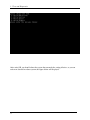
Other problems that are not covered by the diagnostics program may be discovered by a
user.
1. If an error is detected when using an external USB device, perform the External USB
Devices Troubleshooting procedures in Section 2.5
2. If an error is detected when using the TV-out connection, perform the TV-Out Failure
Troubleshooting procedures in Section 2.6
3. If an error is detected when using the speakers, perform the Speaker Troubleshooting
procedures in Section 2.8
4. If an error is detected when using the modem, perform the Modem Troubleshooting
procedures in Section 2.10
5. If an error is detected when using the EXPRESS CARD unit, perform the EXPRESS
CARD Troubleshooting procedures in Section 2.11
6. If an error is detected when using the IEEE1394 device, perform the IEEE1394 device
Troubleshooting procedures in Section 2.12
7. If an error is detected when using the Wireless LAN, perform the Wireless LAN
Troubleshooting procedures in Section 2.13
8. If an error is detected when using the Bluetooth, perform the Bluetooth
Troubleshooting procedures in Section 2.15
9. If an error is detected when using the HDMI TV, perform the HDMI TV
troubleshooting procedures in Section 2.19.
10. If an error is detected when using the MIC, perform the MIC troubleshooting
procedures in Section 2.21
QOSMIO F50- QOSMIO F55- DYNABOOK QOSMIO F50 Series Maintenance Manual
8
2 Troubleshooting Procedures
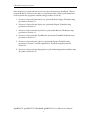
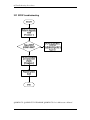
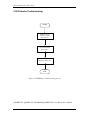
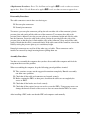
2.3
Power Supply Troubleshooting
ST A R T
C heck Po w er Sup ply Status
(P roced ure 1 )
CD
A re the D C -IN and
B attery L E D s lit?
R ep lace ad ap to r / battery
(P ro ced ure 2)
EFG
C heck po wer sup ply
connections
(P roced ure 3 )
EFG
C an you turn the
co mp uter o n?
R un diagno stic pro gram
(P ro ced ure 4)
CD
CD
A re the internal po w er
connections secure?
P erform internal co nnectio n
check
(P ro ced ure 5)
EFG
R eplace system bo ard
END
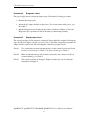
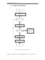
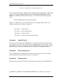
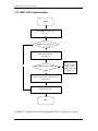
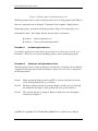
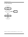
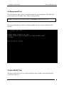
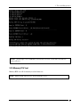
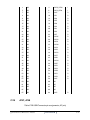
Figure 2-2 Power Supply Troubleshooting Process
The power supply controls many functions and components. To determine if the power
supply is functioning properly, start with Procedure 1 and continue with the other Procedures
QOSMIO F50- QOSMIO F55- DYNABOOK QOSMIO F50 Series Maintenance Manual
9
2 Troubleshooting Procedures
as instructed. The flowchart in Figure 2-2 gives a summary of the process. The procedures
described in this section are:
Procedure 1: Power status check
Procedure 2: Adaptor / battery replacement
Procedure 3: Power supply connection check
Procedure 4: Diagnostic check
Procedure 5: Internal connection check
Procedure 1
Power Status Check
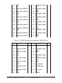
The following LEDS indicate the power supply status:
Battery LED
DC-IN LED
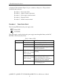
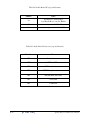
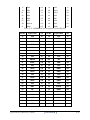
The power supply controller displays the power supply status through the Battery and the DCIN LEDS as listed in the tables below.
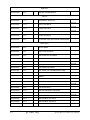
Table 2-1 Battery LED
Battery State
LED colors
Definition
Charging
Amber, solid on
Battery charging with AC.
Blue, solid on
Battery fully charged by AC
Blue color off
Battery abnormal stop charging with AC
(Bad cell/ Overheated)
Amber, blinking
Battery within low state: 12 minutes
remaining
Discharging
(LED on for 1 second
every 4 seconds)
Battery within critical low state: 3
minutes remaining. The system is
(LED on for 1 second
protected and cannot be re-powered on
every 2 seconds)
without the AC power connected.
Amber, blinking
Amber color off
Battery not in low or critical low state;
It’s in discharging state
QOSMIO F50- QOSMIO F55- DYNABOOK QOSMIO F50 Series Maintenance Manual
10
2 Troubleshooting Procedures
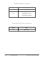
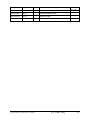
Table 2-2 DC-IN LED
AC-IN LED
Power supply status
Solid on
AC power exists (LED is solid Blue).
Off
No AC power exists.
To check the power supply status, install a battery pack and connect an AC adaptor to the
DC-IN port on the computer and to a power supply.
If the DC-IN LED or Battery LED is not lit, go to Procedure 2.
Procedure 2
Adaptor / battery replacement
A faulty adaptor may not supply power or may not charge the battery. Perform Check 1.
Check 1
Connect a new AC adaptor. If the problem is not resolved, go to Check 2.
Check 2
Insert a new battery. If the problem is still not resolved, go to Procedure 3.
QOSMIO F50- QOSMIO F55- DYNABOOK QOSMIO F50 Series Maintenance Manual
11
2 Troubleshooting Procedures
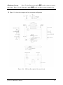
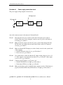
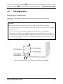
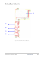
Procedure 3
Power supply connection check
The power supply wiring diagram is shown below:
ACadaptor cord
ACpower cord
AC
adaptor
System
board
Battery
Any of the connectors may be disconnected. Perform Check 1.
Check 1
Disconnect the AC power cord from wall outlet. Check the power cable for
breaks. If the power cord is damaged, connect a new AC power cord. If there is
no damage, go to Check 2.
Check 2
Make sure the AC adaptor cord and AC power cord are firmly plugged into the
DC-IN socket, AC adaptor inlet and wall outlet. If these cables are connected
correctly, go to Check 3.
Check 3
Make sure that the DC-IN input port socket is firmly secured to the system board
of the computer.
• If the DC-IN input socket is loose, go to Procedure 5.
• If it is not loose, go to Check 4.
Check 4
Use a multi-meter to make sure that the AC adaptor output voltage is close to 19
V. If the output is several percent lower than 19 V, go to Check 5. If the output
is close to 19 V, go to Check 6.
Check 5
Connect a new AC adaptor or AC power cord.
• If the DC-IN LED does not light, go to Procedure 4.
• If the battery LED does not light, go to Check 6.
Check 6
Make sure the battery pack is installed in the computer correctly. If the battery is
properly installed and the battery LED still does not light, go to Procedure 4.
QOSMIO F50- QOSMIO F55- DYNABOOK QOSMIO F50 Series Maintenance Manual
12
2 Troubleshooting Procedures
Procedure 4
Diagnostic check
The power supply may not charge the battery pack. Perform the following procedures:
1. Reinstall the battery pack.
2. Attach the AC adaptor and turn on the power. If you cannot turn on the power, go to
Procedure 5.
3. Run the Diagnostic test following the procedures described in Chapter 3, Tests and
Diagnostics. If no problem is detected, the battery is functioning normally.
Procedure 5
Replacement check
The system board may be disconnected or damaged. Disassemble the computer following the
steps described in Chapter 4, Replacement Procedures. Check the connection between the AC
adaptor and the system board. After checking the connection, perform Check 1:
Check 1
Use a multi-meter to make sure that the fuses on the system board are not blown.
If a fuse is not blown, go to Check 2. If a fuse is blown, go to Check 3.
Check 2
Make sure that the battery cable is firmly connected to the system board. If it is
connected firmly, go to Check 3.
Check 3
The system board may be damaged. Replace it with a new one following the
instructions in Chapter 4.
QOSMIO F50- QOSMIO F55- DYNABOOK QOSMIO F50 Series Maintenance Manual
13
2 Troubleshooting Procedures
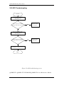
2.4
Display Troubleshooting
STA RT
P e r fo r m e x te r n a l d is p la y c h e c k
(P ro c ed u re 1 )
D o e s th e e x te rn a l
d is p la y f u n c tio n o k ?
HI
P e rf o r m d ia g n o s tic c h e c k
(P ro c ed u re 2 )
J KL
W a s a d is p la y
p r o b le m d e te c te d ?
HI
D is p la y is n o t
fa u lty . C o n tin u e
tr o u b le s h o o tin g r e f e r to F ig u r e 2 .1
J KL
P e r f o r m c o n n e c to r a n d
r e p la c e m e n t c h e c k
(P ro c ed u re 3 )
R e p la c e s y s te m b o a rd
EN D
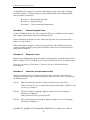
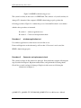
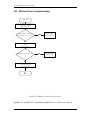
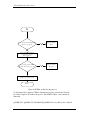
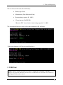
Figure 2-3 Display troubleshooting process
QOSMIO F50- QOSMIO F55- DYNABOOK QOSMIO F50 Series Maintenance Manual
14
2 Troubleshooting Procedures
This section describes how to determine if the computer’s display is functioning properly.
The process is outlined in Figure 2-3. Start with Procedure 1 and continue with the other
procedures as instructed.
Procedure 1: External display check
Procedure 2: Diagnostic check
Procedure 3: Connector and replacement check
Procedure 1
External display check
Connect an external display to the computer’s external monitor port, and then boot the
computer. The computer automatically detects the external display.
If the external display works correctly, the internal LCD may be damaged. Go to Procedure 3.
If the external monitor appears to have the same problem as the internal monitor, the system
board may be damaged. Go to Procedure 2.
Procedure 2
Diagnostic check
The Display Test program is stored on the computer’s Diagnostics disk. This program checks
the display controller on the system board. Insert the Diagnostics disk in the computer’s
floppy disk drive, turn on the computer and run the test. Refer to Chapter 3, Tests and
Diagnostics for details.
If an error is detected, go to Procedure 3. If an error is not detected, the display is functioning
properly.
QOSMIO F50- QOSMIO F55- DYNABOOK QOSMIO F50 Series Maintenance Manual
15
2 Troubleshooting Procedures
Procedure 3
Connector and replacement check
The FL inverter board, LCD module, and system board are connected to the display circuits.
Any of these components may be damaged. Refer to Chapter 4, Replacement Procedures, for
instructions on how to disassemble the computer and then perform the following checks:
Check 1
Make sure the DDR RAM module is seated properly. Test display again. If the
problem still exits, replace the DDR RAM module. If the problem still exists,
perform Check 2.
Check 2
Replace the FL inverter board with a new one and test display again. If the
problem still exists, perform Check 3.
Check 3
Replace the LCD module with a new one and test display again. If the problem
still exists, perform Check 4.
Check 4
Replace the LCD/FL cable with a new one and test display again. If the problem
still exists, perform Check 5.
Check 5
Replace the CPU with another of the same specifications. If the problem still
exists, perform Check 6.
Check 6
The system board may be damaged. Replace it with a new one.
QOSMIO F50- QOSMIO F55- DYNABOOK QOSMIO F50 Series Maintenance Manual
16
2 Troubleshooting Procedures
2.5
Keyboard Troubleshooting
STA RT
P e rfo rm e x te rn a l k e y b o a r d c h e c k
(P ro c e d u re 1 )
D o e s th e e x te rn a l
k e y b o a rd fu n c tio n o k ?
M NO
P e r fo rm d ia g n o s tic c h e c k
( P ro c e d u re 2 )
RS
W a s a k e y b o a rd
p ro b le m d e te c te d ?
PQ
K e y b o a r d is n o t
fa u lty . C o n tin u e
tro u b le s h o o tin g -re fe r
to F ig u re 2 .1
M NO
P e rfo rm c o n n e c to r a n d
re p la c e m e n t c h e c k
( P ro c e d u re 3 )
R e p la c e s y s te m b o a rd
END
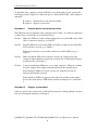
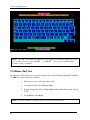
Figure 2-4 Keyboard troubleshooting process
QOSMIO F50- QOSMIO F55- DYNABOOK QOSMIO F50 Series Maintenance Manual
17
2 Troubleshooting Procedures
To determine if the computer’s keyboard is functioning properly, perform the following
procedures. Figure 2-5 outlines the process. Start with Procedure 1 and continue with the
other procedures as instructed.
Procedure 1: External keyboard check
Procedure 2: Diagnostic check
Procedure 3: Connector and replacement check
Procedure 1
External keyboard check
Connect a USB keyboard to one of the computer’s USB ports, and then boot the computer.
The computer automatically detects the external keyboard.
If the external keyboard works correctly, the internal keyboard or its connections may be
faulty. Go to Procedure 2.
If the external keyboard appears to have the same problem as the internal keyboard, the
system board may be having some problem. Replace it with a new one and following the
instructions in Chapter 4.
Procedure 2
Diagnostic check
Run the test and Diagnostics Program, which will automatically execute the Keyboard Test.
Refer to Chapter 3, Tests and Diagnostics for more information on how to run the program.
If an error is located, go to Procedure 3. If an error does not occur, the keyboard is
functioning ok.
Procedure 3
Connector and replacement check
The keyboard and/or system board may be disconnected or damaged. Disassemble the
computer following the steps described in Chapter 4, Replacement Procedures and perform
the following checks.
Check 1
Make sure the keyboard cable is firmly connected to the system board.
If the connection is loose, reconnect firmly and repeat Procedure 2. If there is still
an error, go to Check 2.
Check 2
The keyboard may be damaged. Replace it with a new one following the
instructions in Chapter 4.
If the problem still exists, perform Check 3.
Check 3
The system board may be damaged. Replace it with a new one following the
instructions in Chapter 4.
QOSMIO F50- QOSMIO F55- DYNABOOK QOSMIO F50 Series Maintenance Manual
18
2 Troubleshooting Procedures
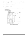
2.6 External USB Devices Troubleshooting
START
P e rf o rm e x te r n a l d e v ic e a n d
c o n n e c tio n c h e c k
( P ro c e d u r e 1 )
C h eck U SB
p o rt
c o n n e c tio n
V WX
D o e s th e d e v ic e f u n c tio n
w h e n c o n n e c te d to a
d if f e re n t U S B p o rt?
TU
D o e s a n a lte r n a tiv e U S B
d e v ic e f u n c tio n c o r r e c tly ?
V WX
O r ig in a l U S B
d e v ic e is f a u lty
TU
R e p la c e s y s te m b o a r d
( P ro c e d u r e 2 )
END
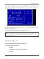
Figure 2-5 External USB device troubleshooting process
QOSMIO F50- QOSMIO F55- DYNABOOK QOSMIO F50 Series Maintenance Manual
19
2 Troubleshooting Procedures
To determine if the computer’s external USB devices are functioning properly, perform the
following procedures. Figure 2-6 outlines the process. Start with Procedure 1 and continue as
instructed.
Procedure 1: External device and connection check
Procedure 2: Replace system board
Procedure 1
External device and connection check
The USB device may be damaged or the connection may be faulty. Use windows application
to check device can work fine or not, Perform Check 1.
Check 1
Make sure USB device cable is firmly plugged into one of the USB sockets. If the
cable is connected correctly, go to Check 2.
Check 2
Plug the USB device into another USB socket (there are three in all). If the USB
device still does not work, go to Check 4.
If the device functions correctly when connected to another USB port, go to
Check 3.
Check 3
Make sure that the USB socket is firmly secured to the system board of the
computer. If the malfunction remains, the system board or USB small board may
be damaged. Go to Procedure 2.
Check 4
Connect an alternative USB device to one of the computer’s USB ports, and then
boot the computer. The computer automatically detects the external device.
If the alternative USB device works correctly, the original device may be
damaged and should be replaced.
If the alternative USB device appears to have the same problem as the original
device, the system board or USB small board may be damaged. Go to Procedure
2.
Procedure 2
Replace system board
If the error persists, the system board or USB small board may be damaged. Replace it with a
new one following the instructions in Chapter 4.
QOSMIO F50- QOSMIO F55- DYNABOOK QOSMIO F50 Series Maintenance Manual
20
2 Troubleshooting Procedures
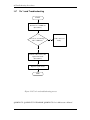
2.7
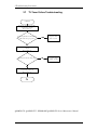
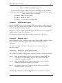
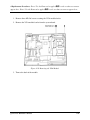
TV-Tuner Failure Troubleshooting
START
P e r f o rm T V T u n e r C a b le
c o n n e c tio n c h e c k
(P r o c e d u re 1 )
D o e s re p la c e m e n t T V T u n e r
c a b le f u n c tio n p ro p e r ly ?
Y Z[
R e p la c e T V
T u n e r c a b le
\]
P e r f o rm T V T u n e r S G s e ttin g
check
(P r o c e d u re 2 )
T V T u n e r fu n c tio n in g o k ?
Y Z[
U s e th e rig h t
s e ttin g o n S G
\]
P e r fo r m T V T u n e r A n te n n a
C o n n e c tio n c h e c k
(P r o c e d u re 3 )
A
QOSMIO F50- QOSMIO F55 - DYNABOOK QOSMIO F50 Series Maintenance Manual
21
2 Troubleshooting Procedures
Figure 2-6 TV-out troubleshooting process
A
D o e s r e p la c e m e n t T V T u n e r
A n te n n a f u n c tio n p r o p e r ly ?
^ _`
R e p la c e T V
T u n e r A n te n n a
ab
P e r fo rm T V T u n e r M o d u le
c o n n e c tio n c h e c k
(P r o c e d u re 4 )
D o e s r e p la c e m e n t T V T u n e r
M o d u le f u n c tio n p ro p e r ly ?
^ _`
R e p la c e T V
T u n e r M o d u le
R e p la c e s y s te m b o a r d
END
QOSMIO F50- QOSMIO F55 - DYNABOOK QOSMIO F50 Series Maintenance Manual
22
2 Troubleshooting Procedures
To determine if the computer’s TV Tuner port is functioning properly, perform the following
procedures. Figure 2-7 outlines the process. Start with Procedure 1 and continue as instructed.
Procedure 1: TV Tuner cable connection check
Procedure 2: TV Tuner SG setting check
Procedure 3: TV Tuner Antenna connection check
Procedure 4: TV Tuner Module connection check
Procedure 1
TV tuner Cable connection check
The TV Tuner cable may be damaged or the connections may be loose. Use windows
application to check device can work fine or not. If an error is located, Perform Check 1:
Check 1
Make sure TV Tuner cable is firmly plugged into both the TV Tuner set and the
TV Tuner port of the computer. If the cable is connected correctly, go to Check 2.
Check 2
Make sure the TV Tuner port is firmly secured to the system board of the
computer. If the malfunction remains, go to Check 3.
Check 3
The TV Tuner cable may be damaged. Replace with a good cable. If the
malfunction remains, go to Procedure 2.
Procedure 2
TV Tuner SG setting check
The TV Tuner SG setting may be faulty. Perform Check 1:
Check 1
Check the TV Tuner Setting was right or wrong, if right; go to check 2, if wrong.
Correct it and re-test. If fail symptom still exist, go to Procedure
Check 2
Try connecting a different TV tuner SG to the computer. If the replacement TV
tuner SG works, the original set may be damaged. If the replacement set does not
work the TV tuner Antenna may be damaged. Go to Procedure 3.
Procedure 3
TV tuner Antenna connection check
The TV Tuner Antenna may be damaged or the connections may be loose. Perform Check 1:
QOSMIO F50- QOSMIO F55 - DYNABOOK QOSMIO F50 Series Maintenance Manual
23
2 Troubleshooting Procedures
Check 1
Make sure TV Tuner Antenna is firmly plugged into both the TV Tuner Module.
If the antenna is connected correctly, go to Check 2.
Check 2
Try connecting a different TV tuner Antenna to the computer. If the replacement
TV tuner Antenna works, the original Antenna may be damaged. If the
replacement Antenna does not work the TV tuner Module may be damaged. Go to
Procedure 4.
Procedure 4
TV Tuner Module Connection check
The TV Tuner Module connect may be faulty. Perform Check 1:
Check 1
Check the TV Tuner Module is firmly plugged into system board, if connection
was correctly, go to check 2.
Check 2
Try connecting a different TV tuner Module to the computer. If the replacement
TV tuner Module works, the original Module may be damaged. If the replacement
Module does not work the system board may be damaged. Replace it with a new
one following the instructions in Chapter 4.
QOSMIO F50- QOSMIO F55 - DYNABOOK QOSMIO F50 Series Maintenance Manual
24
2 Troubleshooting Procedures
2.8
TouchPad Troubleshooting
START
TouchPad connection
check (Procedure 1)
TouchPad replacement
check (Procedure 2)
Replace system board
END
Figure 2-7 Touchpad troubleshooting process
QOSMIO F50- QOSMIO F55 - DYNABOOK QOSMIO F50 Series Maintenance Manual
25
2 Troubleshooting Procedures
To determine if the computer’s built-in TouchPad is functioning properly, perform the
following procedures. Figure 2-9 outlines the process. Start with Procedure 1 and continue as
instructed.
Procedure 1: TouchPad connection check
Procedure 2: TouchPad replacement check
Procedure 1
TouchPad connection check
The TouchPad is connected via the TouchPad FPC to the system board. Make sure the
TouchPad FPC cable is firmly connected to the TouchPad and system board. Refer to Chapter
4, Replacement Procedures, for instructions on how to disassemble the computer and then
perform the following checks.
If any of the connections are loose, reconnect firmly. If any of the connections is damaged, or
there is still an error, go to Procedure 2.
Procedure 2
TouchPad replacement check
The TouchPad unit or FPC may be defective or damaged. Replace each with a new one
following the steps in Chapter 4. If the FDD is still not functioning properly, replace the
system board with a new one following the steps in Chapter 4.
QOSMIO F50- QOSMIO F55 - DYNABOOK QOSMIO F50 Series Maintenance Manual
26
2 Troubleshooting Procedures
2.9
Speaker Troubleshooting
ST A RT
P e rfo r m a u d io s o u r c e te s t
( P ro c e d u r e 1 )
D o a ll s o u r c e s h a v e
s a m e p r o b le m ?
cd
S p eak ers are no t
fa u lty . C o n tin u e
tr o u b le s h o o tin g s e e F ig u r e 2 -1
e fg
P e r fo r m e a r p h o n e te s t
( P ro c e d u r e 2 )
D o earp ho n es
fu n c tio n c o r r e c tly ?
Y es
No
P e r fo r m c o n n e c tio n c h e c k
( P ro c e d u r e 3 )
P e r fo r m r e p la c e m e n t
check
( P ro c e d u r e 4 )
R e p la c e s y s te m b o a r d
END
Figure 2-8 Speaker troubleshooting process
QOSMIO F50- QOSMIO F55- DYNABOOK QOSMIO F50 Series Maintenance Manual
27
2 Troubleshooting Procedures
To determine if the computer’s built-in speakers are functioning properly, perform the
following procedures. Figure 2-10 outlines the process. First adjust the speaker volume to an
appropriate level. Start with Procedure 1 and continue as instructed.
Procedure 1: Audio source test
Procedure 2: Earphone test
Procedure 3: Connection check
Procedure 4: Replacement check
Procedure 1
Audio source test
Try different audio sources (e.g. an audio CD and digital music file) to determine whether the
fault is in the speaker system or not. If not all sources have sound problem, the problem is in
the source devices. If all have the same problem, continue with Procedure 2.
Procedure 2
Earphone test
Connect a set if earphones or external speakers. If these function correctly, go to Procedure 3.
If they do not function correctly, the system board may be defective or damaged. Replace it
with a new one.
Procedure 3
Connection check
Disassemble the computer following the steps described in Chapter 4, Replacement
Procedures and make sure the speaker cable is firmly connected to the audio board. If the
stereo speakers are still not functioning properly, go to Procedure 4.
Procedure 4
Replacement check
If the stereo speakers don't sound properly, the stereo speakers may be defective or damaged.
Replace them with new ones. If the stereo speakers still do not work properly, try replacing in
turn the audio board and system board.
QOSMIO F50- QOSMIO F55- DYNABOOK QOSMIO F50 Series Maintenance Manual
28
2 Troubleshooting Procedures
2.10 Optical Drive Troubleshooting
START
Perform audio CD check
(Procedure 1)
Audio CD functions ok?
No
Perform drivecleaning check
(Procedure 2)
Yes
Perform software check
(Procedure 3)
Perform diagnostic test
(Procedure 4)
Perform connection and
replacement check
(Procedure 5)
Replace system board
END
QOSMIO F50- QOSMIO F55- DYNABOOK QOSMIO F50 Series Maintenance Manual
29
2 Troubleshooting Procedures
Figure 2-9 Optical drive troubleshooting process
This section describes how to determine if the computer’s internal optical drive is functioning
properly. The Satellite P200D / P205D Satellite Pro P200D EQUIUM P200D SATEGO
P200D Series Maintenance Manual module bays can accommodate the following optical
drives:
DVD SuperMulti supporting +-R Double Rayer
Figure 2-11 outlines the process. Perform the steps below starting with Procedure 1 and
continue with the other procedures as required.
Procedure 1: Audio CD test
Procedure 2: Drive cleaning check
Procedure 3: Software check
Procedure 4: Connection and replacement check
Procedure 1
Audio CD check
First, insert an audio CD into the CD/DVD drive. Use windows application to check device
can work fine or not. If it works, the problem is not with the drive. Go to Procedure 3. If the
audio CD does not work, go to Procedure 2. If the CD/DVD LED on the front panel does not
light when the disc is played and the drive gives no response, go straight to Procedure 3.
Procedure 2
Drive cleaning check
Insert a CD/DVD drive-cleaning disk into the drive clean according to the drive-cleaning
product instructions. If the problem persists, go to Procedure 3.
Procedure 3
Software check
Ensure that the appropriate driver has been installed on the computer for the CD/DVD drive.
QOSMIO F50- QOSMIO F55- DYNABOOK QOSMIO F50 Series Maintenance Manual
30
2 Troubleshooting Procedures
Procedure 4
Connection check and replacement check
The optical drive connects to the system board. The drive may be disconnected, or the drive
or system board may be damaged. Disassemble the computer following the steps described in
Chapter 4, Replacement Procedures, and perform the following checks:
Check 1
Make sure the drive is firmly connected to the system board. If the connection is
good and there is still an error, go to Check 2.
Check 2
The drive or drive cable may be defective or damaged. Replace each with a new
one following the steps in Chapter 4, Replacement Procedures. If the drive is still
not functioning properly, perform Check 3.
Check 3
The system board may be damaged. Replace it with new one following the
instructions in Chapter 4, Replacement Procedures.
QOSMIO F50- QOSMIO F55- DYNABOOK QOSMIO F50 Series Maintenance Manual
31
32
Troubleshooting Procedures
2.11 Modem Troubleshooting
START
Perform telephone line
connection check
(Procedure 1)
Computer unable to
detect telephone signal?
Yes
Check / replace
telephone line and
connections
No
Perform connection check
(Procedure 2)
Perform replacement
check
(Procedure 3)
Replace system board
END
Figure 2-10 Modem troubleshooting process
QOSMIO F50- QOSMIO F55- DYNABOOK QOSMIO F50 Series Maintenance Manual
32
33
Troubleshooting Procedures
This section describes how to determine if the computer's modem is functioning properly.
Figure 2-12 outlines the process. Perform the steps below starting with Procedure 1 and
continuing with the other procedures as required.
Procedure 1: Telephone line connection check
Procedure 2: Modem card connection check
Procedure 3: Modem card replacement check
Procedure 1
Telephone line connection check
The telephone cable may be damaged or the connections may be loose. Use windows
application to check device can work fine or not. Attempt to connect the computer to a
network through using the modem. If the modem does not function at all, go to Procedure 3.
If the attempt fails because the computer detects no telephone signal, the fault may be in the
telephone cable, the wall socket or the modem port. Perform Check 1:
Check 1
Make sure telephone cable is firmly plugged into both the telephone wall socket
and the modem port of the computer. If the cable is connected correctly, go to
Check 2.
Check 2
Make sure the modem port is firmly secured to the system board of the computer.
If the malfunction remains, go to Check 3.
Check 3
The telephone cable may be damaged. Replace with a good cable. If the
malfunction remains, go to Procedure 2.
Procedure 2
Modem card connection check
Disassemble the computer following the steps described in Chapter 4, Replacement
Procedures and ensure that the modem card is well connected to the system board. If the
problem persists, perform Procedure 3.
Procedure 3
Modem replacement check
The modem card or RJ-11 jack may be faulty. Try replacing them. If the problem persists, the
system board may be defective or damaged. Replace the System Board with a new one
following the steps in Chapter 4, Replacement Procedures.
QOSMIO F50- QOSMIO F55- DYNABOOK QOSMIO F50 Series Maintenance Manual
33
34
Troubleshooting Procedures
2.12 Express card Troubleshooting
START
P e rfo rm E x p re ss c a rd te st
(P ro c e d u re 1 )
D o e rro rs o c c u r d u rin g
E x p re ss c a rd te st?
No
E x p re ss c a rd u n it
is n o t fa u lty .
Y es
P e rfo rm E x p re ss c a rd so c k e t
re p la c e m e n t c h e c k
(P ro c e d u re 2 )
R e p la ce sy ste m b o a rd
END
Figure 2-11 Express card troubleshooting process
QOSMIO F50- QOSMIO F55- DYNABOOK QOSMIO F50 Series Maintenance Manual
34
35
Troubleshooting Procedures
This section describes how to determine if the Express card player is functioning properly.
The process is summarized in Figure 2-13. Perform the steps below starting with Procedure 1
and continuing with the other procedures as required.
Procedure 1: Express card test
Procedure 2: Express card socket replacement check
Procedure 1
Express card test
The Express test card contains a Express test program. Use windows application to check
device can work fine or not. If an error occurs. Ensure the card in fully inserted into the
socket before running the program.
If an error occurs during the Express card test, perform Procedure 2. If no error occurs, it is
likely that the original PC card was faulty.
Procedure 2
Express card socket replacement check
The Express card socket may be damaged or defective, for instance the socket pins can be
bent. Disassemble the computer following the steps described in Chapter 4, Replacement
Procedures and replace the socket. If the problem persists, the system board may be defective
or damaged. Replace the system board with a new one following the steps in Chapter 4.
QOSMIO F50- QOSMIO F55- DYNABOOK QOSMIO F50 Series Maintenance Manual
35
36
Troubleshooting Procedures
2.13 IEEE 1394 Troubleshooting
START
Perform IEEE 1394 device check
(Procedure 1)
Is IEEE 1394 transmission ok?
Yes
Perform diagnostic check
(Procedure 2)
No
Was an IEEE 1394 problem detected?
No
IEEE 1394 port and
transmission are not
faulty. Continue
troubleshooting - refer
to Figure 2.1
Yes
Perform connection and replacement check
(Procedure 3)
Replace system board
END
QOSMIO F50- QOSMIO F55- DYNABOOK QOSMIO F50 Series Maintenance Manual
36
37
Troubleshooting Procedures
Figure 2-12 IEEE 1394 troubleshooting process
To determine if the computer’s IEEE 1394 system is functioning properly, perform the
following procedures. Figure 2-14 outlines the process. Start with Procedure 1 and continue
with the other procedures as instructed.
Procedure 1: IEEE 1394 device check
Procedure 2: Diagnostic check
Procedure 3: Connection and replacement check
Procedure 1
IEEE 1394 device check
Connect an IEEE 1394 device to the computer’s IEEE 1394 port, then boot the computer for
Windows Vista. The computer should automatically detect the 1394 device. Check whether
the device can transmit data to the computer.
If the device is able to communicate with the computer, the problem may be intermittent or
connections may be faulty. Go to Procedure 2.
If communication is impaired, there may be a faulty connection. Go to Procedure 3.
Procedure 2
Diagnostic check
Run the Diagnostic Program, which will automatically execute the IEEE 1394 Device check.
Refer to Chapter 3. Tests and Diagnostics for more information PLS use windows
application.
If an error is located, go to Procedure 3. If an error does not occur, the 1394 port is
functioning properly.
Procedure 3
Connection and replacement check
The transmission cable may be damaged or the connections may be loose. Perform Check 1:
Check 1
Make sure the transmission cable is firmly plugged into both the IEEE 1394compatible device and the IEEE 1394 port of the computer. If the cable is
connected correctly, go to Check 2.
Check 2
Make sure the IEEE 1394 port is firmly secured to the system board of the
computer. If the malfunction persists, go to Check 3.
Check 3
The transmission cable may be damaged. Replace with a good cable. If the
malfunction persists, go to Check 4
QOSMIO F50- QOSMIO F55- DYNABOOK QOSMIO F50 Series Maintenance Manual
37
38
Troubleshooting Procedures
Check 4
The system board may be damaged. Replace it with a new one following the
instructions in Chapter 4.
QOSMIO F50- QOSMIO F55- DYNABOOK QOSMIO F50 Series Maintenance Manual
38
39
Troubleshooting Procedures
2.14 Wireless LAN Troubleshooting
START
Perform diagnostic test
(Procedure 1)
Was a wireless LAN problem delected?
No
Wireless LAN system
is not faulty. Continue
troubleshooting - refer
to Figure 2.1
Yes
Perform connector and replacement check
(Procedure 2)
Replace wireless LAN antenna/unit
Replace system board
END
QOSMIO F50- QOSMIO F55- DYNABOOK QOSMIO F50 Series Maintenance Manual
39
40
Troubleshooting Procedures
Figure 2-13 Wireless LAN troubleshooting process
The wireless LAN antenna wire, wireless LAN unit or system board may each be the source
of a wireless LAN fault. Any of these components may be damaged. To determine if the
computer’s wireless LAN system is functioning properly, perform the following procedures.
Figure 2-15 outlines the process. Start with Procedure 1 and continue with the other
procedures as instructed.
Procedure 1: Diagnostic test
Procedure 2: Connector and replacement check
Procedure 1
Diagnostic test
Run the Diagnostic Program, which will automatically execute the wireless LAN Device
check. Test and Diagnostic for more information PLS use windows application.
If an error is located, go to Procedure 2. If an error is not located, the wireless LAN system is
functioning properly.
Procedure 2
Connector and replacement check
The wireless LAN antenna, wireless LAN unit or system board may be disconnected or
damaged. Disassemble the computer following the steps described in Chapter 4, Replacement
Procedures, and perform the following checks.
Check 1
Make sure that the wireless LAN antenna is firmly connected to the Wireless
LAN module (refer to Chapter 4 for instructions) and that the wireless LAN
module is securely slotted into the system board. If the problem persists, go to
Check 2.
Check 2
Check that the wireless communication switch is turned to “On”, and then make
sure that the wireless communication LED on the front panel is light. If the LED
is light but the wireless LAN function is still faulty, the antenna may be damaged.
QOSMIO F50- QOSMIO F55- DYNABOOK QOSMIO F50 Series Maintenance Manual
40
41
Troubleshooting Procedures
Replace with a new antenna following the steps in Chapter 4, Replacement
Procedures. If the problem persists, or if the wireless LAN LED is not light when
the wireless communication switch is turned to “On”, go to Check 3.
Check 3
The wireless LAN unit may be damaged. Replace it with a new one following the
instructions in Chapter 4. If the problem still exists, perform Check 4.
Check 4
The system board may be damaged. Replace it with a new one following the
instructions in Chapter 4.
QOSMIO F50- QOSMIO F55- DYNABOOK QOSMIO F50 Series Maintenance Manual
41
42
Troubleshooting Procedures
2.15 Camera Troubleshooting
Figure 2-14 Camera troubleshooting process
QOSMIO F50- QOSMIO F55- DYNABOOK QOSMIO F50 Series Maintenance Manual
42
43
Troubleshooting Procedures
The Camera board or system board may be the reason of a Camera fault. Either of these two
components may be damaged. To determine if the computer’s Camera is functioning
properly, perform the following procedures. Figure 2-14 outlines the process. Start with
Procedure 1 and continue with the other procedures as instructed.
Procedure 1: Windows Application test
Procedure 2: Connector and replacement check
Procedure 1
Windows Application test
Run the functioning Program in windows, which will display the Camera test result.
If tests and diagnostics result abnormal go to Procedure 2. If an error is not located, the
Camera system is functioning properly.
Procedure 2
Connector and replacement check
The Camera board or system board may be disconnected or damaged. Disassemble the
computer following the steps described in Chapter 4, Replacement Procedures, and perform
the following checks.
Check 1
Make sure that the Camera board FFC is securely slotted into the system board. If
the problem persists, go to Check 2.
Check 2
The Camera board may be damaged. Replace it with a new one following the
instructions in Chapter 4. If the problem still exists, perform Check 3.
Check 3
The system board may be damaged. Replace it with a new one following the
instructions in Chapter 4.
QOSMIO F50- QOSMIO F55- DYNABOOK QOSMIO F50 Series Maintenance Manual
43
44
Troubleshooting Procedures
2.16 Bluetooth Troubleshooting
hijki
lmnopmqrstuvpwxsy xnwx
zlmpynr{mn |}
~twt{nxppxmpnq
rnxnyx
{nxppxswvpx ot{x
pvxsv{nxmp{nwppxsvumn
onm
xp su{mn|
lnmopmqypvvnyxpm tvr
mntynqnvx yny
zlmpynr{mn}
kntyn{nxppx
tvxnvvtqp{rn
kntynw
wxnq ptmr
Figure 2-15 Bluetooth troubleshooting process
QOSMIO F50- QOSMIO F55- DYNABOOK QOSMIO F50 Series Maintenance Manual
44
45
Troubleshooting Procedures
The Bluetooth antenna wire, Bluetooth module or system board may be the reason of a
Bluetooth fault. Any of these components may be damaged. To determine if the computer’s
Bluetooth is functioning properly, perform the following procedures. Figure 2-16 outlines the
process. Start with Procedure 1 and continue with the other procedures as instructed.
Procedure 1: Diagnostic test
Procedure 2: Connector and replacement check
Procedure 1
Diagnostic test
Run the Diagnostic Program, which will automatically execute the Bluetooth device check.
Refer to Chapter 3. Tests and Diagnostics for more information PLS Use windows application
to check device can work fine or not.
If an error is located, go to Procedure 2. If an error is not located, the Bluetooth system is
functioning properly.
Procedure 2
Connector and replacement check
The Bluetooth, antenna module or system board may be disconnected or damaged.
Disassemble the computer following the steps described in Chapter 4, Replacement
Procedures, and perform the following checks.
Check 1
Make sure that the Bluetooth antenna is firmly connected to the Bluetooth module
(refer to Chapter 4 for instructions) and that the Bluetooth FFC is securely slotted
into the system board. If the problem persists, go to Check 2.
Check 2
Check that the Bluetooth communication switch is turned to “On”, then make sure
that the communication LED on the left panel is lit. If the LED is lit but the
Bluetooth function is still faulty, the antenna module may be damaged. Replace
with a new antenna following the steps in Chapter 4, Replacement Procedures. If
the problem persists, or if the Bluetooth communication LED is not lit when the
Bluetooth communication switch is turned to “On”, go to Check 3.
QOSMIO F50- QOSMIO F55- DYNABOOK QOSMIO F50 Series Maintenance Manual
45
46
Troubleshooting Procedures
Check 3
The Bluetooth module may be damaged. Replace it with a new one following the
instructions in Chapter 4. If the problem still exists, perform Check 4.
Check 4
The system board may be damaged. Replace it with a new one following the
instructions in Chapter 4.
QOSMIO F50- QOSMIO F55- DYNABOOK QOSMIO F50 Series Maintenance Manual
46
47
Troubleshooting Procedures
2.17
7in 1 card Troubleshooting
START
Perform 7 in 1 CARD test
(Procedure 1)
Do errors occur during 7
IN 1 CARD test?
No
7 IN 1 unit is not
faulty.
Yes
Perform 7 IN 1 card socket
replacement check
(Procedure 2)
Replace system board
END
Figure 2-16 7 in 1 card troubleshooting process
QOSMIO F50- QOSMIO F55- DYNABOOK QOSMIO F50 Series Maintenance Manual
47
48
Troubleshooting Procedures
This section describes how to determine if the 7 IN 1 Card player is functioning properly. The
process is summarized in Figure 2-16. Perform the steps below starting with Procedure 1 and
continuing with the other procedures as required.
Procedure 1: 7 in 1 card test
Procedure 2: 7 in 1 socket replacement check
Procedure 1
7 in 1 card test
The 7 in 1 Card test PLS Use windows application to check device can work fine or not.
Ensure the card in fully inserted into the socket before running the program.
If an error occurs during the 7 in 1 card test, perform Procedure 2. If no error occurs, it is
likely that the original 7 in 1 card was faulty.
Procedure 2
7 in 1 Card socket replacement check
The 7 in 1 Card socket may be damaged or defective, for instance the socket pins can be bent.
Disassemble the computer following the steps described in Chapter 4, Replacement
Procedures and replace the socket. If the problem persists, the system board may be defective
or damaged. Replace the system board with a new one following the steps in Chapter 4.
QOSMIO F50- QOSMIO F55- DYNABOOK QOSMIO F50 Series Maintenance Manual
48
49
Troubleshooting Procedures
2.18 HDD Troubleshooting
Figure 2-17 HDD troubleshooting process
QOSMIO F50- QOSMIO F55- DYNABOOK QOSMIO F50 Series Maintenance Manual
49
50
Troubleshooting Procedures
The HDD or system board may be the reason of a HDD fault. Either of these two components
may be damaged. To determine if the computer’s HDD is functioning properly, perform the
following procedures. Figure 2-15 outlines the process. Start with Procedure 1 and continue
with the other procedures as instructed.
Procedure 1: Diagnostic test
Procedure 2: Connector and replacement check
Procedure 1
Diagnostic test
Run the Diagnostic Program, which will automatically execute the HDD R/W test. Refer to
Chapter 3, Tests and Diagnostics for more information on the program.
If an error is located, go to Procedure 2. If an error is not located, the HDD function is
functioning properly.
Procedure 2
Connector and replacement check
The HDD module or system board may be disconnected or damaged. Disassemble the
computer following the steps described in Chapter 4, Replacement Procedures, and perform
the following checks.
Check 1
Make sure that the HDD module is securely slotted into the system board. If the
problem persists, go to Check 2.
Check 2
The HDD module may be damaged. Replace it with a new one following the
instructions in Chapter 4. If the problem still exists, perform Check 3.
Check 3
The system board may be damaged. Replace it with a new one following the
instructions in Chapter 4.
QOSMIO F50- QOSMIO F55- DYNABOOK QOSMIO F50 Series Maintenance Manual
50
51
Troubleshooting Procedures
2.19 CRT Troubleshooting
ST A R T
P e rfo rm C R T c o n n e c tio n
check
(P ro c e d u re 1 )
D o e s re p la c e m e n t
C R T c a b le
fu n c tio n p ro p e rly ?
R e p la c e C R T
c a b le
P e rfo rm C R T se t c h e c k
(P ro c e d u re 2 )
C R T fu n c tio n in g o k ?
U s e d iffe re n t
C R T set
C heck C R T
P o rt
c o n n e c tio n
R e p la c e s y s te m b o a rd
E N D
Figure 2-18 HDD troubleshooting process
QOSMIO F50- QOSMIO F55- DYNABOOK QOSMIO F50 Series Maintenance Manual
51
52
Troubleshooting Procedures
To determine if the computer’s CRT port is functioning properly, perform the following
procedures. Figure 2-7 outlines the process. Start with Procedure 1 and continue as instructed.
Procedure 1: CRT connection check
Procedure 2: CRT set check
Procedure 1
CRT connection check
The CRT cable may be damaged or the connections may be loose. Use windows application
to check device can work fine or not. Perform Check 1:
Check 1
Make sure CRT cable is firmly plugged into both the CRT set and the CRT port
of the computer. If the cable is connected correctly, go to Check 2.
Check 2
Make sure the CRT port is firmly secured to the system board of the computer. If
the malfunction remains, go to Check 3.
Check 3
The CRT cable may be damaged. Replace with a good cable. If the malfunction
remains, go to Procedure 2.
Procedure 2
CRT set check
The CRT set may be faulty. Perform Check 1:
Check 1
Try using the set for CRT reception. If it does not work, the set may be damaged.
If the set does work, perform Check 2.
Check 2
Try connecting a different CRT to the computer. If the replacement CRT works,
the original set may be damaged. If the replacement set does not work the system
board may be damaged. Replace it with a new one following the instructions in
Chapter 4.
QOSMIO F50- QOSMIO F55- DYNABOOK QOSMIO F50 Series Maintenance Manual
52
53
Troubleshooting Procedures
2.20 HDMI Troubleshooting
START
P e r fo rm H D M I c o n n e c tio n
check
( P ro c e d u re 1 )
D o e s r e p la c e m e n t H D M I
c a b le
f u n c tio n p r o p e r ly ?
R e p la c e H D M I
c a b le
P e r fo rm H D M I s e t c h e c k
( P ro c e d u re 2 )
H D M I fu n c tio n in g o k ?
U s e d if f e re n t
H D M I set
R e p la c e s y s te m b o a r d
END
Figure 2-19 HDMI troubleshooting process
QOSMIO F50- QOSMIO F55- DYNABOOK QOSMIO F50 Series Maintenance Manual
53
54
Troubleshooting Procedures
To determine if the computer’s HDMI port is functioning properly, perform the following
procedures. Figure 2-7 outlines the process. Start with Procedure 1 and continue as instructed.
Procedure 1: HDMI connection check
Procedure 2: HDMI set check
Procedure 1
HDMI connection check
The HDMI cable may be damaged or the connections may be loose. Use windows application
to check device can work fine or not. Perform Check 1:
Check 1
Make sure HDMI cable is firmly plugged into both the HDMI set and the HDMI
port of the computer. If the cable is connected correctly, go to Check 2.
Check 2
Make sure the HDMI port is firmly secured to the system board of the computer.
If the malfunction remains, go to Check 3.
Check 3
The HDMI cable may be damaged. Replace with a good cable. If the malfunction
remains, go to Procedure 2.
Procedure 2
HDMI set check
The HDMI TV set may be faulty. Perform Check 1:
Check 1
Try using the set for television reception. If it does not work, the set may be
damaged. If the set does work, perform Check 2.
Check 2
Try connecting a different television to the computer. If the replacement
television works, the original set may be damaged. If the replacement set does not
work the system board may be damaged. Replace it with a new one following the
instructions in Chapter 4.
QOSMIO F50- QOSMIO F55- DYNABOOK QOSMIO F50 Series Maintenance Manual
54
55
Troubleshooting Procedures
2.21 SPDIF troubleshooting
QOSMIO F50- QOSMIO F55- DYNABOOK QOSMIO F50 Series Maintenance Manual
55
56
Troubleshooting Procedures
Figure 2-20 SPDIF troubleshooting process
The system board may be the reason of a SPDIF fault. The connector of system board may be
damaged. To determine if the computer’s SPDIF is functioning properly, perform the
following procedures. Figure 2-14 outlines the process. Start with Procedure 1 and continue
with the other procedures as instructed.
Procedure 1: windows application test
Procedure 2: Connector and replacement check
Procedure 1
windows application test
Use windows application to check device can work fine or not.
If tests and diagnostics result abnormal go to Procedure 2. If an error is not located, the
SPDIF is functioning properly.
Procedure 2
Connector and replacement check
The system board may be disconnected or damaged. Disassemble the computer following the
steps described in Chapter 4, Replacement Procedures, and perform the following checks.
Check 1 the system board may be damaged. Replace it with a new one following the
instructions in Chapter 4.
QOSMIO F50- QOSMIO F55- DYNABOOK QOSMIO F50 Series Maintenance Manual
56
57
Troubleshooting Procedures
2.22 MIC Troubleshooting
QOSMIO F50- QOSMIO F55- DYNABOOK QOSMIO F50 Series Maintenance Manual
57
58
Troubleshooting Procedures
Figure 2.21. MIC troubleshooting process
The MIC line or system board may be the reason of a MIC fault. Either of these two
components may be damaged. To determine if the computer’s MIC is functioning properly,
perform the following procedures. Figure 2-14 outlines the process. Start with Procedure 1
and continue with the other procedures as instructed.
Procedure 1: Windows Application test
Procedure 2: Connector and replacement check
Procedure 1
Windows Application test
Run the functioning Program on Windows model, which will display the MIC test result.
If tests and diagnostics result abnormal go to Procedure 2. If an error is not located, the MIC
module functioning is properly.
Procedure 2
Connector and replacement check
The MIC line or system board may be disconnected or damaged. Disassemble the computer
following the steps described in Chapter 4, Replacement Procedures, and perform the
following checks.
Check 1
Make sure that the MIC line is securely slotted into the system board. If the
problem remains, go to Check 2.
Check 2
The MIC line may be damaged. Replace it with a new one following the
instructions in Chapter 4. If the problem still exists, perform Check 3.
Check 3
The system board may be damaged. Replace it with a new one following the
instructions in Chapter 4.
QOSMIO F50- QOSMIO F55- DYNABOOK QOSMIO F50 Series Maintenance Manual
58
59
Troubleshooting Procedures
2.23 Finger printer troubleshooting
QOSMIO F50- QOSMIO F55- DYNABOOK QOSMIO F50 Series Maintenance Manual
59
60
Troubleshooting Procedures
Figure 2-22 Finger printer troubleshooting process
The Finger printer board or system board may be the reason of a finger printer fault. Either of
these two components may be damaged. To determine if the computer’s Finger printer is
functioning properly, perform the following procedures. Figure 2-22 outlines the process.
Start with Procedure 1 and continue with the other procedures as instructed.
Procedure 1: windows application test
Procedure 2: Connector and replacement check
Procedure 1
windows application test
Use windows application to check device can work fine or not .If an error is located, go to
Procedure 2. If an error is not located, the Finger printer system is functioning properly.
Procedure 2
Connector and replacement check
The Finger printer board or system board may be disconnected or damaged. Disassemble the
computer following the steps described in Chapter 4, Replacement Procedures, and perform
the following checks.
Check 1
Make sure that the Finger printer board FFC is securely slotted into the system
board. If the problem persists, go to Check 2.
Check 2
The Finger printer board may be damaged. Replace it with a new one following
the instructions in Chapter 4. If the problem still exists, perform Check 3.
Check 3
The system board may be damaged. Replace it with a new one following the
instructions in Chapter 4.
QOSMIO F50- QOSMIO F55- DYNABOOK QOSMIO F50 Series Maintenance Manual
60
61
Troubleshooting Procedures
2.24 FM tuner Failure Troubleshooting
START
P e rf o rm F M T u n e r A n te n n a
c o n n e c tio n c h e c k
(P r o c e d u re 1 )
D o e s r e p la c e m e n t F M T u n e r
A n te n n a fu n c tio n p r o p e rly ?
R e p la c e F M
T u n e r A n te n n a
P e r fo rm F M T u n e r S G s e ttin g
check
(P r o c e d u re 2 )
F M T u n e r fu n c tio n in g o k ?
U s e th e rig h t
s e ttin g o n S G
P e r fo rm F M T u n e r b o a r d
C o n n e c tio n c h e c k
(P r o c e d u re 3 )
A
Figure 2-23 FM tuner troubleshooting process
QOSMIO F50- QOSMIO F55- DYNABOOK QOSMIO F50 Series Maintenance Manual
61
62
Troubleshooting Procedures
A
D o e s r e p la c e m e n t F M T u n e r
B o a r d f u n c tio n p r o p e r ly ?
R e p la c e F M
tu n e r b o a r d
R e p la c e s y s te m b o a r d
END
To determine if the computer’s FM tuner port is functioning properly, perform the following
procedures. Figure 2-23 outlines the process. Start with Procedure 1 and continue as
instructed.
QOSMIO F50- QOSMIO F55- DYNABOOK QOSMIO F50 Series Maintenance Manual
62
63
Troubleshooting Procedures
Procedure 1: FM Tuner Antenna connection check
Procedure 2: FM Tuner SG setting check
Procedure 3: FM Tuner board connection check
Procedure 1
FM tuner Antenna connection check
Use windows application to check device can work fine or not .If an error is located .The FM
Tuner Antenna may be damaged or the connections may be loose. Perform Check 1:
Check 1
Make sure FM Tuner Antenna is firmly plugged into FM Tuner port of the
computer. If the Antenna is connected correctly, go to Check 2.
Check 2
Try connecting a different FM Tuner Antenna to the computer. If the replacement
FM Tuner Antenna works, the original set may be damaged. If the replacement
set does not work the FM Tuner SG setting may be incorrect, Go to Procedure 2
Procedure 2
FM Tuner SG setting check
The FM Tuner SG setting may be faulty. Perform Check 1:
Check 1
Check the FM Tuner SG setting was right or wrong, if right; go to check 2, if
wrong. Correct it and re-test. If fail symptom still exist, go to check 2.
Check 2
Try connecting a different FM tuner SG to the computer. If the replacement FM
tuner SG works, the original set may be damaged. If the replacement set does not
work the FM Tuner board may be damaged. Go to Procedure 3.
Procedure 3
FM Tuner board connection check
The FM Tuner board may be damaged or the connections may be loose. Perform Check 1:
Check 1
Make sure FM Tuner board FFC is firmly plugged into the system board. If the
FFC is connected correctly, go to Check 2.
Check 2
Try connecting a different FM Tuner board to the computer. If the replacement
FM Tuner board works, the original FM Tuner Board may be damaged. If the
replacement FM Tuner board does not work the System board may be damaged.
Replace it with a new one following the instructions in Chapter 4.
QOSMIO F50- QOSMIO F55- DYNABOOK QOSMIO F50 Series Maintenance Manual
63
64
Troubleshooting Procedures
2.25 E-SATA Troubleshooting
START
Perform E-SATA device check
(Procedure 1)
Is E-SATA transmission ok?
Yes
Perform diagnostic check
(Procedure 2)
No
Was an E-SATA problem detected?
No
E-SATA port and
transmission are not
faulty. Continue
troubleshooting - refer
to Figure 2.1
Yes
Perform connection and replacement check
(Procedure 3)
Replace system board
END
QOSMIO F50- QOSMIO F55- DYNABOOK QOSMIO F50 Series Maintenance Manual
64
65
Troubleshooting Procedures
Figure 2-24 E-SATA troubleshooting process
To determine if the computer’s E-SATA system is functioning properly, perform the
following procedures. Figure 2-24 outlines the process. Start with Procedure 1 and continue
with the other procedures as instructed.
Procedure 1: E-SATA device check
Procedure 2: Windows Application check
Procedure 3: Connection and replacement check
Procedure 1
E-SATA device check
Connect an E-SATA device to the computer’s E-SATA port, then boot the computer for
Windows Vista. The computer should automatically detect the E-SATA device. Check
whether the device can transmit data to the computer.
If the device is able to communicate with the computer, the problem may be intermittent or
connections may be faulty. Go to Procedure 2.
If communication is impaired, there may be a faulty connection. Go to Procedure 3.
Procedure 2
Windows Application check
Run the Windows Application, which will automatically execute the E-SATA port test for
transmission, Tests and Diagnostics for more information on how to run the program.
If an error is located, go to Procedure 3. If an error does not occur, the E-SATA port is
functioning properly.
Procedure 3
Connection and replacement check
The transmission cable may be damaged or the connections may be loose. Perform Check 1:
Check 1
Make sure the transmission cable is firmly plugged into both the E-SATA compatible device and the E-SATA port of the computer. If the cable is connected
correctly, go to Check 2.
Check 2
Make sure the E-SATA port is firmly secured to the system board of the
computer. If the malfunction persists, go to Check 3.
Check 3
The transmission cable may be damaged. Replace with a good cable. If the
malfunction persists, go to Check 4
QOSMIO F50- QOSMIO F55- DYNABOOK QOSMIO F50 Series Maintenance Manual
65
66
Troubleshooting Procedures
Check 4
The system board may be damaged. Replace it with a new one following the
instructions in Chapter 4.
QOSMIO F50- QOSMIO F55- DYNABOOK QOSMIO F50 Series Maintenance Manual
66
67
Troubleshooting Procedures
2.26 Felica Troubleshooting
START
Felica connection check
(Procedure 1)
Felica replacement check
(Procedure 2)
Replace system board
END
Figure 2-25 Felica troubleshooting process
QOSMIO F50- QOSMIO F55- DYNABOOK QOSMIO F50 Series Maintenance Manual
67
68
Troubleshooting Procedures
To determine if the computer’s built-in Felica is functioning properly, perform the following
procedures. Figure 2-25 outlines the process. Start with Procedure 1 and continue as
instructed.
Procedure 1: Felica connection check
Procedure 2: Felica replacement check
Procedure 1
Felica connection check
The Felica is connected via the Felica FPC to the system board. Make sure the Felica FPC
cable is firmly connected to the Felica and system board. Refer to Chapter 4, Replacement
Procedures, for instructions on how to disassemble the computer and then perform the
following checks.
Use windows application to check device can work fine or not .If an error is located, make
sure the connection was ok. If any of the connections are loose, reconnect firmly. If any of
the connections is damaged, or there is still an error, go to Procedure 2.
Procedure 2
Felica replacement check
The Felica unit or FPC may be defective or damaged. Replace each with a new one following
the steps in Chapter 4. If the Felica is still not functioning properly, replace the system board
with a new one following the steps in Chapter 4.
QOSMIO F50- QOSMIO F55- DYNABOOK QOSMIO F50 Series Maintenance Manual
68
69
Troubleshooting Procedures
2.27 TMA Troubleshooting
START
P e rf o r m T M A p o w e r C a b le
c o n n e c tio n c h e c k
(P r o c e d u re 1 )
D o e s r e p la c e m e n t T M A
p o w e r C a b le fu n c tio n
p ro p e r ly ?
R e p la c e T M A
p o w e r C a b le
P e r fo rm T M A F F C C o n n e c tio n
check
(P r o c e d u re 2 )
A
QOSMIO F50- QOSMIO F55- DYNABOOK QOSMIO F50 Series Maintenance Manual
69
70
Troubleshooting Procedures
A
D o e s re p la c e m e n t T M A F F C
f u n c tio n p r o p e r ly ?
¢
¡
R e p la c e T M A
FFC
¢
¡
R e p la c e T M A
M o d u le
£¤
P e rf o r m T M A M o d u le
c o n n e c tio n c h e c k
(P r o c e d u re 3 )
D o e s r e p la c e m e n t T M A
M o d u le f u n c tio n p ro p e r ly ?
R e p la c e s y s te m b o a r d
END
Figure 2-26 TMA troubleshooting process
To determine if the computer’s TMA is functioning properly, perform the following
procedures. Figure 2-26 outlines the process. Start with Procedure 1 and continue as
instructed.
QOSMIO F50- QOSMIO F55- DYNABOOK QOSMIO F50 Series Maintenance Manual
70
71
Troubleshooting Procedures
Procedure 1: TMA power cable connection check
Procedure 2: TMA FFC connection check
Procedure 3: TMA Module connection check
Procedure 1
TMA power cable connection check
Run the Diagnostic Program, which will automatically execute the Bluetooth device check.
Refer to Chapter 3. Tests and Diagnostics for more information PLS Use windows application
to check device can work fine or not.
The TMA power cable may be damaged or the connections may be loose. Perform Check 1:
Check 1
Make sure TMA power cable is firmly plugged into both the system board and the
TV Tuner Module of the computer. If the cable is connected correctly, go to
Check 2.
Check 2
The TMA power cable may be damaged. Replace with a good cable. If the
malfunction remains, go to Procedure 2.
Procedure 2
TMA FFC connection check
The TMA FFC may be damaged or the connections may be loose. Perform Check 1:
Check 1
Make sure TMA FFC is firmly plugged into both the system board and the TV
Tuner Module of the computer. If the cable is connected correctly, go to Check 2.
Check 2
The TMA FFC may be damaged. Replace with a good cable. If the malfunction
remains, go to Procedure 3.
Procedure 3
TMA Module Connection check
The TMA Module connect may be faulty. Perform Check 1:
Check 1
Check the TMA Module is firmly plugged into system board, if connection was
correctly, go to check 2.
QOSMIO F50- QOSMIO F55- DYNABOOK QOSMIO F50 Series Maintenance Manual
71
72
Troubleshooting Procedures
Check 2
Try connecting a different TMA Module to the computer. If the replacement
TMA Module works, the original Module may be damaged. If the replacement
Module does not work the system board may be damaged. Replace it with a new
one following the instructions in Chapter 4.
QOSMIO F50- QOSMIO F55- DYNABOOK QOSMIO F50 Series Maintenance Manual
72
73
Troubleshooting Procedures
2.28 UWB Troubleshooting
START
P e rf o r m U W B A n te n n a
c o n n e c tio n c h e c k
(P r o c e d u re 1 )
D o e s re p la c e m e n t U W B
A n te n n a fu n c tio n p r o p e rly ?
R e p la c e U W B
A n te n n a
P e rf o r m U W B S G s e ttin g
check
(P r o c e d u re 2 )
U W B f u n c tio n in g o k ?
U s e th e rig h t
s e ttin g o n S G
P e rf o r m U W B M o d u le
C o n n e c tio n c h e c k
(P r o c e d u re 3 )
D o e s r e p la c e m e n t U W B
M o d u le f u n c tio n p ro p e r ly ?
R e p la c e U W B
M o d u le
R e p la c e s y s te m b o a r d
END
Figure 2-27 UWB troubleshooting process
QOSMIO F50- QOSMIO F55- DYNABOOK QOSMIO F50 Series Maintenance Manual
73
74
Troubleshooting Procedures
To determine if the computer’s UWB is functioning properly, perform the following
procedures. Figure 2-27 outlines the process. Start with Procedure 1 and continue as
instructed.
Procedure 1: UWB Antenna connection check
Procedure 2: UWB SG setting check
Procedure 3: UWB Module connection check
Procedure 1
UWB Antenna connection check
Use windows application to check device can work fine or not. If an error is located, make
sure The UWB Antenna may be damaged or the connections may be loose. Perform Check 1:
Check 1
Make sure UWB Antenna is firmly plugged into UWB module of the computer. If
the antenna is connected correctly, go to Check 2.
Check 2
Try connecting a different UWB Antenna to the computer. If the replacement
UWB Antenna works, the original Antenna may be damaged. If the replacement
Antenna does not work the UWB SG setting may be wrong. Go to Procedure 2.
Procedure 2
UWB SG setting check
The UWB SG setting may be faulty. Perform Check 1:
Check 1
Check the UWB SG Setting was right or wrong, if right; go to check 2, if wrong.
Correct it and re-test. If fail symptom still exist, go to check2
Check 2
Try connecting a different UWB SG to the computer. If the replacement UWB SG
works, the original SG may be damaged. If the replacement set does not work the
UWB module may be damaged. Go to Procedure 3.
Procedure 3
UWB Module connection check
The UWB Module connect may be faulty. Perform Check 1:
Check 1
Check the UWB Module is firmly plugged into system board, if connection was
correctly, go to check 2.
QOSMIO F50- QOSMIO F55- DYNABOOK QOSMIO F50 Series Maintenance Manual
74
75
Troubleshooting Procedures
Check 2
Try connecting a different UWB Module to the computer. If the replacement
UWB Module works, the original Module may be damaged. If the replacement
Module does not work the system board may be damaged. Replace it with a new
one following the instructions in Chapter 4.
QOSMIO F50- QOSMIO F55- DYNABOOK QOSMIO F50 Series Maintenance Manual
75
76
Troubleshooting Procedures
2.29 IR-blaster Troubleshooting
START
IR blaster board
connection check
(Procedure 1)
IR blaster board
replacement check
(Procedure 2)
Replace system board
END
Figure 2-28 IR-Blaster troubleshooting process
QOSMIO F50- QOSMIO F55- DYNABOOK QOSMIO F50 Series Maintenance Manual
76
77
Troubleshooting Procedures
To determine if the computer’s built-in IR Blaster is functioning properly, perform the
following procedures. Figure 2-28 outlines the process. Start with Procedure 1 and continue
as instructed.
Procedure 1: IR Blaster board connection check
Procedure 2: IR Blaster board replacement check
Procedure 1
IR Blaster board connection check
The IR Blaster is connected via the IR Blaster FFC to the system board. Make sure the IR
Blaster FFC is firmly connected to the system board. Refer to Chapter 4, Replacement
Procedures, for instructions on how to disassemble the computer and then perform the
following checks.
Use windows application to check device can work fine or not. If an error is located, make
sure any of the connections are loose, reconnect firmly. If any of the connections is damaged,
or there is still an error, go to Procedure 2.
Procedure 2
IR Blaster board replacement check
The IR Blaster board or FFC may be defective or damaged. Replace each with a new one
following the steps in Chapter 4. If the IR Blaster board is still not functioning properly,
replace the system board with a new one following the steps in Chapter 4.
QOSMIO F50- QOSMIO F55- DYNABOOK QOSMIO F50 Series Maintenance Manual
77
78
Troubleshooting Procedures
2.30 GPS Troubleshooting
START
P e r fo rm G P S A n te n n a
c o n n e c tio n c h e c k
(P r o c e d u re 1 )
D o e s r e p la c e m e n t G P S
A n te n n a fu n c tio n p r o p e rly ?
R e p la c e G P S
A n te n n a
P e r fo r m G P S M o d u le
C o n n e c tio n c h e c k
(P r o c e d u re 2 )
D o e s r e p la c e m e n t G P S
M o d u le f u n c tio n p ro p e r ly ?
R e p la c e G P S
M o d u le
R e p la c e s y s te m b o a r d
END
Figure 2-29 GPS troubleshooting process
QOSMIO F50- QOSMIO F55- DYNABOOK QOSMIO F50 Series Maintenance Manual
78
79
Troubleshooting Procedures
To determine if the computer’s GPS is functioning properly, perform the following
procedures. Figure 2-29 outlines the process. Start with Procedure 1 and continue as
instructed.
Procedure 1: GPS Antenna connection check
Procedure 2: GPS Module connection check
Procedure 1
GPS Antenna connection check
Use windows application to check device can work fine or not. If an error is located, make
sure the GPS Antenna may be damaged or the connections may be loose. Perform Check 1:
Check 1
Make sure GPS Antenna is firmly plugged into GPS module of the computer. If
the antenna is connected correctly, go to Check 2.
Check 2
Try connecting a different GPS Antenna to the computer. If the replacement
Antenna works, the original Antenna may be damaged. If the replacement
Antenna does not work the GPS nodule may be damaged. Go to Procedure 2.
Procedure 2
GPS Module connection check
The GPS Module connect may be faulty. Perform Check 1:
Check 1
Check the GPS Module is firmly plugged into system board, if connection was
correctly, go to check 2.
Check 2
Try connecting a different GPS Module to the computer. If the replacement GPS
Module works, the original Module may be damaged. If the replacement Module
does not work the system board may be damaged. Replace it with a new one
following the instructions in Chapter 4.
QOSMIO F50- QOSMIO F55- DYNABOOK QOSMIO F50 Series Maintenance Manual
79
3. Tests and Diagnostics
Chapter 3
Tests and Diagnostics
1
3. Tests and Diagnostics
Contents
3.1
The Diagnostic Test .............................................................................................................3
3.2
Executing the Diagnostic Test .............................................................................................4
3.3
Display Configuration .........................................................................................................8
3.4
Beep sound Test...................................................................................................................9
3.5
Fan ON/OFF Test ................................................................................................................9
3.6
Main Battery Charge Test ..................................................................................................11
3.7
FDD Test .......................................................................................................................…11
3.8
Computrace Check.............................................................................................................14
3.9
Keyboard Test....................................................................................................................14
3.10
Mouse (Pad) Test ...............................................................................................................17
3.11
LCD Pixels Mode Test ......................................................................................................18
3.12
Magnetic switch Test .........................................................................................................19
3.13
LAN Test ...........................................................................................................................21
3.14
RTC Test............................................................................................................................24
3.15
Read 1394 GUID ...............................................................................................................25
3.16
Speaker EQ Check…………...………….…….……………..……………...…….......... 26
3.17
Button Test…………..……………………….………….……………….….….……….26
3.18
HDCP Key Check ..............................................................................................................27
3.19
Memory check ...….. ……………….………………………..……………………........29
3.20
1st HDD Test ……………………………....…………….……………....….…………..30
3.21
2nd HDD Test ……………………………....…………….……………....….…………..32
3.22
RDMI Test ………………...………………………….………………...…..……………35
3.23
WDMI Test
3.24
Memory R/W Test
2
…………….…………………………….…………….…....….…………36
.…….…………………………….…………….…....….…………38
3. Tests and Diagnostics
3.1 The Diagnostic Test
This chapter explains how to use the Test & Diagnostic program to test the functions of the (Base
on Irving 10/10G T&D version 1.0) hardware modules. The Test & Diagnostic Program is
stored on the T&D diskettes. The program consists of a series of tests that run automatically
when the Diagnostics Program items are selected and executed.
NOTES:To start the diagnostics, follow these steps
1. Check all cables for loose connections.
2. Exit this program when you are at Main Menu.
The TEST & DIAGNOSTIC PROGRAM contains the following functional tests:
CONFIG CHECK TEST
Beep sound TEST
FAN ON/OFF TEST
MAIN BATTERY CHARGE TEST
FDD TEST
Computrace check
KEYBOARD TEST
MOUSE(PAD) TEST
LCD PIXELS MODE TEST
MAGNETIC SWITCH TEST
HDD R/W TEST
LAN TEST
RTC TEST
IEEE1394 CODE TEST
Speaker EQ Check&Rewrite
Button Test
HDCP Key Check
Memory test
1st HDD Test
2nd HDD Test
RDMI Test
WDMI Test
Memory R/W test
You will need the following equipment to perform some of the Diagnostic test programs.
The diagnostics diskette (3 pcs)
A formatted working diskette for the floppy disk drive test (Floppy Disk Drive Test)
A data CD disc (ODD Test)
A LAN loopback
3
3. Tests and Diagnostics
3.2 Executing the Diagnostic Test
DOS is required to run the DIAGNOSTICS PROGRAM. To start the DIAGNOSTIC
PROGRAM, follow these steps:
1. Insert the diagnostics diskette #1 in the floppy disk drive and turn on the computer. (The
diagnostics diskette contains the DOS boot files.) And then follow the instructions to
swap with the diagnostics diskette #2 for T&D program installed in RAM driver. Diskette
3 was for memory read and write. PLS follow instructions to swap with the diagnostics
diskette #3 for memory read and write.
NOTE: To execute the CD test, make sure the CD is installed in the ODD drive.
The T&D Program can run single test by you press corresponsive English letter of test
item, and it also asks you if you like to copy test log file to diskette as reference at the end
of test(s).
The test list is as the following:
A. CONFIG CHECK TEST
B. Beep sound TEST
C. FAN ON/OFF TEST
D. MAIN BATTERY TEST
E. FDD TEST
F. Computrace check
G. KEYBOARD TEST
H. MOUSE (PAD) TEST
I. LCD PIXELS MODE TEST
J. MAGNETIC TEST
K. LAN TEST
L. RTC TEST
M. IEEE1394 CODE TEST
N. SPEAKER EQ CHECK TEST
O. Button Test
P. HDCP Key Check
Q. Memory test
R. 1st HDD Test
S. 2nd HDD Test
T. RDMI Test
U. WDMI Test
V. Memory R/W test
4
3. Tests and Diagnostics
The below display will show up at the beginning of T&D program
If the test result passes, the following display will show up:
5
3. Tests and Diagnostics
If an error is detected and a test fails, the following message displays:
Then press any key for next actions – the below display presented if copying test log file onto
diskette is necessary. This action will be executed when “Y” key pressed.
It will skip this process if “N” key pressed.
6
3. Tests and Diagnostics
And then it will check if it’s necessary to leave this program. Program will quit when “Y”
key pressed and it will go back main menu for next test if “N” key pressed.
7
3. Tests and Diagnostics
3.3
Display Configuration
This Item will show the unit configuration. It includes:
CPU (CPU type; Cache ; CPU speed ;CPU FSB)
DDRAM SIZE
Panel ID
HDD1 type & capacity (Vendor ID. Model .Firmware)
HDD2 type & capacity (Vendor ID. Model .Firmware)
VRAM size / VGA CHIP TYPE
Battery cell (6cell;9cell;12cell)
Wireless type
LAN Type
1394
TMA
Bluetooth
SKUID
Robson
The screen should display as below:
8
3.3 Display configuration
3 Tests and Diagnostics
3.4 Beep sound Test
The beep sound test allows the user to aurally confirm the speaker functions. And check both
speakers if they are OK within 3 times “Beep” sound generated.
NOTE: Remember to tune up the volume as “Maximum” before this test starts.
The screen should display as below, indicating whether the test is passed or failed after the
question.
3.5 Fan ON/OFF Test
The fan test allows the user to test aurally whether the fan is working. And follow the below
procedures for this test:
9
3. Tests and Diagnostics
The computer will let the fan be “ON” after any key pressed. Feel the wind or
listen the rotating sound to check whether the fan is working or not.
NOTE: Remember to approach fan outlet that is near right side of unit whether fan is
“ON”.
The computer will stop the fan working after any key pressed. Feel the wind or
listen the sound to check if the fan is “OFF”.
The screen should display as below, indicating whether the test is passed or failed after the
question.
3.6 Main Battery Charge Test
NOTE: The AC adaptor (120W, 19V) should be connected to successfully run this test.
10
3. Tests and Diagnostics
This test shows and measures the main battery:
Battery type (Lion)
Manufacturer (Sanyo/Panasonic/Sony)
Remain charge capacity (0 ~ 100%)
Charge function (PASS/FAIL)
- “Battery Is Full” showed when “remain charge capacities” is 100%
The screen should display as below, if the charge function is OK, will show:.
If the charge function is NG, the screen will display as:
3. 7 FDD Test
NOTE: Before running the FDD test, prepare a formatted work diskette (1.44 MB).
Remove the diagnostics diskette and insert the work diskette into the FDD. The contents of
the floppy diskette maybe erased.
11
3 Tests and Diagnostics
The Floppy Disk Test includes three subtests of the:
1. Sequential seek/verify function (Range: Track 0 ~ 79)
2. Funnel code seek/verify function (Range: Track 0 ~ 79)
3. Write/Read/Compare pattern function (Range: Track 75 ~ 79)
NOTE: The write-protected device of this formatted diskette should be “Disable”.
The subtests run automatically.
NOTE: Press “Esc” key can skip the current subtest.
The screen should display as below, indicating whether the subtests pass or fail when finished.
12
3. Tests and Diagnostics
3.8
Computrace check
The computrace check will check your PC’s computrace function was disable or enable. And can
disable computrace function.
item1. The computrace check will check computrace function status was enable or disable. As
below picture show.
13
3 Tests and Diagnostics
item2. disable computrace function. As below picture show:
NOTE: 1. disable computrace function need reboot 1 times
2. need re-write DMI Data after disable computrace function.
3. 9 Keyboard Test
The keyboard test checks the all keys function.
NOTE: The Num Lock and the Overlay mode must be off to execute the keyboard test.
Before keyboard test starts, the keyboard matrix code should be chosen as below display:
1. S (US, for America)
14
3. Tests and Diagnostics
2. J (Japan, for Japan)
3. K(German, for Europe)
UK keyboard test program not ready: production line no use this type keyboard
until now
When you execute this test, the keyboard layout is drawn on the display. When any key is
pressed, the corresponding key on the screen changes to black as shown below.
It will indicate whether the sub test is passed or failed after the question.
US Keyboard
15
3 Tests and Diagnostics
Japan keyboard
NOTE: The “Fn” key cannot be tested in the keyboard test. To determine whether the “Fn”
key is working correctly, press “Fn+F6 ” or “Fn+F7 ” keys to check if LCD display
brightness change gradually.
3.10 Mouse (Pad) Test
The Mouse test allows the user to select and assign values to the following, using the Touch Pad
or “Tab” key to move between selections:
1.
Mouse Speed (on a scale from slow to fast)
2.
Acceleration (Off, Low, Medium, High)
3.
Button Assignments (Left + Right / Right button, either Unassigned or Drag
Lock)
4.
Swap Buttons (Left /Right)
NOTE: The Touch Pad test cannot be used to test an external USB mouse.
16
3. Tests and Diagnostics
The Touch Pad button subtest allows users to test their Touch Pad buttons. If the buttons are
clicked, the cursors should appear in the corresponding box of the button figure that is displayed
on the screen as below.
After checking T/Pad buttons and cursor’s function, use “Tab” key or use T/Pad cursor to click
the “OK” column will end this test.
It will indicate whether the subtests pass or fail after three questions.
NOTE: The above figure has three compartments although the Touch Pad installed may
only have two buttons. In this case, the central compartment in the figure does not
correspond to any button.
3.11 LCD Pixels Mode Test
This LCD pixels mode test checks whether video display is fine.
This test includes two modes of the test:
1. Text Mode
- including 40*25 (16 colors) and 80*25 (2/16colors).
2. VGA Mode
17
3. Tests and Diagnostics
- including 320*200 (4/16/256 colors), 640*200 (2/16 colors), 640*350 (2/16 colors),
640*480 (2/16/256 colors), 800*600 (256 colors) and 1024*768 (256 colors).
The screen should display as below, indicating whether the test is passed or failed after the
question.
3.12 Magnetic Switch Test
The lid switch test checks the lid function of the unit. When LCD cover closed, the lid should
enable to turn off the display.
Follow below steps to run this test:
1. Close the LCD cover.
2. Open the LCD.
Then it will indicate whether the test is passed or failed.
1>. If the Lid switch test fail, it will show below display:
18
3. Tests and Diagnostics
2>. If the Lid switch test pass, it will show below display:
19
3. Tests and Diagnostics
3.13 LAN Test
The LAN test checks the LAN full-duplex environment.
NOTE: LAN loopback needs to plug in before test begins.
And LAN information will show on the test screen:
20
IO Base – Port: 4000H
IRQ – BH, it’s “IRQ 5”.
Node – it is “MAC Address”.
Line Frame – 1514 Bytes.
Line Speed – 1000Mbps or 100Mbps or 10 Mbps.
3. Tests and Diagnostics
Bus ID – it’s “E”.
The LAN test includes three subtests of the:
1. Speed1000
2. Speed100
3. Speed10
The subtests run automatically.
The screen should display as below, indicating whether the subtests pass or fail when finished.
21
3. Tests and Diagnostics
If an error is detected and a test fails, the following message displays:
22
3. Tests and Diagnostics
3.14 RTC Test
Checks the computer’s RTC (Real Time Clock) and calendar functions by comparing the DOS
and CMOS values.
The test runs automatically.
The screen should display as below, indicating whether the test is passed or failed when finished.
23
3. Tests and Diagnostics
3.15 Read 1394 GUID
This test will check if the computer’s EEPROM 1394GUID code is correct.
NOTE: Must open the RAM Door to see RAM connector GUID bar code before test item
begins.
The figure below will be displayed:
24
3. Tests and Diagnostics
3.16 Speaker EQ(Equalizer Quality factor) Type Check&Re-Write
This test will check if the computer’s EEPROM EQ type is correct.
The EQ Type test includes two subtests of the:
1. Read EQ Type from EEPROM
2. Re-Write EQ Type to EEPROM
NOTE: To execute this test, you must select speaker type (Harman or No brand).
The figure below will be displayed:
25
3. Tests and Diagnostics
3.17 Sensor Button Test
The Sensor button test allows the user to manually test each of Sensor button
buttons.
Press each of the buttons on the front panel in turn. A yellow bar will appear on the relevant
section of the figure if the button passes the test.
Press ESC to quit the test.
3.18 HDCP Key Check
This test will check HDCP key has been written into your computer successful or not.
C
26
3. Tests and Diagnostics
If the picture shows as below, it means he HDCPKEY function is NG
27
3. Tests and Diagnostics
3.19 Memory test
This test will check if the computer’s DDR RAM Vendor, frequency and size is correct in every
slot.
3.20 1st HDD Test
The HDD test allows the user to verify the 1st HDD ok or not. First, please select HDD test
method, Screen would display as below:
28
3. Tests and Diagnostics
After you select the method, then input password: “hard disk”, if input password is Right, the
screen would display as below:
If input password is wrong, the screen would display as below:
29
3. Tests and Diagnostics
The screen will display as below picture to show the subtest is passed or failed when finished:
If it is show the picture as below, it means HDD function is OK
If the picture shows as below, it means he HDD function is NG
30
3. Tests and Diagnostics
3.21 2nd HDD Test
The HDD test allows the user to verify the 2nd HDD ok or not. Please select HDD test method,
Choice HDD test method, Screen would display as below:
31
3. Tests and Diagnostics
After you select the method, then input password: “hard disk”, if input password is Right, the
screen would display as below:
If input password is wrong, the screen would display as below:
32
3. Tests and Diagnostics
The screen will display as below picture to show the subtest is passed or failed when finished:
If it is show the picture as below, it means HDD function is OK
If the picture shows as below, it means he HDD function is NG
33
3. Tests and Diagnostics
3.22 Read DMI
If you want to double check the DMI data, please select Read DMI item, the figure below will
be displayed:
34
3. Tests and Diagnostics
3.23 Write DMI
When you want to write DMI data, please select which data you want to write, the figure below
will be displayed:
1. Write OME string
2. Write Version
3. Write Serial
4. Write Product
35
3. Tests and Diagnostics
After write OK, you should reboot the system that can make the setting effective, or you can
write next data before reboot system, the figure below will displayed:
36
3. Tests and Diagnostics
NOTE: should input correct DMI data, and should reboot the system that can make the
setting effective.
3.24 Memory R/W test
Memory R/W test will do memory read and write test.
NOTE: Memory R/W TEST need re-boot from disk3 to test
PLS select V in disk2 test menu for test, system will show below picture after you select “V”:
37
3. Tests and Diagnostics
After boot from disk3, test program will auto start, Test picture as below:
If the picture show as below. It means memory read and write pass.
38
3. Tests and Diagnostics
You can press ESC to exit test after test pass!
39
Chapter 4
Replacement Procedures
4 Replacement Procedures
Qosmio F50 Maintenance Manual
4-ii
4 Replacement Procedures
Chapter 4
4.1
Contents
General....................................................................................................................4-1
Safety Precautions ..........................................................................................4-3
Before You Begin ...........................................................................................4-5
Disassembly Procedures .................................................................................4-6
Assembly Procedures......................................................................................4-6
Tools and Equipment......................................................................................4-7
Screw Tightening Torque ...............................................................................4-7
Colors of Screw Shanks..................................................................................4-8
Symbols of Screws on the Computer Body ....................................................4-8
Symbol examples............................................................................................4-8
4.2
Battery.....................................................................................................................4-9
Removing the Battery Pack ............................................................................4-9
Installing the Battery Pack ............................................................................4-10
4.3
HDD......................................................................................................................4-11
Removing the HDD ......................................................................................4-11
Installing the HDD........................................................................................4-13
4.4
Memory.................................................................................................................4-14
Removing the Optional Memory ..................................................................4-14
Installing the Optional Memory....................................................................4-16
4.5
Express Card.........................................................................................................4-18
Removing the Optional Express Card or PC Card .......................................4-18
Installing the Optional Express Card or PC Card.........................................4-19
4.6
Optional Memory Card.........................................................................................4-20
Removing the Optional Memory Card .........................................................4-20
Installing the Optional Memory Card ...........................................................4-20
4.7
Keyboard Cover and Keyboard.............................................................................4-22
Removing the Keyboard Cover and Keyboard .............................................4-22
Installing the keyboard Cover and Keyboard ...............................................4-23
Qosmio F50 Maintenance Manual
4-iii
4 Replacement Procedures
4.8
ODD......................................................................................................................4-24
Removing the ODD Bay Module .................................................................4-25
Installing the ODD Bay Module ...................................................................4-26
Disassembling the ODD Drive .....................................................................4-26
Assembling the ODD Drive..........................................................................4-27
4.9
Top Cover .............................................................................................................4-28
Removing the Top Cover .............................................................................4-28
Installing the Top Cover ...............................................................................4-30
4.10
Display Assembly .................................................................................................4-31
Removing the Display Assembly .................................................................4-31
Installing the Display Assembly ...................................................................4-33
4.11
Speakers................................................................................................................4-34
Removing the Speakers ................................................................................4-34
Installing the Speakers ..................................................................................4-35
4.12
Touch Pad and Finger Print Board .......................................................................4-36
Removing the Touch Pad and Finger Print Board........................................4-36
Installing the Touch Pad and Finger Print Board .........................................4-38
4.13
Power Switch Board .............................................................................................4-39
Removing the power switch .........................................................................4-39
Installing the power switch board.................................................................4-39
4.14
VR board...............................................................................................................4-40
Removing the VR board ...............................................................................4-40
Installing the VR board.................................................................................4-41
4.15
Bluetooth Card......................................................................................................4-42
Removing the Bluetooth card .......................................................................4-42
Installing the Bluetooth card.........................................................................4-43
4.16
Wire Bridge ..........................................................................................................4-44
Removing the Wire Bridge...........................................................................4-44
Installing the Wire Bridge.............................................................................4-44
4.17
VGA Module/Cooler ............................................................................................4-45
Removing the VGA Module/Cooler.............................................................4-45
Installing the VGA Module/Cooler ..............................................................4-49
Qosmio F50 Maintenance Manual
4-iv
4 Replacement Procedures
4.18
IR Blaster Board ...................................................................................................4-50
Removing the IR Blaster Board....................................................................4-50
Installing the IR Blaster Board .....................................................................4-50
4.19
TV Tuner Card......................................................................................................4-51
Removing the TV Tuner Card ......................................................................4-51
Installing the TV Tuner Card........................................................................4-51
4.20
TMA, CPU Fan, MINI CARD and MDC/FM Board ...........................................4-52
Removing the TMA, CPU Fan, MINI CARD and MDC/FM Board............4-52
Installing the TMA, CPU Fan, MINI CARD and MDC/FM Board. ............4-55
4.21
System Board and Cooling Module......................................................................4-56
Removing the System Board ........................................................................4-56
Installing the System Board ..........................................................................4-56
Removing the cooling module......................................................................4-57
Installing the Cooling Module ......................................................................4-58
4.22
CPU ......................................................................................................................4-59
Removing the CPU.......................................................................................4-59
Installing the CPU.........................................................................................4-60
4.23
Sub-woofer ...........................................................................................................4-62
Removing the Sub-woofer............................................................................4-62
Installing the Sub-woofer .............................................................................4-62
4.24
RJ11/FM Tuner and TV Tuner .............................................................................4-63
Removing RJ11/FM Tuner and TV Tuner ...................................................4-63
Installing the RJ11/FM Tuner and TV Tuner ...............................................4-64
4.25
B-Cas ....................................................................................................................4-65
Removing the B-CAS ...................................................................................4-65
Installing the B-CAS.....................................................................................4-65
4.26
Display Mask ........................................................................................................4-66
Removing the Display Mask ........................................................................4-66
Installing the Display Mask ..........................................................................4-66
4.27
LCD Module and FL Inverter Board ....................................................................4-67
Removing the LCD Module and FL Inverter Board.....................................4-67
Installing the LCD Module and FL Inverter Board ......................................4-69
Qosmio F50 Maintenance Manual
4-v
4 Replacement Procedures
4.28
CCD Board, MIC and Antenna.............................................................................4-70
Removing the CCD Board, MIC and Antenna .............................................4-70
Installing the CCD Board, MIC and Antenna...............................................4-70
Qosmio F50 Maintenance Manual
4-vi
4 Replacement Procedures
Figures
Figure 4-1 Removing the battery pack ...................................................................................4-9
Figure 4-2 Removing the HDD pack cover..........................................................................4-11
Figure 4-3 Removing the HDD chassis................................................................................4-12
Figure 4-4 Removing the optional memory cover ...............................................................4-15
Figure 4-5 Removing the metal cover screws ......................................................................4-17
Figure 4-6 Removing the PCI Express Card or PC card ......................................................4-18
Figure 4-7 Removing the memory card................................................................................4-20
Figure 4-8 Removing the keyboard cover ............................................................................4-22
Figure 4-9 Removing the keyboard ......................................................................................4-23
Figure 4-10 Removing the ODD Bay module......................................................................4-25
Figure 4-11 Removing the bracket from the ODD drive .....................................................4-26
Figure 4-12 Removing the screws from the bottom of the computer...................................4-28
Figure 4-13 Disconnecting cables from the computer .........................................................4-29
Figure 4-14 Removing the screws from the rear of the computer........................................4-31
Figure 4-15 Removing the display assembly .......................................................................4-32
Figure 4-16 Removing the speakers .....................................................................................4-34
Figure 4-17 Removing the metal cover screws ....................................................................4-35
Figure 4-18 Removing the screws from the touch pad.........................................................4-36
Figure 4-19 Removing the touch pad brackets.....................................................................4-37
Figure 4-20 Removing the finger print board.......................................................................4-38
Figure 4-21 Removing the power switch board ...................................................................4-39
Figure 4-22 Removing the VR board ...................................................................................4-40
Figure 4-23 Removing the Bluetooth card ...........................................................................4-42
Figure 4-24 Removing the Wire Bridge...............................................................................4-44
Figure 4-25 Removing the release paper from VGA Cooling Module ................................4-45
Figure 4-26 Removing the VGA Module.............................................................................4-46
Figure 4-27 Removing the spring screws.............................................................................4-48
Figure 4-28 Removing the IR Blaster Board........................................................................4-50
Figure 4-29 Removing the TV Tuner Card ..........................................................................4-51
Figure 4-30 Removing the release paper from CPU Coooling Module...............................4-52
Qosmio F50 Maintenance Manual
4-vii
4 Replacement Procedures
Figure 4-31 Removing TMA screws....................................................................................4-54
Figure 4-32 Removing the fan screws..................................................................................4-55
Figure 4-33 Removing the system board..............................................................................4-56
Figure 4-34 Removing the Cooling Module spring screws..................................................4-57
Figure 4-35 Removing the CPU...........................................................................................4-59
Figure 4-36 Installing the CPU ............................................................................................4-60
Figure 4-37 Securing the CPU .............................................................................................4-61
Figure 4-38 Removing the Sub-woofer................................................................................4-62
Figure 4-39 Removing RJ/FM Tuner...................................................................................4-63
Figure 4-40 Removing TV Tuner.........................................................................................4-64
Figure 4-41 Removing the B-CAS.......................................................................................4-65
Figure 4-42 Removing the display mask..............................................................................4-66
Figure 4-43 Removing the FL Inverter board ......................................................................4-67
Figure 4-44 Removing the LCD module..............................................................................4-68
Figure 4-45 Removing the CCD board and MIC .................................................................4-70
Qosmio F50 Maintenance Manual
4-viii
Error! Use the Home tab to apply 2 to the text that you want to appear here. Error! Use the
Home tab to apply 2 to the text that you want to appear here.
4.1
4 Replacement Procedures
General
This chapter explains how to disassemble the computer and replace Field Replaceable Units
(FRUs). Some replacement procedures may not require you to remove all the surrounding FRUs
to replace only one FRU. The chart below shows the FRUs in the order in which they should be
removed in a top-down manner, irrespective of their physical locations. The FRUs shown in the
top area of the chart should normally be removed before removing the FRUs shown in the bottom
area. To replace the FRUs, first identify the suspect FRU for the system failure. Next, according
to this chart, determine the FRUs that need to be removed before removing the suspect FRU.
After you determine those FRUs, go to the appropriate sections according to the section numbers
shown in the boxes. Then start removal and replacement.
Qosmio F50 Maintenance Manual
4-1
4 Replacement Procedures Error! Use the Home tab to apply 2 to the text that you want to
appear here. Error! Use the Home tab to apply 2 to the text that you want to appear here.
4.2
Battery
4.3
HDD
4.4
Memory
4.5
Express Card
4.6 Optional Memory
Card
4.7 Keyboard Cover &
Keyboard
4.8 ODD
4.26
Display Mask
4.27
LCD Module
& FL
Inverter Board
4.9 Top Cover
4.10 Display assembly
4.11
Speakers
4.16
Wire Bridge
4.19 TV Tuner
Card
4.23
Sub-woofer
4.12 Touch Pad &
Finger Print Board
4.13 Power
Switch
4.17 VGA Module &
Cooler
4.20 TMA, CPU Fan,
MINI CARD and
MDC/FM Board
4.24 GPS Module, RJ-11
Cable and TV Tuner
How to use the chart (two examples):
• For removing the System Board:
First, remove parts from 4.9 Top Cover,
4.10 Modem & GPS Card & GPS
Radio, 4.11....to 4.21 TMA, CPU Fan
and Cooling Module.
• For removing the LCD Module:
First, remove the display mask and FL
inverter board, both of which are shown
above the LCD module.
4.14 VR
Board
Bluetooth
4.18
IR Blaster Board
4.21 System
Board and
Cooling
Module
4.22
CPU
4.25
B-Cas
4.2
Battery
4.3
HDD
4.4
Memory
4.5
Express Card
4.6 Optional Memory
Card
4.7 Keyboard Cover &
Keyboard
4.8 ODD
4.26
Display Mask
4.9 Top Cover
4.27
LCD Module
& FL
Inverter Board
4.10 Display assembly
4.11
Speakers
4.16
Wire Bridge
4.19 TV Tuner
Card
4.23
Sub-woofer
Qosmio F50 Maintenance Manual
4.28
CCD & MIC
4.15
4.12 Touch Pad &
Finger Print Board
4.13 Power
Switch
4.17 VGA Module &
Cooler
4.20 TMA, CPU Fan,
MINI CARD and
MDC/FM Board
4.24 GPS Module, RJ-11
Cable and TV Tuner
4.14 VR
Board
4.15
4.28
CCD & MIC
Bluetooth
4.18
IR Blaster Board
4.21 System
Board and
Cooling
Module
4.22
CPU
4.25
B-Cas
4-2
Error! Use the Home tab to apply 2 to the text that you want to appear here. Error! Use the
Home tab to apply 2 to the text that you want to appear here.
4 Replacement Procedures
Safety Precautions
Before you begin disassembly read the following safety precautions carefully. Be sure to follow
them while you are working.
DANGER:
1.
Always use the genuine batteries or replacement batteries authorized by Toshiba.
Batteries other than those differ in specifications and are incompatible with the
computer. They may burst or explode. To avoid leakage of alkaline solutions, never heat
or disassemble the battery packs. Never throw the battery packs into a fire. If this is
violated, they will explode.
2.
The components such as the power supply and FL inverter carry high voltages. When
you partially disassemble the computer and turn on the components, use extreme care
not to touch the connectors and components to avoid the risk of electrical shock. Do not
disassemble individual components during first-level maintenance.
WARNING:
1.
To avoid the risk of electrical shock, turn the computer off and remove the AC adapter
from the electrical outlet.
2.
Because the battery in the computer is left charged, the risk of electrical shock remains
even after the AC adapter is removed from the electrical outlet. To avoid the risk of
electrical shock, be sure to remove any metal jewelry or accessories such as necklaces,
bracelets, and rings before starting work. Never work with damp or wet hands.
3.
To avoid personal injury, use care to avoid the sharp edges or corners of the
components.
Qosmio F50 Maintenance Manual
4-3
4 Replacement Procedures Error! Use the Home tab to apply 2 to the text that you want to
appear here. Error! Use the Home tab to apply 2 to the text that you want to appear here.
CAUTION:
1.
Before replacing a component, make sure that the replacement component meets the
required specifications. To avoid computer failures, never use components that do not
meet the specifications.
2.
To avoid internal damage such as short circuits and fire, never drop metal objects such
as screws, pins, paper clips, etc. into the components. When a screw is removed, be sure
to replace a screw that is the same size as the original screw. Make sure that all the
screws are fastened securely. Loose screws can cause short circuits, overheating, smoke,
or fire.
3.
Before raising a FRU or other component, make sure that all the component cables have
been disconnected to avoid the risk of electrical shock caused by accidental contact with
the energized components.
4.
For AC input, be sure to use the AC adapter and AC power cable that come with your
computer or Toshiba-recommended equivalents.
5.
To avoid the risk of electrical shock, make sure that all the replacement components
meet the specifications of the computer and that all the cables and connectors are
fastened securely.
6.
Inside the PC are components that become hot during operation (such as the CPU and
cooling module). To avoid burns, let the hot components cool down before starting
inspection or repair task.
Qosmio F50 Maintenance Manual
4-4
Error! Use the Home tab to apply 2 to the text that you want to appear here. Error! Use the
Home tab to apply 2 to the text that you want to appear here.
4 Replacement Procedures
Before You Begin
Before you begin to disassemble the computer, keep in mind the precautions and advice in this
section. Always begin disassembly by removing the AC adapter and battery pack. Remove the
optional parts and accessories as well. The procedures for removing the batteries will be
explained later.
Disassemble the computer only when an abnormality has occurred.
Use only the recommended tools.
To run and store the computer, be sure to prepare a working environment that is free from:
Dust and contaminants
Static electricity
Extremely high or low temperatures and extremely high humidity
Run the diagnostic tests explained in Chapter 2 of this manual to identify the FRU that has
probably caused the system failure.
Perform only the required machine operations. Use only the disassembly and reinstallation
procedures described in this manual.
Place the removed components in a safe place away from the computer so that they are not
damaged or get in the way of you doing your work.
Normally, a number of screws need to be removed or replaced during disassembling. Place the
removed screws in a safe place so that you can easily find the right screws for the right
components.
When assembling the computer, use the specified screws to fasten the parts to the specified
locations. See the appropriate explanations and figures for screw sizes.
To avoid personal injury, use care to handle components that have sharp edges or corners.
After you have replaced a FRU, check that the FRU works correctly to ensure normal computer
operation.
Qosmio F50 Maintenance Manual
4-5
4 Replacement Procedures Error! Use the Home tab to apply 2 to the text that you want to
appear here. Error! Use the Home tab to apply 2 to the text that you want to appear here.
Disassembly Procedures
The cable connectors come in these two basic types:
Pressure plate connectors
Normal pin connectors
To remove a pressure plate connector, pull up the tabs on either side of the connector's plastic
pressure plate and gently pull the cable out of the connector. To reconnect the cable to the
pressure plate's connector, raise the pressure plate up to a satisfactory height and slide the cable
into the connector. Secure the cable in the correct position by pressing down the sides of the
pressure plate so that the plate is flush with the sides of the connector. Grasp and pull the cable
gently to check that the cable is connected firmly. If the cable came off the connector, reinsert the
cable by raising the pressure plate up to a satisfactory height.
Normal pin connectors are used for all the other types of cables. These connectors can be
installed or removed by simply inserting them or pulling them out.
Assembly Procedures
You have to reassemble the computer after you have disassembled the computer and fixed the
component that caused the problem.
When reassembling the computer, keep the following general guidelines in mind:
Take your time to carry out the suggested instructions completely. Hurried reassembly
can often cause problems.
Check that all the cable and connectors are fastened securely.
Before securing the FRUs or other parts, check that the cables are not caught by the
screws or FRUs.
Check that all the latches are closed securely.
Check that all the required screws are used to secure the FRUs. Using wrong screws can
damage the threads or heads of the screws or does not ensure that the FRUs are secure.
After installing a FRU, make sure that the FRU and computer work normally.
Qosmio F50 Maintenance Manual
4-6
Error! Use the Home tab to apply 2 to the text that you want to appear here. Error! Use the
Home tab to apply 2 to the text that you want to appear here.
4 Replacement Procedures
Tools and Equipment
For your safety and that of other people in the working environment, it is strongly recommended
that you use electrostatic discharge (ESD) equipment. The proper use of this equipment will
ensure successful repair work and reduce the costs for repairing damaged components. The
equipment and tools required for disassembly and reassembly are:
One 2 mm Phillips screwdriver
One 4 mm flat-blade screwdriver
Torx screwdriver
Tweezers (for pulling out screws)
ESD mats (for the floor and work desks)
An ESD wrist strap or heel grounder
Anti-static carpets or flooring
Air ionizers (for highly electrostatic sensitive areas)
A plastic card (in credit card size)
Screw Tightening Torque
To secure screws, follow the torque values listed below. Over tightening can damage components
and screws. Under tightening can loosen the screw or cause screws to come off, which may result
in short circuits or other damage.
M2 (2 mm)
(1.5~2.0 kgfcm)
M2.5 (2.5 mm)
(2.5~3.0 kgfcm)
M3 (3 mm)
(2.5~3.0 kgfcm)
M2.5x6 (For Hinge)
(4.0~4.5 kgfcm)
Qosmio F50 Maintenance Manual
4-7
4 Replacement Procedures Error! Use the Home tab to apply 2 to the text that you want to
appear here. Error! Use the Home tab to apply 2 to the text that you want to appear here.
Colors of Screw Shanks
For easy identification of the correct screws, the screw shanks are colored according to their
lengths, as follows:
Screws of an odd-numbered length
White
Screws of a special length
Black
Screws of a special length are those of a length having decimal places (i.e. 16mm).
Symbols of Screws on the Computer Body
For easy maintenance, the screw types are shown on the computer body as symbols. A symbol
consists of a letter representing the screw type and a numeral representing the screw length.
Screw type
Bind screw
Flat-head screw
Super flat-head screw
Tapping screw
Other screws
Letter
B (stands for bind)
F (stands for flat-head)
S (stands for super flat-head)
T (stands for tapping)
U (stands for unique-pan head screws, studs, etc.)
Symbol examples
6 mm bind screw
B6
12 mm bind screw
B12
5 mm stud
U5
(The numeral represents the rounded length of the threaded portion regardless of the
entire stud length.)
Qosmio F50 Maintenance Manual
4-8
Error! Use the Home tab to apply 2 to the text that you want to appear here. Error! Use the
Home tab to apply 2 to the text that you want to appear here.
4.2
4 Replacement Procedures
Battery
Removing the Battery Pack
Remove the battery pack according to the following procedures and Figure 4-1.
CAUTION: When handling the battery packs, use care not to short circuit the terminals. Do
not drop, hit, twist, or bend the battery packs. Do not scratch or break up their casing.
1. Turn the computer upside down so that the back is facing you.
2. Slide out the battery lock.
3. Slide the battery release latch and remove the battery pack from the computer.
Figure 4-1 Removing the battery pack
NOTE: Dispose of the used battery packs as required by local ordinances or regulations.
Qosmio F50 Maintenance Manual
4-9
4 Replacement Procedures Error! Use the Home tab to apply 2 to the text that you want to
appear here. Error! Use the Home tab to apply 2 to the text that you want to appear here.
Installing the Battery Pack
Install the battery pack according to the following procedures.
CAUTION: The battery packs contain a lithium ion battery, which can explode due to
improper replacement, use, handling, or disposal. Always dispose of the battery packs as
required by local ordinances or regulations. Use only replacement batteries recommended by
Toshiba.
NOTE: Visually check the battery's terminals. If they are dirty, clean them with a dry cloth.
1. Gently insert a new or recharged battery pack into place. Check that the battery release
latch slides in and stops with a click.
2. Slide in the battery lock.
Qosmio F50 Maintenance Manual
4-10
Error! Use the Home tab to apply 2 to the text that you want to appear here. Error! Use the
Home tab to apply 2 to the text that you want to appear here.
4.3
4 Replacement Procedures
HDD
Removing the HDD
CAUTION: Do not press on the top or bottom of the drive.
Applying such pressure can either corrupt the data in the drive
or damage the drive.
Remove the HDD (hard disk drive) according to the following procedures and Figures 4-2, 4-3.
1. Remove two M2.5x4 HDD cover screws that secure the HDD and then remove the HDD
cover.
2. In the HDD compartment, remove two M2.5x4 HDD bezel screws and remove the bezel
from the compartment.
Figure 4-2 Removing the HDD pack cover
Qosmio F50 Maintenance Manual
4-11
4 Replacement Procedures Error! Use the Home tab to apply 2 to the text that you want to
appear here. Error! Use the Home tab to apply 2 to the text that you want to appear here.
3. Remove the HDD pack by pulling on the tab attached to the pack.
NOTE: Do not disassemble the HDD pack when it is working normally. Disassemble or
replace the HDD pack only if it fails.
4. Place the HDD pack on a flat surface such as a desk.
5. To separate the chassis from the HDD, remove four M3x3 screws.
Figure 4-3 Removing the HDD chassis
CAUTION: Do not apply pressure to the top or bottom of the drive.
Qosmio F50 Maintenance Manual
4-12
Error! Use the Home tab to apply 2 to the text that you want to appear here. Error! Use the
Home tab to apply 2 to the text that you want to appear here.
4 Replacement Procedures
Installing the HDD
Install the HDD according to the following procedures and Figures 4-2, 4-3.
CAUTION: To avoid damage, always hold the HDD only by its sides.
1. Place the HDD into the HDD chassis.
2. Secure the HDD and its chassis with four M3x3 screws.
CAUTION: To prevent the HDD bracket from being distorted when installing the HDD pack
into the computer, do not press the center of the HDD pack. Always hold the HDD pack by its
sides.
3. Install the HDD pack into the correct position in the computer. Connect the HDD pack to
the computer, holding the HDD pack by its sides.
4. Insert the HDD pack and secure the bezel to the HDD with two M2.5x4 screws.
5. Secure the HDD cover by tightening two M2.5x4 HDD cover screws.
Qosmio F50 Maintenance Manual
4-13
4 Replacement Procedures Error! Use the Home tab to apply 2 to the text that you want to
appear here. Error! Use the Home tab to apply 2 to the text that you want to appear here.
4.4
Memory
Removing the Optional Memory
Remove the optional memory (module) according to the following procedures and Figure 4-4
after checking that the computer is turned off in boot mode.
CAUTION: Remove the optional memory after turning off the computer. If this is violated, the
computer or memory can be damaged.
1. Turn the computer upside down.
2. Release the screw that secures the optional memory cover.
3. Remove the memory cover.
CAUTION: Do not touch the connectors on the memory modules or in the computer.
Contaminated connectors can cause memory access problems.
Qosmio F50 Maintenance Manual
4-14
Error! Use the Home tab to apply 2 to the text that you want to appear here. Error! Use the
Home tab to apply 2 to the text that you want to appear here.
4 Replacement Procedures
Figure 4-4 Removing the optional memory cover
4. Spread out the two memory lock latches so that the memory module pops up.
5. Pull the memory modules up and out at an angle, using care to avoid touching the
connectors.
Qosmio F50 Maintenance Manual
4-15
4 Replacement Procedures Error! Use the Home tab to apply 2 to the text that you want to
appear here. Error! Use the Home tab to apply 2 to the text that you want to appear here.
Installing the Optional Memory
Install the optional memory (module) according to the following procedures and Figure 4-4 after
checking that the computer is turned off in boot mode.
CAUTION: Install the optional memory after turning off the computer. If this is violated, the
computer or memory can be damaged.
1. Insert the memory module into the connector at an angle of 45 degrees.
2. Press down on the memory module so that it is secured with both memory lock latches.
3. Reinstall the optional memory cover.
4. Secure the optional memory cover with the optional memory cover securing screw.
After the computer is turned on, check the hardware configuration in the Hardware Setup or
TSETUP program to make sure that the installed memory module has been recognized by the
system. If it has not been recognized yet, check the connections.
NOTE: Depending on the model, some computers come in with a B-Cas feature. To remove
the B-Cas cover, pull it in the direction indicated in the following Figure 4-5.
Qosmio F50 Maintenance Manual
4-16
Error! Use the Home tab to apply 2 to the text that you want to appear here. Error! Use the
Home tab to apply 2 to the text that you want to appear here.
4 Replacement Procedures
Figure 4-5 Removing the metal cover screws
Qosmio F50 Maintenance Manual
4-17
4 Replacement Procedures Error! Use the Home tab to apply 2 to the text that you want to
appear here. Error! Use the Home tab to apply 2 to the text that you want to appear here.
4.5
Express Card
Removing the Optional Express Card or PC Card
Remove the optional Express Card or PC card according to the following procedures and Figure
4-6, after checking that the computer is turned off in boot mode.
CAUTION: Install or remove the Express Card or PC card correctly, according the manuals
for the Express Card or PC card and the operating system you are using.
1. Push the Express card or PC card to be removed until it stops then release the memory
card.
2. When the card pops out, grasp it and pull it out.
Figure 4-6 Removing the PCI Express Card or PC card
Qosmio F50 Maintenance Manual
4-18
Error! Use the Home tab to apply 2 to the text that you want to appear here. Error! Use the
Home tab to apply 2 to the text that you want to appear here.
4 Replacement Procedures
Installing the Optional Express Card or PC Card
Install the Express Card or PC card according to the following procedures and Figure 4-6, after
checking that the computer is turned off in boot mode.
1. Insert the Express Card or PC card.
2. Gently push it and release when it clicks in place.
3. Check that the card is seated securely.
After the Express Card or PC card is installed, check the hardware configuration in the Hardware
Setup or TSETUP program to make sure that the Express Card or PC card is compatible with the
current hardware configuration.
Qosmio F50 Maintenance Manual
4-19
4 Replacement Procedures Error! Use the Home tab to apply 2 to the text that you want to
appear here. Error! Use the Home tab to apply 2 to the text that you want to appear here.
4.6
Optional Memory Card
Removing the Optional Memory Card
Remove the memory card according to the following procedures and Figure 4-7, after checking
that the computer is turned off in boot mode.
1. Push the memory card to be removed until it stops then release the memory card.
2. When the memory card pops out, grasp it and pull it out.
Figure 4-7 Removing the memory card
Installing the Optional Memory Card
Install the memory card according to the following procedures and Figure 4-7, after checking that
the computer is turned off in boot mode.
1. Insert the memory card gently until it stops and is seated securely.
2. Check that the memory card is seated securely.
Qosmio F50 Maintenance Manual
4-20
Error! Use the Home tab to apply 2 to the text that you want to appear here. Error! Use the
Home tab to apply 2 to the text that you want to appear here.
4 Replacement Procedures
After the PC card is installed, check the hardware configuration in the Hardware Setup or
TSETUP program to make sure that the PC card is compatible with the current hardware
configuration.
Qosmio F50 Maintenance Manual
4-21
4 Replacement Procedures Error! Use the Home tab to apply 2 to the text that you want to
appear here. Error! Use the Home tab to apply 2 to the text that you want to appear here.
4.7
Keyboard Cover and Keyboard
Removing the Keyboard Cover and Keyboard
Remove the Keyboard Cover and Keyboard according to the following procedures and Figures
4-8, 4-9.
1. Use a pointed object to lift the keyboard from the computer.
2. Remove the keyboard cover.
Figure 4-8 Removing the keyboard cover
Qosmio F50 Maintenance Manual
4-22
Error! Use the Home tab to apply 2 to the text that you want to appear here. Error! Use the
Home tab to apply 2 to the text that you want to appear here.
4 Replacement Procedures
3. Remove two M2.5x3 screws and then remove the keyboard.
Figure 4-9 Removing the keyboard
Installing the keyboard Cover and Keyboard
Install the keyboard cover and keyboard according to the following procedures and Figures 4-8,
4-9.
1. Secure the keyboard with two M2.5x3 screws.
2. Place the keyboard cover in the correct position and gently push down the cover to have it
locked in place.
Qosmio F50 Maintenance Manual
4-23
4 Replacement Procedures Error! Use the Home tab to apply 2 to the text that you want to
appear here. Error! Use the Home tab to apply 2 to the text that you want to appear here.
4.8
ODD
1. Turn the computer upside down.
2. Remove the one M2.5x10 screw.
Qosmio F50 Maintenance Manual
4-24
Error! Use the Home tab to apply 2 to the text that you want to appear here. Error! Use the
Home tab to apply 2 to the text that you want to appear here.
4 Replacement Procedures
Removing the ODD Bay Module
NOTE: The installation and removal procedures are the same for all the modules that can be
installed in the ODD bay. See the appropriate sections for the disassembly procedures of
specific modules.
Remove the ODD bay module according to the following procedures and Figure 4-10.
Figure 4-10 Removing the ODD Bay module
1. Turn the notebook right side up.
2. Remove screw 1.
3. Use the thin tool to slide the latch in the direction of the arrow.
CAUTION: Handle the ODD bay module carefully it can become hot during operation.
Qosmio F50 Maintenance Manual
4-25
4 Replacement Procedures Error! Use the Home tab to apply 2 to the text that you want to
appear here. Error! Use the Home tab to apply 2 to the text that you want to appear here.
Installing the ODD Bay Module
Install the ODD bay module according to the following procedures and Figure 4-10.
1. Place the ODD bay module in the correct position and slide it in.
2. Push it in until it clicks into place.
3. Turn the computer upside down.
4. Secure the ODD bay module with one M2.5x10 screw.
Disassembling the ODD Drive
NOTE: Do not disassemble the ODD drive when it is working normally. Disassemble or
replace the ODD drive only if it fails.
Disassemble the ODD drive according to the following procedures and Figure 4-11.
1. Remove two M2x3 screws.
2. Remove the bracket.
Figure 4-11 Removing the bracket from the ODD drive
3. Remove the ODD bezel.
Qosmio F50 Maintenance Manual
4-26
Error! Use the Home tab to apply 2 to the text that you want to appear here. Error! Use the
Home tab to apply 2 to the text that you want to appear here.
4 Replacement Procedures
Assembling the ODD Drive
Assemble the ODD drive according to the following procedures and Figure 4-11.
1. Seat the bracket in the correct position.
2. Secure them with two M2x3 screws.
Qosmio F50 Maintenance Manual
4-27
4 Replacement Procedures Error! Use the Home tab to apply 2 to the text that you want to
appear here. Error! Use the Home tab to apply 2 to the text that you want to appear here.
4.9
Top Cover
Removing the Top Cover
Remove the top cover according to the following procedures and Figures 4-12 and 4-13.
1. Turn the computer upside down and remove the following 14 screws:
− Eight M2.5x10 screws
− Three M2.5x6 screws
− One M2.5X16 screw
Figure 4-12 Removing the screws from the bottom of the computer
Qosmio F50 Maintenance Manual
4-28
Error! Use the Home tab to apply 2 to the text that you want to appear here. Error! Use the
Home tab to apply 2 to the text that you want to appear here.
4 Replacement Procedures
2. Turn the computer right side up and disconnect the cable as indicated by arrows in the
following figure.
Figure 4-13 Disconnecting cables from the computer
3. Lift up the top cover.
Qosmio F50 Maintenance Manual
4-29
4 Replacement Procedures Error! Use the Home tab to apply 2 to the text that you want to
appear here. Error! Use the Home tab to apply 2 to the text that you want to appear here.
Installing the Top Cover
Install the top cover with the display assembly according to the following procedures and Figures
4-12, 4-13.
1. Seat the top cover, adjusting its position.
2. Connect the six cables as indicated in Figure 4-12.
3. Turn the computer upside down and secure it with 14 screws as indicated in Figure 4-12:
− Eight M2.5x10 screws
− Three M2.5x6 screws
− One M2.5X16 screw
Qosmio F50 Maintenance Manual
4-30
Error! Use the Home tab to apply 2 to the text that you want to appear here. Error! Use the
Home tab to apply 2 to the text that you want to appear here.
4.10
4 Replacement Procedures
Display Assembly
Removing the Display Assembly
CAUTION: Use care to avoid that the antenna cable is not caught between the display
assembly and computer.
Remove the display assembly according to the following procedures and Figures 4-14, 4-15.
1. Turn the computer so the rear is facing you and remove four M2.5x4 white screws.
2. Restore the normal computer placement and open the display panel.
Figure 4-14 Removing the screws from the rear of the computer
Qosmio F50 Maintenance Manual
4-31
4 Replacement Procedures Error! Use the Home tab to apply 2 to the text that you want to
appear here. Error! Use the Home tab to apply 2 to the text that you want to appear here.
3. Disconnect the cables on the system board.
Figure 4-15 Removing the display assembly
4. Remove two M2.5x6 screws securing the LCD module to the top cover.
5. Remove the display module.
Qosmio F50 Maintenance Manual
4-32
Error! Use the Home tab to apply 2 to the text that you want to appear here. Error! Use the
Home tab to apply 2 to the text that you want to appear here.
4 Replacement Procedures
Installing the Display Assembly
Install the display assembly according to the following procedures and Figures 4-14, 4-15.
1. Place the display panel in the correct position.
2. Connect the display cables to the system board.
3. Secure the display assembly with two M2.5x6 screws.
4. Close the display panel and turn the computer so the rear is facing you and secure tour
M2.5x4 screws.
Qosmio F50 Maintenance Manual
4-33
4 Replacement Procedures Error! Use the Home tab to apply 2 to the text that you want to
appear here. Error! Use the Home tab to apply 2 to the text that you want to appear here.
4.11
Speakers
Removing the Speakers
Remove the Speakers according to the following procedures and Figure 4-16.
1. The left and right speaker:
Use SCREW AX1 MA00000A4G0 (big head) for fix PCB
Use SCREW BX2 MA00000CHH0 for speaker
Use Screw M2X4
2. Remove the speaker cable from the wire guide.
3. Remove the left and right speakers.
Figure 4-16 Removing the speakers
CAUTION: Use care to avoid that the speaker cable is not caught on the top cover of the
computer.
Qosmio F50 Maintenance Manual
4-34
Error! Use the Home tab to apply 2 to the text that you want to appear here. Error! Use the
Home tab to apply 2 to the text that you want to appear here.
4 Replacement Procedures
4. Remove five M2x3 screws to separate the metal cover.
Figure 4-17 Removing the metal cover screws
Installing the Speakers
Install the speakers according to the following procedures and Figure 4-17.
1. Seat the metal cover in the correct position and secure them with five M2x3 screws.
2. Seat the left and right speaker in the correct position.
3. Route the speaker cable in the wire guide.
4. Secure the left speaker with four screws.
5. Secure the right speaker with four screws.
Qosmio F50 Maintenance Manual
4-35
4 Replacement Procedures Error! Use the Home tab to apply 2 to the text that you want to
appear here. Error! Use the Home tab to apply 2 to the text that you want to appear here.
4.12
Touch Pad and Finger Print Board
Removing the Touch Pad and Finger Print Board
Remove the touch pad and finger print board according to the following procedures and Figures
4-18, 4-19.
1. Remove three M2.5x4 screws.
Figure 4-18 Removing the screws from the touch pad
Qosmio F50 Maintenance Manual
4-36
Error! Use the Home tab to apply 2 to the text that you want to appear here. Error! Use the
Home tab to apply 2 to the text that you want to appear here.
4 Replacement Procedures
2. Remove the touch pad brackets.
Figure 4-19 Removing the touch pad brackets
CAUTION: Use care to avoid that the touch pad cable is not caught under the touch pad
bracket.
3. Remove two M2.5x4 screws securing the touch pad.
Qosmio F50 Maintenance Manual
4-37
4 Replacement Procedures Error! Use the Home tab to apply 2 to the text that you want to
appear here. Error! Use the Home tab to apply 2 to the text that you want to appear here.
4. To remove the finger print board, push the lock towards the right and lift up the board.
Figure 4-20 Removing the finger print board
Installing the Touch Pad and Finger Print Board
Install the touch pad and Finger Print board according to the following procedures and Figure
4-20.
1. Seat the finger print board, touch pad, and touch pad bracket in the correct position and
secure with two M2.5x4 screws
2. Seat the touch pad brackets in the correct position.
3. Secure them with three M2.5x4 screws.
Qosmio F50 Maintenance Manual
4-38
Error! Use the Home tab to apply 2 to the text that you want to appear here. Error! Use the
Home tab to apply 2 to the text that you want to appear here.
4.13
4 Replacement Procedures
Power Switch Board
Removing the power switch
Remove the power switch according to the following procedures and Figure 4-21.
1. Remove one M2x4 screw from the power switch board.
2. Separate the power switch board from the top cover.
Figure 4-21 Removing the power switch board
Installing the power switch board
Install the power switch according to the following procedures and Figure 4-21.
1. Seat the power switch board in the correct place on top cover.
2. Secure the power switch board with one M2x4 screw.
Qosmio F50 Maintenance Manual
4-39
4 Replacement Procedures Error! Use the Home tab to apply 2 to the text that you want to
appear here. Error! Use the Home tab to apply 2 to the text that you want to appear here.
4.14
VR board
Removing the VR board
Remove the VR board according to the following procedures and Figure 4-22.
1. Remove the two VR board with Special screws.
2. Disconnect the VR board flat cable.
Figure 4-22 Removing the VR board
Note: Be careful not to damage the VR board when installing them. Make sure they are in the
correct position.
Qosmio F50 Maintenance Manual
4-40
Error! Use the Home tab to apply 2 to the text that you want to appear here. Error! Use the
Home tab to apply 2 to the text that you want to appear here.
4 Replacement Procedures
Installing the VR board
Install the VR board according to the following procedures and Figure 4-22.
1. Seat the VR board in the correct position in the computer.
2. Secure the VR board with two Special screws.
3. Connect the VR board flat cable.
Qosmio F50 Maintenance Manual
4-41
4 Replacement Procedures Error! Use the Home tab to apply 2 to the text that you want to
appear here. Error! Use the Home tab to apply 2 to the text that you want to appear here.
4.15
Bluetooth Card
Removing the Bluetooth card
Remove the Bluetooth card according to the following procedures and Figure 4-23.
1. Remove the Bluetooth cable from the wire guide.
2. Disconnect the cable from the Bluetooth card.
3. Remove the card from the top cover.
Figure 4-23 Removing the Bluetooth card
Note: Be careful not to damage the Bluetooth Card when connecting it with the cable. Make
sure the card is seated in the correct position.
Qosmio F50 Maintenance Manual
4-42
Error! Use the Home tab to apply 2 to the text that you want to appear here. Error! Use the
Home tab to apply 2 to the text that you want to appear here.
4 Replacement Procedures
Installing the Bluetooth card
Install the Bluetooth card according to the following procedures and Figure 4-23.
1. Seat the card in the correct position on the back of the top cover.
2. Connect the Bluetooth card with the Bluetooth cable.
3. Put the cable in the wire guide.
Qosmio F50 Maintenance Manual
4-43
4 Replacement Procedures Error! Use the Home tab to apply 2 to the text that you want to
appear here. Error! Use the Home tab to apply 2 to the text that you want to appear here.
4.16
Wire Bridge
Removing the Wire Bridge
Remove the Wire Bridge according to the following procedures and Figure 4-24.
1. Remove four 2.5x6 screws securing the wire bridge.
2. Remove the Wire Bridge from the computer.
Figure 4-24 Removing the Wire Bridge
Installing the Wire Bridge
Install the Wire Bridge according to the following procedures and Figure 4-24.
1. Seat the Wire Bridge in the correct position on computer.
2. Secure the wire bridge to the computer with four M2.5x6 screws.
Qosmio F50 Maintenance Manual
4-44
Error! Use the Home tab to apply 2 to the text that you want to appear here. Error! Use the
Home tab to apply 2 to the text that you want to appear here.
4.17
4 Replacement Procedures
VGA Module/Cooler
Removing the VGA Module/Cooler
Remove the VGA Module/Cooler according to the following procedures and Figures
4-25, 4-26.
CAUTION:
When removing the VGA module and VGA cooler Unit, keep the following in mind:
1. The unit can become very hot during operation. Be sure to let it cool down before starting
the repair work.
2. Use care when removing and disassembling the unit in order to avoid damage.
3. If you remove the VGA Cooling Module, please use soft cloth with alcohol to clean the
VGA board and VGA Cooling Module. Reapply Shinetsu 7762 grease before installing the
VGA Cooling Module. If you use one new VGA Cooling Module, please make sure remove
the release paper firstly.
Figure 4-25 Removing the release paper from VGA Cooling Module
Qosmio F50 Maintenance Manual
4-45
4 Replacement Procedures Error! Use the Home tab to apply 2 to the text that you want to
appear here. Error! Use the Home tab to apply 2 to the text that you want to appear here.
1. Remove three M2.5x6 screws securing the VGA module/cooler.
2. Remove the VGA module/cooler from the system board.
Figure 4-26 Removing the VGA Module
3. Turn to the back of the module.
Qosmio F50 Maintenance Manual
4-46
Error! Use the Home tab to apply 2 to the text that you want to appear here. Error! Use the
Home tab to apply 2 to the text that you want to appear here.
4 Replacement Procedures
4. Remove four spring screws on the module to remove the VGA cooler.
Qosmio F50 Maintenance Manual
4-47
4 Replacement Procedures Error! Use the Home tab to apply 2 to the text that you want to
appear here. Error! Use the Home tab to apply 2 to the text that you want to appear here.
Figure 4-27 Removing the spring screws
Qosmio F50 Maintenance Manual
4-48
Error! Use the Home tab to apply 2 to the text that you want to appear here. Error! Use the
Home tab to apply 2 to the text that you want to appear here.
4 Replacement Procedures
Installing the VGA Module/Cooler
Install the VGA Module/Cooler according to the following procedures and Figures
4-25, 4-26.
1. Seat the VGA Cooler on the back of the VGA module.
2. Secure them with four spring screws.
3. Turn to the other side of the module and seat the unit in the correct position on the system
board.
4. Secure the unit with screws
Qosmio F50 Maintenance Manual
4-49
4 Replacement Procedures Error! Use the Home tab to apply 2 to the text that you want to
appear here. Error! Use the Home tab to apply 2 to the text that you want to appear here.
4.18
IR Blaster Board
Removing the IR Blaster Board
Remove the IR Blaster Board according to the following procedures and Figure 4-28.
1. Disconnect the cable attaching the IR Blaster Board to the system board.
2. Remove two M2.5x6 screws.
3. Remove the IR Blaster Board.
Figure 4-28 Removing the IR Blaster Board
Installing the IR Blaster Board
Install the IR Blaster Board according to the following procedures and Figure 4-28.
1. Seat the IR Blaster Board in the correct place on the computer’s base.
2. Secure the board to the computer’s base with two M2.5x6 screws.
3. Attach the cable to the system board.
Qosmio F50 Maintenance Manual
4-50
Error! Use the Home tab to apply 2 to the text that you want to appear here. Error! Use the
Home tab to apply 2 to the text that you want to appear here.
4.19
4 Replacement Procedures
TV Tuner Card
Removing the TV Tuner Card
Remove the TV Tuner Card according to the following procedures and Figure 4-29.
1. Remove two Screw C screws.
2. Release the latches on both sides to remove the TV Tuner Card.
Figure 4-29 Removing the TV Tuner Card
Installing the TV Tuner Card
Install the TV Tuner Card According to the following procedures and Figure 4-29.
1. Seat the TV Tuner Card in the correct place.
2. Secure it with two Screw C screws.
Qosmio F50 Maintenance Manual
4-51
4 Replacement Procedures Error! Use the Home tab to apply 2 to the text that you want to
appear here. Error! Use the Home tab to apply 2 to the text that you want to appear here.
4.20
TMA, CPU Fan, MINI CARD and MDC/FM Board
Removing the TMA, CPU Fan, MINI CARD and MDC/FM Board
Note: TMA is a BTO module. Some models may come in with TMA according to their
specifications.
CAUTION:
When removing the cooling module, keep the following in mind:
1. The cooling module can become very hot during operation. Be sure to let it cool down
before starting the repair work.
2. Use care not to cause damage to the fan in the cooling module.
3. If you remove the CPU cooling Module, please use soft cloth with alcohol to clean the
CPU and CPU Cooling Module. Reapply Shinetsu 7762 grease before installing the CPU
Cooling Module. If you use one new CPU Cooling Module, please make sure remove the
release paper firstly.
Figure 4-30 Removing the release paper from CPU Coooling Module
Qosmio F50 Maintenance Manual
4-52
Error! Use the Home tab to apply 2 to the text that you want to appear here. Error! Use the
Home tab to apply 2 to the text that you want to appear here.
Qosmio F50 Maintenance Manual
4 Replacement Procedures
4-53
4 Replacement Procedures Error! Use the Home tab to apply 2 to the text that you want to
appear here. Error! Use the Home tab to apply 2 to the text that you want to appear here.
Remove the TMA, CPU Fan, MINI CARD and MDC/FM Board according to the following
procedures and Figures 4-30, 4-31 and 4-32.
1. Remove twelve M2x4 screws to separate the TMA module from the CPU fan.
Figure 4-31 Removing TMA screws
Qosmio F50 Maintenance Manual
4-54
Error! Use the Home tab to apply 2 to the text that you want to appear here. Error! Use the
Home tab to apply 2 to the text that you want to appear here.
4 Replacement Procedures
2. Remove two M2.5x6 screws securing the fan to the system board.
Figure 4-32 Removing the fan screws
3. Remove the fan from the system board.
Installing the TMA, CPU Fan, MINI CARD and MDC/FM Board.
1. Install the CPU fan into the correct position in the computer.
2. Secure them with two M2.5x6 screws.
3. Install the TMA in the correct place on the CPU fan and secure them with twelve M2x4
screws.
Qosmio F50 Maintenance Manual
4-55
4 Replacement Procedures Error! Use the Home tab to apply 2 to the text that you want to
appear here. Error! Use the Home tab to apply 2 to the text that you want to appear here.
4.21
System Board and Cooling Module
Removing the System Board
Remove the System Board according to the following procedures and Figure 4-33.
1. Remove four M2.5x6 screw.
2. Remove the system board.
Figure 4-33 Removing the system board
Installing the System Board
Install the System Board according to the following procedures and Figure 4-33.
1. Seat the system board in the correct place on the computer’s base.
2. Secure the board to the computer’s base with four M2.5x6 screw.
Qosmio F50 Maintenance Manual
4-56
Error! Use the Home tab to apply 2 to the text that you want to appear here. Error! Use the
Home tab to apply 2 to the text that you want to appear here.
4 Replacement Procedures
Removing the cooling module
Remove the cooling module according to the following procedures and Figure 4-34.
1. Remove four spring screws securing the cooling module to the system board.
2. Remove the cooling module from the system board.
Figure 4-34 Removing the Cooling Module spring screws
Qosmio F50 Maintenance Manual
4-57
4 Replacement Procedures Error! Use the Home tab to apply 2 to the text that you want to
appear here. Error! Use the Home tab to apply 2 to the text that you want to appear here.
Installing the Cooling Module
Install the Cooling Module according to the following procedures and Figures 4-34.
CAUTION:
When installing the cooling module, keep the following in mind:
1. Be sure to confirm the correct position for the module.
2. Secure the relevant screws on the main board according to the number sequence sealed on
the heat sink module.
1. Install the Cooling Module into the correct position in the computer.
2. Secure it with four spring screws.
Qosmio F50 Maintenance Manual
4-58
Error! Use the Home tab to apply 2 to the text that you want to appear here. Error! Use the
Home tab to apply 2 to the text that you want to appear here.
4.22
4 Replacement Procedures
CPU
Removing the CPU
CAUTION:
When removing the CPU, keep the following in mind:
The CPU can become very hot during operation. Be sure to let it cool down before starting
repair work.
Remove the CPU according to the following procedures and Figures 4-35, 4-36 and 4-37.
1. Unlock the CPU by rotating the cam on the CPU socket to the left with a flat-blade
screwdriver (in the order shown in the figure below).
2. Remove the CPU.
Figure 4-35 Removing the CPU
Qosmio F50 Maintenance Manual
4-59
4 Replacement Procedures Error! Use the Home tab to apply 2 to the text that you want to
appear here. Error! Use the Home tab to apply 2 to the text that you want to appear here.
Installing the CPU
Install the CPU according to the following procedures and Figures 4-36, 4-37.
1. Check that the triangle on the cam is in the unlock position.
2. Seat the CPU on the socket, using care not to damage the pins. Align the CPU with the
CPU socket by using the triangle as a guide.
Figure 4-36 Installing the CPU
CAUTION: Seat the CPU by aligning the triangle with the shaded area.
Qosmio F50 Maintenance Manual
4-60
Error! Use the Home tab to apply 2 to the text that you want to appear here. Error! Use the
Home tab to apply 2 to the text that you want to appear here.
4 Replacement Procedures
3. Secure the CPU by rotating the cam to the right with a flat-blade screwdriver.
Figure 4-37 Securing the CPU
Qosmio F50 Maintenance Manual
4-61
4 Replacement Procedures Error! Use the Home tab to apply 2 to the text that you want to
appear here. Error! Use the Home tab to apply 2 to the text that you want to appear here.
4.23
Sub-woofer
Removing the Sub-woofer
Remove the sub-woofer according to the following procedures and Figure 4-38.
1. Remove three screws (of a special size) on the bottom of the computer.
2. Remove the subwoofer.
Figure 4-38 Removing the Sub-woofer
Installing the Sub-woofer
Install the Sub-woofer according to the following procedures and Figure 4-38.
1. Seat the sub-woofer in the correct places on the bottom of the computer.
2. Secure them with three screws (of a special size).
Qosmio F50 Maintenance Manual
4-62
Error! Use the Home tab to apply 2 to the text that you want to appear here. Error! Use the
Home tab to apply 2 to the text that you want to appear here.
4.24
4 Replacement Procedures
RJ11/FM Tuner and TV Tuner
Removing RJ11/FM Tuner and TV Tuner
Remove RJ11/FM Tuner and TV Tuner according to the following procedures and Figure 4-39.
1. Disconnect the cable.
2. Remove the RJ11/FM Tuner.
Figure 4-39 Removing RJ/FM Tuner
Qosmio F50 Maintenance Manual
4-63
4 Replacement Procedures Error! Use the Home tab to apply 2 to the text that you want to
appear here. Error! Use the Home tab to apply 2 to the text that you want to appear here.
3. Remove the TV Tuner by removing one M2.5x6 screw indicated in the following figure.
Figure 4-40 Removing TV Tuner
Installing the RJ11/FM Tuner and TV Tuner
Install the RJ11/FM Tuner and TV Tuner according to the following procedures and Figure 4-39,
4-40.
1. Seat the TV Tuner in the correct place and fasten with one M2.5x6 screw.
2. Connect the RJ11/FM Tuner.
Qosmio F50 Maintenance Manual
4-64
Error! Use the Home tab to apply 2 to the text that you want to appear here. Error! Use the
Home tab to apply 2 to the text that you want to appear here.
4.25
4 Replacement Procedures
B-Cas
Removing the B-CAS
Remove the according to the following procedures and Figure 4-41.
1. Release the lock by lifting it upward.
2. Slide the B-CAS to the left to remove it.
Figure 4-41 Removing the B-CAS
Installing the B-CAS
Install the B-CAS According to the following procedures and Figure 4-41.
1. Seat the B-CAS in the correct place.
2. Push it to the right until you hear a click and it is locked in place.
Qosmio F50 Maintenance Manual
4-65
4 Replacement Procedures Error! Use the Home tab to apply 2 to the text that you want to
appear here. Error! Use the Home tab to apply 2 to the text that you want to appear here.
4.26
Display Mask
Removing the Display Mask
Remove the display mask according to the following procedures and Figure 4-42.
1. Remove four rubber seals from the display mask.
2. Remove four M2.5x6 screws and remove the mask.
Figure 4-42 Removing the display mask
Installing the Display Mask
Install the display mask according to the following procedures and Figure 4-42.
1. Seat the display mask in the correct position.
2. Secure it to the display module with four M2.5x6 screws.
3. Put four rubber seals over the screw holes.
Qosmio F50 Maintenance Manual
4-66
Error! Use the Home tab to apply 2 to the text that you want to appear here. Error! Use the
Home tab to apply 2 to the text that you want to appear here.
4.27
4 Replacement Procedures
LCD Module and FL Inverter Board
Removing the LCD Module and FL Inverter Board
Remove the LCD Module and FL inverter board according to the following procedures and
Figures 4-43, 4-44.
1. Remove two M2.5x4, four M2.5x6, and six M2x3 screws securing the LCD module and
one M2x4 screw securing the FL inverter boards.
2. Remove the FL inverter board.
3. Lift the LCD module out of the display cover.
Figure 4-43 Removing the FL Inverter board
Qosmio F50 Maintenance Manual
4-67
4 Replacement Procedures Error! Use the Home tab to apply 2 to the text that you want to
appear here. Error! Use the Home tab to apply 2 to the text that you want to appear here.
4. Turn the LCD module over and place it face down on a protective surface, such as a foam
pad.
5. Remove the tape and LCD/FL cable connector. Then disconnect the LCD/FL cable.
Figure 4-44 Removing the LCD module
NOTE: ICs are fragile. Use extreme care not to apply pressure to the ICs along the edges of
the LCD module.
NOTE: Dispose of used LCD panels (fluorescent (FL) tubes) as required by local ordinances
or regulations.
NOTE: The LCD/FL cable must be carefully peeled away before disconnecting it from the
module.
Qosmio F50 Maintenance Manual
4-68
Error! Use the Home tab to apply 2 to the text that you want to appear here. Error! Use the
Home tab to apply 2 to the text that you want to appear here.
4 Replacement Procedures
Installing the LCD Module and FL Inverter Board
Install the FL inverter board according to the following procedures and Figures 4-43, 4-44.
1. Turn the LCD module cover and place it face down on a protective surface such as a foam
pad.
2. Connect the LCD/FL cable to the LCD module connector.
3. Turn the LCD right side up.
4. Seat the LCD module in the correct position in the display cover and secure it with two
M2.5x4, four M2.5x6 and six M2x3 screws.
5. Seat the FL inverter board and secure it with one M2x4 screw.
Qosmio F50 Maintenance Manual
4-69
4 Replacement Procedures Error! Use the Home tab to apply 2 to the text that you want to
appear here. Error! Use the Home tab to apply 2 to the text that you want to appear here.
4.28
CCD Board, MIC and Antenna
Removing the CCD Board, MIC and Antenna
Remove the CCD Board, MIC and Antenna according to the following procedures and Figure
4-45.
1. Disconnect the CCD cable from the CCD module connector and remove the CCD board.
Figure 4-45 Removing the CCD board and MIC
2. Lift the MIC and antenna cable from the display rear cover.
Installing the CCD Board, MIC and Antenna
Install the CCD Board, MIC and Antenna according to the following procedures and Figure 4-45.
1. Connect the CCD module cable to CCD module connector.
2. Seat the CCD module, MIC and antenna in the correct position.
Qosmio F50 Maintenance Manual
4-70
Appendix A
Appendix A
Handling the LCD Module
Precautions for handling the LCD module
The LCD module can be easily damaged during assembly or disassembly. Observe the following
precautions when handling it to prevent damaging it.
1. When installing the LCD module in the display assembly, make sure that you seat it so
that it is properly aligned and maximum visibility of the display is maintained.
2. Be careful to align the holes at the four corners of the LCD module with the
corresponding holes in the LCD cover before securing the module with screws.
Do not force the module into place, because stress can affect its performance.
Note: The panel’s polarized surface is easily scratched and damaged, so handle it
carefully.
Qosmio F50 Series Maintenance Manual
A-1
3. If the panel’s surface gets dirty or moist, wipe it with cotton or a soft cloth. If it is still
dirty, try breathing on the surface to create a light condensate and wipe it again.
If the surface is very dirty, we recommend a CRT cleaning agent. Apply the agent to a soft
cloth and then wipe the panel’s surface. Do not apply cleanser directly to the panel.
CRT
Cleaner
4. If water or other liquid is left on the panel’s surface for a long period, it can change the
screen’s tint or stain it. Be sure to quickly wipe off any liquid.
A-2
Qosmio F50 Series Maintenance Manual
5. Glass is used in the panel, so be careful not to drop it or let it strike a hard object, which
could cause breakage or cracks.
6. CMOS-LSI circuits are used in the module, so guard against damage from electrostatic
discharge. Be sure to wear a wrist or ankle grounding device when handling the module.
Qosmio F50 Series Maintenance Manual
A-3
7. Do not expose the module to direct sunlight or strong ultraviolet rays for long periods.
8. Do not store the module at temperatures below its specifications. Cold can cause the
liquid crystals to freeze, lose their elasticity or otherwise suffer damage.
9. Do not disassemble the LCD module. Disassembly can cause malfunctions.
A-4
Qosmio F50 Series Maintenance Manual
10. If you transport the module, do not use packing material that contains epoxy resin (amine)
or silicon glue (alcohol or oxime). These materials can release gas that can damage the
panel’s polarization.
Qosmio F50 Series Maintenance Manual
A-5
Appendix B
Appendix B
B.1
JP14
JP6
Board Layout
System Board Top View
T1
JP5
JP55 U10
JP53 JP20
JP29
PJP1
JP36
JP35
JP2
JP5
JP5
JP33
JP18
U20
JP1
JP25
JP57
JP11
JP34
JP2
JP28
JP15
JP17
JP12
JP52 JP16 JP40
U3
PJP3 JPV1
JP27
JP24
Figure B-1 System Board Layout (Top)
Qosmio F50 Series Maintenance Manual
B-1
B.2
System Board Bottom View
JP26
JP7
JP48 JP13 JP22
U4
JP47
JP10
U37
JP9
U18
JP35
JP31 JP30
U8
JP23
Figure B-2 System Board Layout (Bottom)
B-2
Qosmio F50 Series Maintenance Manual
Table B-1 System Board ICs (top and bottom)
Number
Name
U3
North bridge AC88CTGM QT62 B2
U4
HDMI CEC Controller R5F211A4SP
U10
South bridge ICH9M
U18
Clock Generator ICS9LPRS387BKLFT
U20
RTL8111C-GR (GigaLAN)
U37
EC KB926QFA1
T1
LAN Transformer
Qosmio F50 Series Maintenance Manual
B-3
Table B-2 System Board Connectors (top and bottom)
Number
Name
JP1
CPU socket
JP2
FAN conn.
JP5
FM Module conn.
JP6
LVDS conn.
JP7
CRT conn.
JP9
HDMI conn.
JP10
JP11
B-4
st
SATA HDD Conn.
nd
SATA HDD Conn.
1
2
JP12
SATA ODD conn.
JP13
eSATA/USB conn.
JP14
AOCR/B conn.
JP15
Bluetooth conn.
JP16
Finger printer conn.
JP17
Felica conn.
JP18
Internal Camera conn.
JP20A
Wi-Fi/WiMax conn.
JP20B
TV tuner conn.
JP22
Robson/ HDDVD conn.
JP23
New Card conn.
JP24
TMA module conn.
JP25
TMA module power conn.
JP26
LAN conn.
JP27
IR Bluster conn.
JP28
SPKR-LED/B conn.
JP29
SPKL-LED/B conn.
JP30 JP31
DDRII conn.
JP33
Internal Microphone conn.
JP34
TV Tuner conn.
JP35
B-CAS conn.
JP40
Keyboard conn.
JP47
USB conn.(Right)
JP48
USB conn.(Rear)
JP52
LED/B conn.
JP53
FUN/B conn.
JP55
PWR/B conn.
Qosmio F50 Series Maintenance Manual
JP57
MDC conn.
JPV1
VGA Board conn.
PJP1
AC Adaptor conn.
PJP3
Battery conn.
Qosmio F50 Series Maintenance Manual
B-5
B.3 VGA Board (DDR2) Top View
UV7
UV6
UV12
UV9
UV4
Figure B-3 VGA Board Layout (Top)
B-6
Qosmio F50 Series Maintenance Manual
B.4 VGA Board (DDR2) Bottom View
JPV1
UV8
UV1
UV5
UV11
UV10
Figure B-4 VGA Board Layout (Bottom)
Qosmio F50 Series Maintenance Manual
B-7
Table B-3 VGA Board ICs (top and bottom)
Number
Name
UV5,UV6,UV7,UV8,
VGA Memory 32M16/400 GDDR2 VRAM
UV9,UV10,UV11,UV12
UV1
NVIDIA NB9M-GE, NB9P-GS
UV4
SPI ROM 190-00007-0000-T00 AT24C16BNSHBY-B
Table B-4 VGA Board Connectors (top and bottom)
B-8
Number
Name
JPV1
VGA Conn.
Qosmio F50 Series Maintenance Manual
B.5 VGA Board (DDR3) Top View
UV13
Figure B-5 VGA Board Layout (Top)
Qosmio F50 Series Maintenance Manual
B-9
B.6 VGA Board (DDR3) Bottom View
UV5
UV4
UV6
UV7
UV9
UV1
UV8
JPV1
UV5
UV11
UV10
Figure B-6 VGA Board Layout (Bottom)
B-10
Qosmio F50 Series Maintenance Manual
Table B-5 VGA Board ICs (top and bottom)
Number
Name
UV13
SPI ROM 190-00007-0000-T00 AT24C16BNSHBY-B
UV5,UV4,UV6,UV7,
VGA Memory 32M16/400 GDDR2 VRAM
UV8,UV9,UV10,UV11,
UV1
NVIDIA NB9E-GS
Table B-6 VGA Board Connectors (top and bottom)
Number
Name
JPV1
VGA Conn.
Qosmio F50 Series Maintenance Manual
B-11
B.5
Audio Board Top View
JP6
U4
JP7
U7
UA1
Figure B-3 Audio Board Layout (Top)
B-12
Qosmio F50 Series Maintenance Manual
B.6 Audio Board Bottom View
JP5
JP9
JP1
JP5
JP4
JP3
Figure B-3 Audio Board Layout (Bottom)
Qosmio F50 Series Maintenance Manual
B-13
Table B-3 Audio Board ICs (top and bottom)
Number
U4
Name
PCI Express to media bridge
Card Reader Host Controller JM380
U7
Audio codec ALC272-GR
UA1
Audio amplifier APA2068KAI-TRL
Table B-3 Audio Board Connectors (top and bottom)
B-14
Number
Name
JP6
Sub-woofer conn.
JP7
AOCR/B to M/B conn.
JP5
7 IN 1 card reader conn.
JP3
S/PDIF headphone jack conn.
JP4
External MIC jack conn.
JP1
1394 conn.
JP9
USB conn.
Qosmio F50 Series Maintenance Manual
B.9 Fingerprint Board Top View
U2
Figure B-9 Board Layout (Top)
Qosmio F50 Series Maintenance Manual
B-15
B.10 Fingerprint Board Bottom View
U3
JP1
Figure B-10 Fingerprint Board Layout (Bottom)
B-16
Qosmio F50 Series Maintenance Manual
Table B-9 Fingerprint Board ICs (top and bottom)
Number
Name
U1
Fingerprint Sensor AES1610-C-DF-TR-NI00
U2
SPI ROM W25X40VSNIG
Table B-12 Fingerprint Board Connectors (top and bottom)
Number
Name
JP2
Fingerprint conn.(Hot Bar)
Qosmio F50 Series Maintenance Manual
B-17
B.11 Robson Board Top View
U3
U2
U1
JP2
Figure B-11 Robson Board Layout (Top)
B-18
Qosmio F50 Series Maintenance Manual
B.12 Robson Board Bottom View
Figure B-12 Robson Board Layout (Bottom)
Qosmio F50 Series Maintenance Manual
B-19
Table B-11Robson Board ICs (top and bottom)
Number
Name
U1
Robson Controller WG29AE20AB0 QAB5
Nand Flash
U2, U3
JS29F08G08CANC1 QJI2
JS29F16G08FANC1892010
Table B-12 Robson Board Connectors (top and bottom)
B-20
Number
Name
JP2
Robson Conn.
Qosmio F50 Series Maintenance Manual
C.
Appendix C
Pin Assignments
System Board
C.1
JP2
Table C-1 FAN I/F pin assignments (3-pin)
Pin No.
C.2
Signal name
I/O
Pin No.
Signal Name
I/O
2
FAN_SPEED1
O
1
+FAN1
I
3
GND
-
JP5
Table C-2 FM I/F pin assignments (10-pin)
Pin No.
C.3
Signal name
1
+3VS
3
FM_I2CCLK
5
I/O
Pin No.
Signal Name
I/O
2
+3VS
O
4
FM_I2CDAT
O
FM_I2CINT#
O
6
FM_LINE_R
O
7
FM_LINE_L
O
8
GND
9
GND
10
GND
JP6
Table C-3 LVDS I/F pin assignments (40-pin)
Pin No.
Signal name
I/O
Pin No.
Signal Name
I/O
2
+LCD_INV
I/O
1
+LCDVDD_R
3
+LCDVDD_R
4
+LCD_INV
5
LCD_EDID_DATA
6
+LCD_INV
7
LCD_EDID_CLK
8
LCD_EDID_CLK
9
GND
10
NC
11
GND
12
LCD_TXCLK+
O
13
LCD_TXOUT2+
O
14
LCD_TXCLK-
O
15
LCD_TXOUT2-
O
16
GND
Qosmio F50 Series Maintenance Manual
O
O
C-1
C.4
17
LCD_TXOUT1-
O
19
LCD_TXOUT1+
O
21
LCD_TXOUT0-
23
LCD_TXOUT0+
25
18
INVT_PWM
O
20
DAC_BRIG
O
O
22
GND
O
24
BKOFF#
GND
26
+3VS
27
GND
28
GND
29
LCD_TZOUT1-
O
30
GND
31
LCD_TZOUT1+
O
32
GND
33
LCD_TZOUT2+
O
34
GND
35
LCD_TZOUT2-
O
36
GND
37
LCD_TZOUT0+
O
38
LCD_TZCLK-
O
39
LCD_TZOUT0-
O
40
LCD_TZCLK+
O
O
JP7
Table C-4 CRT I/F pin assignments (15-pin)
Pin No.
C.5
Signal name
I/O
Pin No.
Signal Name
I/O
1
CRT_R_L2
O
2
CRT_G_L2
O
3
CRT_B_L2
O
4
NC
5
GND
6
GND
7
GND
-
8
GND
9
+CRT_VCC
-
10
GND
11
NC
-
12
CRT_DDC_DAT
-
13
HSYNC
O
14
VSYNC
O
15
CRT_DDC_CLK
JP9
Table C-5 HDMI I/F pin assignments (19-pin)
Pin No.
C-2
Signal name
I/O
Pin No.
Signal Name
I/O
1
HDMI_R_D2+
O
2
GND
3
HDMI_R_D2-
O
4
HDMI_R_D1+
O
5
GND
6
HDMI_R_D1-
O
7
HDMI_R_D0+
O
8
GND
9
HDMI_R_D0-
O
10
HDMI_R_CK+
O
Qosmio F50 Series Maintenance Manual
C.6
11
GND
13
HDMI_CEC
15
HDMI_SCLK
17
GND
19
HDMI_HPD
12
HDMI_R_CK-
O
O
14
NC
O
16
HDMI_SDATA
O
18
+HDMI_5V_OUT
O
O
JP10
st
Table C-6 1 HDD I/F pin assignments (22-pin)
Pin No.
C.7
Signal name
I/O
Pin No.
Signal Name
1
GND
2
SATA_ITX_C_
DRX_P0
3
SATA_ITX_C_
DRX_N0
4
GND
5
SATA_IRX_DT
X_N0
6
SATA_IRX_DT
X_P0
7
GND
8
+3VS
9
+3VS
10
+3VS
11
GND
12
GND
13
GND
14
+5VS
15
+5VS
16
+5VS
17
GND
18
NC
19
GND
20
NC
21
NC
22
NC
I/O
JP11
Table C-7 2nd HDD I/F pin assignments (22-pin)
Pin No.
Signal name
I/O
Pin No.
Signal Name
1
GND
2
SATA_ITX_C_
DRX_P0
3
SATA_ITX_C_
DRX_N0
4
GND
5
SATA_IRX_DT
X_N0
6
SATA_IRX_DT
X_P0
7
GND
8
+3VS
Qosmio F50 Series Maintenance Manual
I/O
C-3
C.8
9
+3VS
10
+3VS
11
GND
12
GND
13
GND
14
+5VS
15
+5VS
16
+5VS
17
GND
18
NC
19
GND
20
NC
21
NC
22
NC
JP12
Table C-8 SATA ODD I/F pin assignments (12-pin)
Pin No.
C.9
Signal name
I/O
Pin No.
Signal Name
1
GND
2
SATA_ITX_C_
DRX_P4
3
SATA_ITX_C_
DRX_N4
4
GND
5
SATA_IRX_DT
X_N4
6
SATA_IRX_DT
X_P4
7
GND
8
GND
9
+5VS
10
+5VS
11
MD
12
GND
13
GND
14
GND
I/O
JP13
Table C-9 1st eSATA/USB I/F pin assignments (8-pin)
Pin No.
C-4
Signal name
I/O
Pin No.
Signal Name
1
+USB_VCCA
2
USB20_N3
3
USB20_P3
4
GND
5
GND
6
SATA_ITX_C_
DRX_P5
7
SATA_ITX_C_
DRX_N5
8
GND
I/O
Qosmio F50 Series Maintenance Manual
C.10
JP14
st
Table C-9 1 AOCR/B (LS-4164P) I/F pin assignments (50-pin)
Pin No.
Signal name
I/O
Pin No.
Signal Name
1
NC
2
+5VALW
3
+5VALW
4
+5VALW
5
+3VS
6
+3VS
7
+5VS
8
+5VS
9
+5VS
10
+5VS
11
+1.5VS_HD
12
+3VALW
13
FM_LINE_L
O
14
FM_LINE_R
15
SUSP#
O
16
PLT_RST#
17
5IN1_LED
18
LID_SW#
19
EC_EAPD
20
EAPD
21
SUBWOOFER
22
SPK_SEL
23
SB_SPKR
24
BEEP#
25
USB_OC#2
26
USB_EN#
27
SPKL-
28
SPKL+
29
SPKR-
30
SPKR+
31
INT_MIC
32
AZ_SDIN0_HD
33
AZ_SDOUT_HD
34
AZ_SYNC_HD
35
AZ_RST_HD#
36
GND
37
AZ_BITCLK_HD
38
GND
39
USB20_N2
40
USB20_P2
41
GND
42
PCIE_IRX_C_5IN
1TX_P6
43
PCIE_IRX_C_5IN1
TX_N6
44
GND
45
PCIE_ITX_C_5IN1
RX_P6
46
PCIE_ITX_C_5IN1
RX_N6
47
GND
48
CLK_5IN1
49
CLK_5IN1#
50
GND
Qosmio F50 Series Maintenance Manual
I/O
O
I
C-5
C.11
JP15
Table C-11 Bluetooth Connector pin assignments (12-pin)
Pin No.
C.12
Signal name
I/O
Pin No.
Signal Name
I/O
-
2
USB20_P5
I/O
1
GND
3
USB20_N5
I/O
4
WLAN_BT_CLK
O
5
BT_DET#
O
6
BT_RST#
O
7
WLAN_BT_DATA
I/O
8
+BT_VCC
O
9
+3VS
O
10
GND
-
JP16
Table C-12 Finger Printer Connector pin assignments (8-pin)
Pin No.
C.13
Signal name
I/O
Pin No.
Signal Name
-
2
NC
1
GND
3
USB20_P4
I/O
4
NC
5
USB20_N4
I/O
6
NC
7
+3VS
8
NC
I/O
JP17
Table C-13 Felica Connector pin assignments (8-pin)
Pin No.
C.14
Signal name
I/O
Pin No.
Signal Name
-
2
NC
1
+FLICA_VCC
3
USB20_N
I/O
4
NC
5
USB20_P4
I/O
6
NC
7
GND
8
NC
I/O
JP18
Table C-14 Internal Camera Connector pin assignments (5-pin)
Pin No.
1
C-6
Signal name
+CAM_VDD
I/O
Pin No.
2
Signal Name
USB20_N11
I/O
I/O
Qosmio F50 Series Maintenance Manual
C.15
3
USB20_P11
5
GND
I/O
4
GND
6
GND
JP20
Table C-15 Wi-Fi/WiMax & TV tuner Connector pin assignments (92-pin)
Pin No.
Signal name
I/O
Pin No.
Signal Name
A1
WLAN_WAKE#
A2
+3V_WLAN
A3
WLAN_BT_DATA
A4
NC
A5
WLAN_BT_CLK
A6
NC
A7
CLKREQ_WLAN#
A8
NC
A9
GND
A10
NC
A11
CLK_WLAN#
A12
NC
A13
CLK_WLAN
A14
NC
A15
GND
A16
NC
A17
NC
A18
NC
A19
NC
A20
XMIT_OFF#
A21
GND
A22
PLT_RST#
A23
PCIE_IRX_C_WLA
NTX_N4
A24
+3V_WLAN
A25
PCIE_IRX_C_WLA
NTX_P4
A26
NC
A27
GND
A28
NC
A29
GND
A30
NC
A31
PCIE_ITX_C_WLA
NRX_N4
A32
NC
A33
PCIE_ITX_C_WLA
NRX_P4
A34
A35
GND
A36
USB20_N7
A37
GND
A38
USB20_P7
A39
+3V_WLAN
A40
NC
A41
+3V_WLAN
A42
LED_WWAN_R#
A43
GND
A44
LED_WLAN#
A45
NC
A46
NC
A47
NC
A48
NC
A49
NC
A50
NC
A51
NC
A52
+3V_WLAN
A53
GND
A54
GND
Qosmio F50 Series Maintenance Manual
I/O
C-7
Pin No.
C.16
Signal name
I/O
Pin No.
Signal Name
B1
NC
B2
+3VS
B3
NC
B4
GND
B5
NC
B6
NC
B7
NC
B8
NC
B9
NC
B10
NC
B11
NC
B12
NC
B13
NC
B14
NC
B15
NC
B16
NC
B17
NC
B18
GND
B19
NC
B20
UWB_DISABLE#
B21
NC
B22
PLT_RST#
B23
NC
B24
+3VS
B25
NC
B26
GND
B27
NC
B28
NC
B29
NC
B30
NC
B31
NC
B32
NC
B33
NC
B34
GND
B35
NC
B36
USB20_N6
B37
NC
B38
USB20_P6
B39
NC
B40
GND
B41
NC
B42
LED_GPS_STATE
B43
NC
B44
NC
B45
NC
B46
NC
B47
NC
B48
+1.5VS
B49
NC
B50
GND
B51
NC
B52
+3VS
B53
NC
B54
NC
I/O
JP22
Table C-16 Robson/ HDDVD Connector pin assignments (52-pin)
Pin No.
C-8
Signal name
I/O
Pin No.
Signal Name
1
NC
2
+3VS
3
NC
4
GND
I/O
Qosmio F50 Series Maintenance Manual
C.17
5
NC
6
+1.5VS
7
CLKREQ_NAN
D#
8
NC
9
GND
10
NC
11
CLK_NAND#
12
NC
13
CLK_NAND
14
NC
15
GND
16
NC
17
NC
18
GND
19
NC
20
UWB_DISABL
E#
21
GND
22
PLT_RST#
23
PCIE_IRX_C_
NANDTX_N2
24
NC
25
PCIE_IRX_C_
NANDTX_P2
26
GND
27
GND
28
+1.5VS
29
GND
30
NC
31
PCIE_ITX_C_
NANDRX_N2
32
NC
33
PCIE_ITX_C_
NANDRX_P2
34
GND
35
GND
36
NC
37
GND
38
NC
39
NC
40
GND
41
NC
42
NC
43
NC
44
NC
45
NC
46
NC
47
NC
48
+1.5VS
49
NC
50
GND
51
NC
52
+3VS
JP23
Table C-17 New Card Connector pin assignments (26-pin)
Pin No.
Signal name
1
GND
3
USB20_P9
5
NC
Qosmio F50 Series Maintenance Manual
I/O
Pin No.
Signal Name
-
2
USB20_N9
I/O
I/O
4
CP_USB#
O
-
6
NC
-
I/O
C-9
C.18
7
PM_SMBCLK
O
8
PM_SMBDATA
I/O
9
+1.5VS_CARD
O
10
+1.5VS_CARD
O
11
EC_SWI#
O
12
+3VALW_CARD
O
13
PERST#
O
14
+3VS_CARD
O
15
+3VS_CARD
O
16
CLKREQ#
I
17
EXP_CPPE#
O
18
CLK_NEW#
O
19
CLK_NEW
O
20
GND
-
21
CIE_IRX_C_NEWT
X_N1
O
22
CIE_IRX_C_NEW
TX_P1
O
23
GND
-
24
PCIE_ITX_C_NE
WRX_N1
I
25
PCIE_ITX_C_NEW
RX_P1
I
26
GND
-
JP24
Table C-18 TMA Module Connector pin assignments (26-pin)
Pin No.
C-10
Signal name
I/O
Pin No.
Signal Name
1
TMA_ALERT#
2
TMA_CLKDWN#
3
NC
4
TMA_TMP
5
ECAGND
6
+3VS
7
+1.5VS
8
LED_WLON#
9
NC
10
NC
11
+1.5VS
12
PLT_RST#
13
UWB_DISABLE#
14
GND
15
PCIE_ITX_C_TM
ARX_P5
16
PCIE_ITX_C_TM
ARX_N5
17
GND
18
PCIE_IRX_C_TM
ATX_P5
19
PCIE_IRX_C_TM
ATX_N5
20
GND
21
CLK_TMA
22
CLK_TMA#
23
+1.5VS
24
25
+3VS
26
I/O
CLKREQ_TMA#
Qosmio F50 Series Maintenance Manual
C.19
JP25
Table C-19 TMA Module Power Connector pin assignments (20-pin)
Pin No.
C.20
Signal name
I/O
Pin No.
Signal Name
1
+5VS
2
+5VS
3
+5VS
4
+5VS
5
+5VS
6
+5VS
7
+5VS
8
+5VS
9
+1.5VS
10
NC
11
+1.5VS
12
GND
13
+1.5VS
14
GND
15
+1.5VS
16
GND
17
+1.5VS
18
GND
19
+1.5VS
20
GND
I/O
JP26
Table C-20 LAN Connector pin assignments (14-pin)
Pin No.
C.21
Signal name
I/O
Pin No.
Signal Name
I/O
1
RJ45_MIDI0+
I/O
2
RJ45_MIDI0-
I/O
3
RJ45_MIDI1+
I/O
4
RJ45_MIDI2+
I/O
5
RJ45_MIDI2-
I/O
6
RJ45_MIDI1-
I/O
7
RJ45_MIDI3+
I/O
8
RJ45_MIDI3-
I/O
9
NC
10
NC
11
+3V_LAN
O
12
LAN_LINK#
O
13
+3V_LAN
O
14
LAN_ACTIVITY#
O
JP27
Table C-21 IR Bluster Connector pin assignments (12-pin)
Pin No.
Signal name
I/O
Pin No.
Signal Name
1
IR_R_TX1
2
NC
3
IR_R_TX0
4
NC
5
GND
6
NC
Qosmio F50 Series Maintenance Manual
I/O
C-11
C.22
7
EC_BD0#
8
NC
9
EC_BD1#
10
NC
11
GND
12
NC
JP28
Table C-22 SPKR-LED/B Connector pin assignments (4-pin)
Pin No.
C.23
Signal name
I/O
Pin No.
Signal Name
1
+5VS
2
SPK_LED#
3
SPKR+
4
SPKR-
I/O
JP29
Table C-23 SPKL-LED/B Connector pin assignments (4-pin)
Pin No.
C.24
Signal name
I/O
Pin No.
Signal Name
1
+5VS
2
SPK_LED#
3
SPKL+
4
SPKL-
I/O
JP30, JP31
Table C-30 SODIMM I/F pin assignments (200-PIN) (1/4)
Pin No.
C-12
Signal name
I/O
Pin No.
Signal Name
I/O
1
VREF
O
2
VSS
O
3
VSS
O
4
DQ4
I/O
5
DQ0
I/O
6
DQ5
I/O
7
DQ1
I/O
8
VSS
O
9
VSS
O
10
DM0
I/O
11
DQS0#
I/O
12
VSS
O
13
DQS0
I/O
14
DQ6
I/O
15
VSS
O
16
DQ7
I/O
Qosmio F50 Series Maintenance Manual
17
DQ2
I/O
18
VSS
O
19
DQ3
I/O
20
DQ12
I/O
21
VSS
O
22
DQ13
I/O
23
DQ8
I/O
24
VSS
I/O
25
DQ9
I/O
26
DM1
O
27
VSS
O
28
VSS
O
29
DQS1#
I/O
30
CK0
I/O
31
DQS1
I/O
32
CK0#
I/O
Table C-30 SODIMM I/F pin assignments (200-PIN) (2/4)
Pin No.
Signal name
I/O
Pin No.
Signal Name
I/O
33
VSS
O
34
VSS
O
35
DQ10
I/O
36
DQ14
I/O
37
DQ11
I/O
38
DQ15
I/O
39
VSS
O
40
VSS
O
41
VSS
O
42
VSS
O
43
DQ16
I/O
44
DQ20
I/O
45
DQ17
I/O
46
DQ21
I/O
47
VSS
O
48
VSS
O
49
DQS2#
I/O
50v
NC
-
51
DQS2
I/O
52
DM2
I/O
53
VSS
O
54
VSS
O
55
DQ18
I/O
56
DQ22
I/O
57
DQ19
I/O
58
DQ23
I/O
59
VSS
O
60
VSS
O
61
DQ24
I/O
62
DQ28
I/O
63
DQ25
I/O
64
DQ29
I/O
65
VSS
O
66
VSS
O
67
DM3
I/O
68
DQS3#
I/O
69
NC
-
70
DQS3
I/O
71
VSS
O
72
VSS
O
73
DQ26
I/O
74
DQ30
I/O
75
DQ27
I/O
76
DQ31
I/O
77
VSS
O
78
VSS
O
79
CKE0
I/O
80
NC/CKE1
I/O
Qosmio F50 Series Maintenance Manual
C-13
81
VDD
O
82
VDD
O
83
NC
-
84
NC/A15
-
85
BA2
I/O
86
NC/A14
-
87
VDD
O
88
VDD
O
89
A12
I/O
90
A11
I/O
91
A9
I/O
92
A7
I/O
93
A8
I/O
94
A6
I/O
95
VDD
O
96
VDD
O
Table C-30 SODIMM I/F pin assignments (200-PIN) (3/4)
C-14
Pin No.
Signal name
I/O
Pin No.
Signal Name
I/O
97
A5
I/O
98
A4
I/O
99
A3
I/O
100
A2
I/O
101
A1
I/O
102
A0
I/O
103
VDD
O
104
VDD
O
105
A10/AP
I/O
106
BA1
I/O
107
BAD
I/O
108
RAS#
I/O
109
WE#
I/O
110
S0#
I/O
111
VDD
O
112
VDD
O
113
CAS#
I/O
114
ODT0
I/O
115
NC/S1#
I/O
116
NC/A13
I/O
117
VDD
O
118
VDD
O
119
NC/ODT1
I/O
120
NC
-
121
VSS
O
122
VSS
O
123
DQ32
I/O
124
DQ36
I/O
125
DQ33
I/O
126
DQ37
I/O
127
VSS
O
128
VSS
O
129
DQS4#
I/O
130
DM4
I/O
131
DQS4
I/O
132
VSS
O
133
VSS
O
134
DQ38
I/O
135
DQ34
I/O
136
DQ39
I/O
137
DQ35
I/O
138
VSS
O
139
VSS
O
140
DQ44
I/O
141
DQ40
I/O
142
DQ45
I/O
Qosmio F50 Series Maintenance Manual
143
DQ41
I/O
144
VSS
O
145
VSS
O
146
DQS5#
I/O
147
DM5
I/O
148
DQS5
I/O
149
VSS
O
150
VSS
O
151
DQ42
I/O
152
DQ46
I/O
153
DQ43
I/O
154
DQ47
I/O
155
VSS
O
156
VSS
O
157
DQ48
I/O
158
DQ52
I/O
159
DQ49
I/O
160
DQ53
I/O
Table C-30 SODIMM I/F pin assignments (200-PIN) (4/4)
Pin No.
Signal name
I/O
Pin No.
Signal Name
I/O
53
VSS
O
54
VSS
O
55
DQ18
I/O
56
DQ22
I/O
57
DQ19
I/O
58
DQ23
I/O
59
VSS
O
60
VSS
O
61
DQ24
I/O
62
DQ28
I/O
63
DQ25
I/O
64
DQ29
I/O
65
VSS
O
66
VSS
O
67
DM3
I/O
68
DQS3#
I/O
69
NC
-
70
DQS3
I/O
71
VSS
O
72
VSS
O
73
DQ26
I/O
74
DQ30
I/O
75
DQ27
I/O
76
DQ31
I/O
77
VSS
O
78
VSS
O
79
CKE0
I/O
80
NC/CKE1
I/O
81
VDD
O
82
VDD
O
83
NC
-
84
NC/A15
-
85
BA2
I/O
86
NC/A14
-
87
VDD
O
88
VDD
O
89
A12
I/O
90
A11
I/O
91
A9
I/O
92
A7
I/O
Qosmio F50 Series Maintenance Manual
C-15
C.25
JP33
Table C-25 Internal Microphone Connector pin assignments (12-pin)
Pin No.
1
C.26
Signal name
I/O
+INT_MIC
Pin No.
2
Signal Name
I/O
GND
JP34
Table C-26 TV Tuner Connector pin assignments (124-pin) (1/3)
Pin No.
C-16
Signal name
I/O
Pin No.
Signal Name
1
+5VS_TMA
2
+5VS_TMA
3
+5VS_TMA
4
+5VS_TMA
5
+5VS_TMA
6
+5VS_TMA
7
NC
8
NC
9
GNDTV
10
GNDTV
11
GNDTV
12
GNDTV
13
GNDTV
14
GNDTV
15
GND
16
NC
17
PCI_PIRQH#
18
+5VS_TMA
19
+3VS_TM
20
PCI_PIRQG#
21
CLK_PCI_TV2
22
IDSL_TV2
23
GND
24
NC
25
CLK_PCI_TV1
26
PCI_RST#
27
GND
28
+3VS_TM
I/O
Qosmio F50 Series Maintenance Manual
29
PCI_REQ#1
30
PCI_GNT#1
31
+3VS_TM
32
GND
33
PCI_AD31
34
NC
35
PCI_AD29
36
PCI_GNT#2
37
GND
38
PCI_AD30
39
PCI_AD27
40
+3VS_TM
41
PCI_AD25
42
PCI_AD28
43
PCI_REQ#2
44
PCI_AD26
45
PCI_CBE#3
46
PCI_AD24
47
PCI_AD23
48
IDSL_TV1
49
GND
50
GND
51
PCI_AD21
52
PCI_AD22
Table C-26 TV Tuner Connector pin assignments (124-pin) (2/3)
Pin No.
Signal name
I/O
Pin No.
Signal Name
53
PCI_AD19
54
PCI_AD20
55
GND
56
PCI_PAR
57
PCI_AD17
58
PCI_AD18
59
PCI_CBE#2
60
PCI_AD16
61
PCI_IRDY#
62
GND
63
+3VS_TM
64
PCI_FRAME
65
PM_CLKRUN#
66
PCI_TRDY#
67
PCI_SERR#
68
PCI_STOP#
69
GND
70
+3VS_TM
71
PCI_PERR#
72
PCI_DEVSEL#
73
PCI_CBE#1
74
GND
75
PCI_AD14
76
PCI_AD15
77
GND
78
PCI_AD13
79
PCI_AD12
80
PCI_AD11
81
PCI_AD10
82
GND
83
GND
84
PCI_AD9
85
PCI_AD8
86
PCI_CBE#0
87
PCI_AD7
88
+3VS_TM
89
+3VS_TM
90
PCI_AD6
91
PCI_AD5
92
PCI_AD4
93
BCRSTM
94
PCI_AD2
95
PCI_AD3
96
PCI_AD0
Qosmio F50 Series Maintenance Manual
I/O
C-17
97
+5VS
98
+5VS
99
PCI_AD1
100
NC
101
PCI_AD1
102
ECAGND
103
BCIO
104
TV_TMPTM
105
CPLGP2
106
TV_TMPTM2
107
CPLGP1
108
NC
109
CPLGP0
110
NC
111
BCCDET
112
CPLGP3
113
GND
114
GND
115
XBCLKM
116
GND
117
GND
118
GND
119
GND
120
GND
Table C-26 TV Tuner Connector pin assignments (124-pin) (3/3)
Pin No.
C.27
Signal name
I/O
Pin No.
Signal Name
121
BCPWON
122
NC
123
+5VS
124
NC
I/O
JP35
Table C-27 B-CAS Connector pin assignments (10-pin) (3/3)
Pin No.
C.28
Signal name
I/O
Pin No.
Signal Name
1
NC
2
B_XBCCLK
3
B_BCRST
4
+5VS_BCAS
5
BCCDET
6
GND
7
GND
8
NC
9
BCIO
10
NC
I/O
JP40
Table C-28 Keyboard Connector pin assignments (68-pin)
Pin No.
1
C-18
Signal name
NC
I/O
Pin No.
2
Signal Name
NUM_LED#
I/O
I
Qosmio F50 Series Maintenance Manual
C.29
3
NC
4
CURS_LED#
I
5
NC
6
CAPS_LED#
I
7
NC
8
+3VS
O
9
NC
10
KSI1
O
11
NC
12
KSI6
O
13
NC
14
KSI5
O
15
NC
16
KSI0
O
17
NC
18
KSI4
O
19
NC
20
KSI3
O
21
NC
22
KSI2
O
23
NC
24
KSI7
O
25
NC
26
KSO15
O
27
NC
28
KSO12
O
29
NC
30
KSO11
O
31
NC
32
KSO10
O
33
NC
34
KSO9
O
35
NC
36
KSO8
O
37
NC
38
KSO13
O
39
NC
40
KSO7
O
41
NC
42
KSO6
O
43
NC
44
KSO14
O
45
NC
46
KSO5
O
47
NC
48
KSO3
O
49
NC
50
KSO4
O
51
NC
52
KSO0
O
53
NC
54
KSO1
O
55
NC
56
KSO2
O
57
NC
58
+3VS
O
59
NC
60
NC
61
NC
62
NC
63
NC
64
NC
65
NC
66
NC
67
NC
68
+3VS
O
JP47, JP48
Table C-29 USB Connector pin assignments (4P-pin)
Qosmio F50 Series Maintenance Manual
C-19
Pin No.
C.30
Signal name
I/O
Pin No.
Signal Name
I/O
1
+USB_VCCB
O
2
USB20_N1
O
3
USB20_P1
O
4
GND
O
JP52
Table C-30 LED/B Connector pin assignments (60P-pin)
Pin No.
C-20
Signal name
I/O
Pin No.
Signal Name
1
+5VL
2
NC
3
NC
4
NC
5
+5VS
6
NC
7
+5VS
8
NC
9
NC
10
NC
11
KILL_SW#
12
NC
13
ACIN
14
NC
15
SYSON
16
NC
17
PWR_SUSP_LE
D
18
NC
19
BATT_CHG_LO
W_LED#
20
NC
21
BATT_FULL_LE
D#
22
NC
23
SATA_LED#
24
NC
25
WL_BT_LED#
26
NC
27
5IN1_LED
28
NC
29
VR_LED
30
NC
31
LED_WWAN#
32
NC
33
CIR_IN
34
NC
I/O
Qosmio F50 Series Maintenance Manual
C.31
35
LEARNIR#
36
NC
37
REC_LED
38
NC
39
ENCODER_DIR
40
NC
41
ENCODER_PU
LSE
42
NC
43
TV_LED
44
NC
45
+3VS
46
NC
47
NC
48
NC
49
+5VALW
50
NC
51
CIR_EN#
52
NC
53
TP_CLK
54
NC
55
TP_DATA
56
NC
57
GND
58
NC
59
GND
60
NC
JP53
Table C-31 FUN/B connector pin assignments (12P-pin)
Pin No.
C.32
Signal name
I/O
Pin No.
Signal Name
1
+5VALW
2
NC
3
+5VL
4
NC
5
CAP_INT#
6
NC
7
GND
8
NC
9
EC_SMB_DA1
10
NC
11
EC_SMB_CK1
12
NC
I/O
JP55
Table C-32 FUN/B connector pin assignments (8P-pin)
Pin No.
Signal name
I/O
Pin No.
Signal Name
1
PWR_LED_R
2
NC
3
ON/OFFBTN#
4
NC
5
PWR_SUSP_LED_R
6
NC
7
GND
8
NC
Qosmio F50 Series Maintenance Manual
I/O
C-21
C.33
JP57
Table C-33 MDC connector pin assignments (12P-pin)
Pin No.
C.34
Signal name
1
GND
3
AZ_SDOUT_MD
5
GND
7
AZ_SYNC_MD
9
11
I/O
Pin No.
Signal Name
2
+MDC
4
NC
6
+3V_SB
I/O
8
GND
AZ_SDIN1_MD_R
I/O
10
GND
AZ_RST_MD#
I/O
12
AZ_BITCLK_MD
O
I/O
O
O
I/O
JPV1
Table C-34 VGA/B Connector pin assignments (200-PIN) (1/4)
Pin No.
C-22
Signal name
I/O
Pin No.
Signal Name
1
B+
2
B+
3
B+
4
B+
5
B+
6
B+
7
B+
8
B+
9
B+
10
B+
11
B+
12
B+
13
B+
14
B+
15
B+
16
B+
17
NC
18
NC
19
+1.5VS
20
+1.5VS
21
+1.5VS
22
+1.5VS
23
+1.5VS
24
+1.5VS
25
VGA_CRT_VSYNC
26
+1.5VS
27
VGA_CRT_HSYNC
28
VGA_TXCLK-
29
VGA_CRT_B
30
VGA_TXCLK+
31
VGA_CRT_G
32
GND
33
VGA_CRT_R
34
VGA_TXOUT2-
I/O
Qosmio F50 Series Maintenance Manual
35
GND
36
VGA_TXOUT2+
37
NC
38
GND
39
NC
40
VGA_TXOUT0-
41
GND
42
VGA_TXOUT0+
43
VGA_TZOUT2-
44
GND
45
VGA_TZOUT2+
46
VGA_TXOUT1-
47
GND
48
VGA_TXOUT1+
49
VGA_TZCLK-
50
GND
51
VGA_TZCLK+
52
VGA_EDID_DATA
53
GND
54
VGA_EDID_CLK
55
VGA_TZOUT1-
56
AZ_RST_VGA#
57
VGA_TZOUT1+
58
AZ_SDIN3_VGA
59
GND
60
AZ_SDOUT_VGA
61
VGA_TZOUT0-
62
AZ_SYNC_VGA
63
VGA_TZOUT0+
64
NC
Table C-34 VGA/B Connector pin assignments (200-PIN) (2/4)
Pin No.
Signal name
I/O
Pin No.
Signal Name
65
GND
66
GND
67
VGA_ENBKL
68
AZ_BITCLK_VGA
69
VGA_HPD
70
GND
71
VGA_DVI_SCLK
72
VGA_ENVDD
73
VGA_DVI_SDATA
74
GND
75
GND
76
PCIE_MTX_C_GRX_
P0
77
VGA_DVI_TXD2+
78
PCIE_MTX_C_GRX_
N0
79
VGA_DVI_TXD2-
80
GND
81
GND
82
PCIE_MTX_C_GRX_
P1
83
VGA_DVI_TXD1+
84
PCIE_MTX_C_GRX_
N1
85
VGA_DVI_TXD1-
86
GND
87
GND
88
PCIE_MTX_C_GRX_
P2
89
VGA_DVI_TXD0+
90
PCIE_MTX_C_GRX_
N2
91
VGA_DVI_TXD0-
92
GND
Qosmio F50 Series Maintenance Manual
I/O
C-23
93
GND
94
PCIE_MTX_C_GRX_
P3
95
VGA_DVI_TXC+
96
PCIE_MTX_C_GRX_
N3
97
VGA_DVI_TXC-
98
GND
99
GND
100
PCIE_MTX_C_GRX_
P4
101
PCIE_GTX_C_MRX_P
0
102
PCIE_MTX_C_GRX_
N4
103
PCIE_GTX_C_MRX_N
0
104
GND
105
GND
106
PCIE_MTX_C_GRX_
P5
107
PCIE_GTX_C_MRX_P
1
108
PCIE_MTX_C_GRX_
N5
109
PCIE_GTX_C_MRX_N
1
110
GND
111
GND
112
PCIE_MTX_C_GRX_
P6
Table C-34 VGA/B Connector pin assignments (200-PIN) (3/4)
C-24
Pin No.
Signal name
113
Pin No.
Signal Name
PCIE_GTX_C_MRX_P2
114
PCIE_MTX_C_GRX_
N6
115
PCIE_GTX_C_MRX_N2
116
GND
117
GND
118
PCIE_MTX_C_GRX_
P7
119
PCIE_GTX_C_MRX_P3
120
PCIE_MTX_C_GRX_
N7
121
PCIE_GTX_C_MRX_N3
122
GND
123
GND
124
PCIE_MTX_C_GRX_
P8
125
PCIE_GTX_C_MRX_P4
126
PCIE_MTX_C_GRX_
N8
127
PCIE_GTX_C_MRX_N4
128
GND
129
GND
130
PCIE_MTX_C_GRX_
P9
131
PCIE_GTX_C_MRX_P5
132
PCIE_MTX_C_GRX_
N9
133
PCIE_GTX_C_MRX_N5
134
GND
I/
O
I/O
Qosmio F50 Series Maintenance Manual
135
GND
136
PCIE_MTX_C_GRX_
P10
137
PCIE_GTX_C_MRX_P6
138
PCIE_MTX_C_GRX_
N10
139
PCIE_GTX_C_MRX_N6
140
GND
141
GND
142
PCIE_MTX_C_GRX_
P11
143
PCIE_GTX_C_MRX_P7
144
PCIE_MTX_C_GRX_
N11
145
PCIE_GTX_C_MRX_N7
146
GND
147
GND
148
PCIE_MTX_C_GRX_
P12
149
PCIE_GTX_C_MRX_P8
150
PCIE_MTX_C_GRX_
N12
151
PCIE_GTX_C_MRX_N8
152
GND
153
GND
154
PCIE_MTX_C_GRX_
P13
155
PCIE_GTX_C_MRX_P9
156
PCIE_MTX_C_GRX_
N13
157
PCIE_GTX_C_MRX_N9
158
GND
Table C-34 VGA/B Connector pin assignments (200-PIN) (4/4)
Pin No.
Signal name
I/O
Pin No.
Signal Name
159
GND
160
PCIE_MTX_C_GRX_
P14
161
PCIE_GTX_C_MRX_
P10
162
PCIE_MTX_C_GRX_
N14
163
PCIE_GTX_C_MRX_
N10
164
GND
165
GND
166
PCIE_MTX_C_GRX_
P15
167
PCIE_GTX_C_MRX_
P11
168
PCIE_MTX_C_GRX_
N15
169
PCIE_GTX_C_MRX_
N11
170
GND
171
GND
172
EC_SMB_CK2
173
PCIE_GTX_C_MRX_
P12
174
EC_SMB_DA2
175
PCIE_GTX_C_MRX_
N12
176
PLT_RST#
177
GND
178
SUSP#
Qosmio F50 Series Maintenance Manual
I/O
C-25
C-26
179
PCIE_GTX_C_MRX_
P13
180
ACIN
181
PCIE_GTX_C_MRX_
N13
182
VGA_DDC_CLK
183
GND
184
VGA_DDC_DATA
185
PCIE_GTX_C_MRX_
P14
186
NC
187
PCIE_GTX_C_MRX_
N14
188
+5VALW
189
GND
190
+5VALW
191
PCIE_GTX_C_MRX_
P15
192
+5VALW
193
PCIE_GTX_C_MRX_
N15
194
NC
195
GND
196
+3VS
197
CLK_PCIE_VGA
198
+3VS
199
CLK_PCIE_VGA#
200
+3VS
Qosmio F50 Series Maintenance Manual
Appendix D
Appendix D
Keyboard Scan/Character Codes
Table D-1 Scan codes (set 1 and set 2) (1/4)
Cap
No.
Keytop
01
Code set 1
Code set 2
Note
Make
Break
Make
‘ ~
29
A9
0E
F0
0E
02
1 !
02
82
16
F0
16
03
2 @
03
83
1E
F0
1E
04
3 #
04
84
26
F0
26
05
4 $
05
85
25
F0
25
06
5 %
06
86
2E
F0
2E
07
6 ^
07
87
36
F0
36
08
7 &
08
88
3D
F0
3D
*2
09
8 *
09
89
3E
F0
3E
*2
10
9 (
0A
8A
46
F0
46
*2
11
0 )
0B
8B
45
F0
45
12
- _
0C
8C
4E
F0
4E
13
= +
0D
8D
55
F0
55
15
BkSp
0E
8E
66
F0
66
16
Tab
0F
8F
0D
F0
0D
17
Q
10
90
15
F0
15
18
W
11
91
1D
F0
1D
19
E
12
92
24
F0
24
20
R
13
93
2D
F0
2D
21
T
14
94
2C
F0
2C
22
Y
15
95
35
F0
35
23
U
16
96
3C
F0
3C
*2
24
I
17
97
43
F0
43
*2
25
O
18
98
44
F0
44
*2
26
P
19
99
4D
F0
4D
*2
27
[ {
1A
9A
54
F0
54
28
] }
1B
9B
5B
F0
5B
Qosmio F50 Series Maintenance Manual
Break
D-1
Table D-1 Scan codes (set 1 and set 2) (2/4)
D-2
Cap
No.
Keytop
29
Code set 1
Code set 2
Note
Make
Break
Make
\ |
2B
AB
5D
F0
5D
30
Caps Lock
3A
BA
58
F0
58
31
A
1E
9E
1C
F0
1C
32
S
1F
9F
1B
F0
1B
33
D
20
A0
23
F0
23
34
F
21
A1
2B
F0
2B
35
G
22
A2
34
F0
34
36
H
23
A3
33
F0
33
37
J
24
A4
3B
F0
3B
*2
38
K
25
A5
42
F0
42
*2
39
L
26
A6
4B
F0
4B
*2
40
; :
27
A7
4C
F0
4C
*2
41
‘ “
28
A8
52
F0
52
43
Enter
1C
9C
5A
F0
5A
44
Shift (L)
2A
AA
12
F0
12
45
No.102 key
56
D6
61
F0
61
46
Z
2C
AC
1A
F0
1A
47
X
2D
AD
22
F0
22
48
C
2E
AE
21
F0
21
49
V
2F
AF
2A
F0
2A
50
B
30
B0
32
F0
32
51
N
31
B1
31
F0
31
52
M
32
B2
3A
F0
3A
*2
53
, <
33
B3
41
F0
41
*2
54
. >
34
B4
49
F0
49
*2
55
/ ?
35
B5
4A
F0
4A
*2
57
Shift (R)
36
B6
59
F0
59
Break
*5
*3
Qosmio F50 Series Maintenance Manual
Table D-1 Scan codes (set 1 and set 2) (3/4)
Cap
No.
Keytop
58
Code set 1
Code set 2
Note
Make
Break
Make
Ctrl(L)
1D
9D
14
F0
14
*3
60
Alt (L)
38
B8
11
F0
11
*3
61
Space
39
B9
29
F0
29
62
ALT (R)
E0
38
E0
B8
E0
11
E0
F0
11
64
Ctrl(R)
E0
1D
E0
9D
E0
14
E0
F0
14
75
Ins
E0
52
E0
D2
E0
70
E0
F0
70
*1
76
Del
E0
53
E0
D3
E0
71
E0
F0
71
*1
79
←
E0
4B
E0
CB
E0
6B
E0
F0
6B
*1
80
Home
E0
47
E0
C7
E0
6C
E0
F0
6C
*1
81
End
E0
4F
E0
CF
E0
69
E0
F0
69
*1
83
↑
E0
48
E0
C8
E0
75
E0
F0
75
*1
84
↓
E0
50
E0
D0
E0
72
E0
F0
72
*1
85
PgUp
E0
49
E0
C9
E0
7D
E0
F0
7D
*1
86
PgDn
E0
51
E0
D1
E0
7A
E0
F0
7A
*1
89
→
E0
4D
E0
CD
E0
74
E0
F0
74
*1
110
Esc
01
81
76
F0
76
112
F1
3B
BB
05
F0
05
113
F2
3C
BC
06
F0
06
114
F3
3D
BD
04
F0
04
115
F4
3E
BE
0C
F0
0C
116
F5
3F
BF
03
F0
03
117
F6
40
C0
0B
F0
0B
118
F7
41
C1
83
F0
83
119
F8
42
C2
0A
F0
0A
120
F9
43
C3
01
F0
01
121
F10
44
C4
09
F0
09
Qosmio F50 Series Maintenance Manual
Break
*3
D-3
Table D-1 Scan codes (set 1 and set 2) (4/4)
Cap
No.
Keytop
122
F11
57
D7
78
F0
78
*3
123
F12
58
D8
07
F0
07
*3
124
PrintSc
*6
*6
*6
*6
*6
126
Pause
*7
*7
*7
*7
*7
X
Fn
—
—
—
—
*4
X
Win
E0
5B
E0
DB
E0
1F
E0
F0
1F
x
App
E0
5D
E0
DD
E0
2F
E0
F0
2F
Code set 1
Make
Code set 2
Break
Make
Note
Break
Notes:
1.
2.
3.
4.
5.
6.
7.
D-4
*
*
*
*
*
*
*
Scan codes differ by mode.
Scan codes differ by overlay function.
Combination with the Fn key gives different codes.
The Fn key does not generate a code by itself.
This key corresponds to key No. 42 in a 102-key model.
Refer to Table D-6, No. 124 key scan code.
Refer to Table D-7, No. 126 key scan code.
Qosmio F50 Series Maintenance Manual
Table D-2 Scan codes with left Shift key
Cap
Key
Code set 1
No.
top
55
/
E0 AA E0 35 E0 B5 E0 2A E0
F0
12
E0 4A E0
F0
4A E0
12
75
INS
E0 AA E0 52 E0 D2 E0 2A E0
F0
12
E0
70
E0
F0
70
E0
12
76
DEL
E0 AA E0 53 E0 D3 E0 2A E0
F0
12
E0
71
E0
F0
71
E0
12
79
←
E0 AA E0 4B E0 CB E0 2A E0
F0
12
E0 6B E0
F0
6B E0
12
80
Home
E0 AA E0 47 E0 C7 E0 2A E0
F0
12
E0 6C E0
F0 6C E0
12
81
End
E0 AA E0 4F E0 CF E0 2A E0
F0
12
E0
69
E0
F0
69
E0
12
83
↑
E0 AA E0 48 E0 C8 E0 2A E0
F0
12
E0
75
E0
F0
75
E0
12
84
↓
E0 AA E0 50 E0 D0 E0 2A E0
F0
12
E0
72
E0
F0
72
E0
12
85
PgUp
E0 AA E0 49 E0 C9 E0 2A E0
F0
12
E0 7D E0
F0 7D E0
12
86
PgDn
E0 AA E0 51 E0 D1 E0 2A E0
F0
12
E0 7A E0
F0
7A E0
12
89
→
E0 AA E0 4D E0 CD E0 2A E0
F0
12
E0
74
E0
F0
74
E0
12
X
Win
E0 AA E0 5B E0 DB E0 2A E0
F0
12
E0
1F
E0
F0
1F
E0
12
X
App
E0 AA E0 5D E0 DD E0 2A E0
F0
12
E0
2F
E0
F0
2F
E0
12
Make
Code set 2
Break
Make
Break
Note : The table above shows scan codes with the left Shift key. In combination
with the right Shift key, scan codes are changed as listed below:
Set 1
Set 2
With left Shift
With right Shift
E0 AA ___________ E0 B6
E0 2A ___________ E0 36
E0 F0 12 _________ E0 F0 59
E0 12 ____________ E0 59
Qosmio F50 Series Maintenance Manual
D-5
Table D-3 Scan codes in Numlock mode
Cap
Key
Code set 1
No.
top
75
INS
E0 2A E0
52
E0 D2 E0
AA E0 12
E0
70
E0 F0
70
E0
F0 12
76
DEL
E0 2A E0
53
E0 D3 E0
AA E0 12
E0
71
E0 F0
71
E0
F0 12
79
←
E0 2A E0 4B E0 CB E0
AA E0 12
E0
6B
E0 F0
6B E0
F0 12
80
Home
E0 2A E0
47
E0 C7 E0
AA E0 12
E0 6C E0 F0 6C E0
F0 12
81
End
E0 2A E0
4F
E0 CF E0
AA E0 12
E0
69
E0 F0
69
E0
F0 12
83
↑
E0 2A E0
48
E0 C8 E0
AA E0 12
E0
75
E0 F0
75
E0
F0 12
84
↓
E0 2A E0
50
E0 D0 E0
AA E0 12
E0
72
E0 F0
72
E0
F0 12
85
PgUp
E0 2A E0
49
E0 C9 E0
AA E0 12
E0 7D E0 F0 7D E0
F0 12
86
PgDn
E0 2A E0
51
E0 D1 E0
AA E0 12
E0
7A
E0 F0
7A E0
F0 12
89
→
E0 2A E0 4D E0 CD E0
AA E0 12
E0
74
E0 F0
74
E0
F0 12
X
Win
E0 2A E0 5B E0 DB E0
AA E0 12
E0
1F
E0 F0
1F
E0
F0 12
X
App
E0 2A E0 5D E0 DD E0
AA E0 12
E0
2F
E0 F0
2F
E0
F0 12
Make
Code set 2
Break
Make
Break
Table D-4 Scan codes with Fn key
Cap
D-6
Code set 1
Code set 2
No.
Keytop
43
ENT
E0
1C
E0
9C
E0
5A
E0
F0
5A
58
L-CTRL
E0
1D
E0
9D
E0
14
E0
F0
14
60
L-ALT
E0
38
E0
B8
E0
11
E0
F0
11
121
ARROW
45
C5
77
F0
77
122
NUMERIC
45
C5
77
F0
77
123
Scrl
46
C6
7E
F0
7E
Make
Break
Make
Break
Qosmio F50 Series Maintenance Manual
Table D-5 Scan codes in overlay mode
Cap
No.
Code set 1
Keytop
Code set 2
Make
Break
Make
Break
09
8
(8)
48
C8
75
F0
75
10
9
(9)
49
C9
7D
F0
7D
11
0
(*)
37
B7
7C
F0
7C
23
U
(4)
4B
CB
6B
F0
6B
24
I
(5)
4C
CC
73
F0
73
25
O
(6)
4D
CD
74
F0
74
26
P
(–)
4A
CA
7B
F0
7B
37
J
(1)
4F
CF
69
F0
69
38
K
(2)
50
D0
72
F0
72
39
L
(3)
51
D1
7A
F0
7A
40
;
(+)
4E
CE
79
F0
79
52
M
(0)
52
D2
70
F0
70
54
.
(.)
53
D3
71
F0
71
55
/
(/)
E0
35
E0
B5
E0
4A
E0
F0
4A
Table D-6 No.124 key scan code
Key
top
Prt Sc
Code set 1
Code set 2
Shift
Make
Common
2A
E0
Ctrl +
E0
Shift +
E0
Alt +
E0
Break
37
B7
E0
37
E0
37
E0
54
D4
Qosmio F50 Series Maintenance Manual
E0
Make
AA
E0
12
E0
B7
E0
B7
E0
Break
7C
E0
F0
7C
E0
7C
E0
F0
7C
7C
E0
F0
7C
84
F0
84
F0
12
D-7
Table D-7 No.126 key scan code
Key top
Pause
Shift
Code set 1
Code set 2
Make
Make
Common
E1
1D
45
E1
Ctrl
E0
46
E0
C6
9D
C5
E1
14
77
E1
F0
E0
7E
E0
F0
7E
14
F0
77
*: This key generates only make codes.
D-8
Qosmio F50 Series Maintenance Manual
Appendix E Key Layout
1.
United Status (US) Keyboard
Figure US keyboard
2.
Traditional Chinese (CH) Keyboard
Figure CH keyboard
3. Thai (TI) Keyboard
Figure TI keyboard
4. Korean (KO) Keyboard
Figure KO keyboard
5. United Kingdom (UK) Keyboard
Figure UK keyboard
6. US International (UI) Keyboard
Figure UI keyboard
7. Hebrew (HB) Keyboard
Figure HB keyboard
8. Danish (DM) Keyboard
Figure DM keyboard
9. Swiss (SW) Keyboard
Figure SW keyboard
10.Arabic (ARE) Keyboard
Figure ARE keyboard
11.Czech (CZ) Keyboard
Figure CZ keyboard
12.Russian (RU) Keyboard
Figure RU keyboard
13.Portuguese (PO) Keyboard
Figure PO keyboard
14.Slovakian (SL) Keyboard
Figure SL keyboard
15.Italian (IT) Keyboard
Figure IT keyboard
16.French (FR) Keyboard
Figure FR keyboard
17.German (GR) Keyboard
Figure GR keyboard
18.Greek (GK) Keyboard
Figure GK keyboard
19.Canada French (CF) Keyboard
Figure CF keyboard
20.Hungarian (HG) Keyboard
Figure HG keyboard
21.Spanish (SP) Keyboard
Figure SP keyboard
22.Turkish (TR) Keyboard
Figure TR keyboard
3. Turkish F (TF-F) Keyboard
Figure TF-F keyboard
24. Swedish (SD) Keyboard
Figure SD keyboard
25. Belgian (BE) Keyboard
Figure BE keyboard
26. Yugoslavian (YU) Keyboard
Figure YU keyboard
27. Norwegian (NW) Keyboard
Figure NW keyboard
28. Scandinavian (ND) Keyboard
Figure ND keyboard
29. Canadian Multinational (AC) Keyboard
Figure AC keyboard
30. Canadian Bilingual (CB) Keyboard
Figure CB keyboard
31. Japanese (JP) Keyboard
Figure JP keyboard
F.
Appendix F
Series Screw Torque List (JSKAA)
Table F-1 Series Screw Torque List (High-end)
SCREW P/N
SCREW SPEC
Q'ty
LOCATION
SCREW
TORQUE
LCD ASSY
MA000007GG0
M2.0*3
6
LCD BRK TO LCD PANEL(R/L)
1.2~1.5kg
MA000007GG0
M2.0*3
1
INVERTER TO COVER SUB ASSY (SINGLE
LAMP)
1.2~1.5kg
MA000007GG0
M2.0*3
1
INVERTER BRACKET TO COVER SUB ASSY
(DUAL LAMP)
1.2~1.5kg
MA000007GG0
M2.0*3
1
INVERTER TO INVERTER BRACKET (DUAL
LAMP)
1.2~1.5kg
MA000007JG0
M2.5*4
4
LCD BRACKET ASSY (R/L) TO COVER SUB ASSY 2.5~3.0 kg
(LCD OUT SIDE)
MB
2.5~3.0 kg
MA0000081G0
M2*6
2
BATTERY CONN TO MB
MA0000081G0
M2*6
2
ODD CONN TO MB
MA0000081G0
M2*6
2
2nd HDD CONN TO MB
MA0000081G0
M2*6
2
PCMCIA REAR SOCKET ASSY / EXPRESS
HEADER ASSY TO MB
2.5~3.0 kg
MA0000081G0
M2*6
2
PCMCIA / EXPRESS SHIELD FRAME ASSY TO
MB
2.5~3.0 kg
MA0000069G0
M2*4
2
WLAN CARD TO MB
MA0000069G0
M2*4
2
ROBSON CARD TO MB
MA0000062G0
M2.5*6
3
VGA BOARD TO MB STANDOFF
MA000008WG0
SPRING SCREW 4
CPU SINK ASSY TO CPU PLATE STANDOFF
MA000008WG0
SPRING SCREW 4
VGA SINK ASSY TO VGA BOARD
AM01O000300
SPRING SCREW 3
VGA SINK DDR3 ASSY TO VGA BOARD
MA0000062G0
M2.5X6
GPS ANTENNA BOARD TO SMALL BOARD
STANDOFF
2
2.5~3.0 kg
2.5~3.0 kg
2.5~3.0 kg
2.5~3.0 kg
2.5~3.0 kg
2.5~3.0 kg
2.5~3.0 kg
2.5~3.0 kg
2.5~3.0 kg
HDD ASSY
MCDK03030G0
M3*3
4
HDD BRACKET TO HDD (MAIN)
MCDK03030G0
M3*3
4
HDD BRACKET TO HDD (2nd)
Qosmio F50 Series Maintenance Manual
2.5~3.0 kg
2.5~3.0 kg
F-1
ODD ASSY
MA000007GG0
M2.0*3
2
ODD BRK TO ODD MODULE
2.5~3.0 kg
LOG UP
MA0000069G0
M 2.0*4
6
SPEAKER R/L TO LOG UP
MA0000069G0
M 2.0*4
2
LED R/L TO LOG UP
MA0000069G0
M 2.0*4
1
POWER PCB TO UP
MA00000BRH00
Special screw
2
VR PCB TO PALMREST COVER
MA0000061G0
M2.5*4
2
TP BRK TO LOG UP
MA0000061G0
M2.5*4
3
TP PCB BRK TO TP BTN PCB TO FLAME COVER
2.5~3.0 kg
2.5~3.0 kg
2.5~3.0 kg
2.5~3.0 kg
2.5~3.0 kg
2.5~3.0 kg
LOGIC ASSY
2.5~3.0 kg
MA0000062G0
M2.0*6
1
MB TO LOWER
MA0000062G0
M2.0*6
3
SMALL PCB TO LOWER
MA0000062G0
M2.0*6
2
IR BLASTER PCB TO LOWER
MA0000062G0
M2.0*6
1
FAN ASSY TO LOWER
2.5~3.0 kg
MA0000062G0
M2.0*6
1
FAN ASSY TO MB TO LOWER
2.5~3.0 kg
MA000008RG0
M2.0*10
1
LOW TO MB TO FAN TO UP
2.5~3.0 kg
MA0000062G0
M2.0*6
1
LCD HINGE R TO LOWER
2.5~3.0 kg
MA000007JG0
M2.5*4
4
LCD_HINGE (L/R) TO LOWER (BACK SIDE)
2.5~3.0 kg
MA0000062G0
M2.5*6
1
TV TUNER BRACKET TO LOWER
2.5~3.0 kg
MA0000062G0
M2.5*6
1
LCD HINGE L TO TV TUNER BRACKET TO
LOWER
2.5~3.0 kg
MA0000069G0
M2.0*4
2
MDC MODEN TO MB STANDOFF
2.5~3.0 kg
MA0000062G0
M2.5*6
3
UPPER WIRE BRIDGE TO MB TO LOWER
2.5~3.0 kg
MA0000062G0
M2.5*6
1
UPPER WIRE BRIDGE TO SMALL PCB
2.5~3.0 kg
MA0000069G0
M2.0*4
4
TMA TO FAN ASSY
2.5~3.0 kg
MA000008RG0
M2.5*10
1
LOW TO LCD HINGE R TO UPPER
2.5~3.0 kg
MA000008RG0
M2.5*10
1
LOW TO LCD HINGE L TO UP
2.5~3.0 kg
MA000008RG0
M2.5*10
4
LOW TO MB TO UP
2.5~3.0 kg
MA000005ZG0
M2.5*16
1
LOW TO MB TO VGA TO UP
2.5~3.0 kg
MA000008RG0
M2.5*10
1
LOW TO SMALL PCB TO UP
2.5~3.0 kg
MA0000062G0
M2.5*6
3
LOW TO UP(FROM SIDE)
2.5~3.0 kg
F-2
2.5~3.0 kg
2.5~3.0 kg
Qosmio F50 Series Maintenance Manual
MA0000069G0
M 2.0*4
2
LOW TO UP (Battery housing)
2.5~3.0 kg
MA0000061G0
M2.5*4
2
HDD DOOR TO LOW
2.5~3.0 kg
MA000008RG0
M2.5*10
1
LOW TO ODD MODULE BRK
2.5~3.0 kg
MA0000061G0
M 2.5*4
2
HDD BRK TO LOW
2.5~3.0 kg
MA000005WG0
M 2.5*3
2
KB to UP
2.5~3.0 kg
Qosmio F50 Series Maintenance Manual
F-3
Appendix G
Appendix G Reliability
The following table shows MTBF (Mean Time Between Failures) for each component.
Table G-1 MTBF
Component
Time (hours)
LCD
10,000
Keyboard
60,000
HDD
300,000
Optical (DVD/CD) drive
60,000
AC adaptor
60,000
Qosmio F50 Series Maintenance Manual
G-1