1
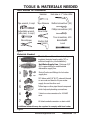
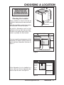
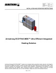
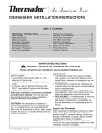
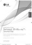
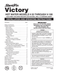
DISHWASHER
Installation
Instructions
LAVE-VAISSELLE
Instructions
d’installation
LAVADORA DE PLATOS
Instrucciones
de instalación
!
"
#
""
SHI66A,
SHU33A, SHU43C, SHU53A, SHU66C,
SHU43E, SHU53E, SHU66E,
SHV46C, SHV66A,
SHX33A, SHX46A, SHX46B, SHX56B,
SHY56A, SHY66C
$
$
$%
INTRODUCTION .................................................. .2
TOOLS AND MATERIALS NEEDED ......................... .3
MATERIALS SUPPLIED .......................................... .4
CHOOSING LOCATION ......................................... .5
PLUMBING PREPARATION .................................... .6
ELECTRICAL PREPARATION .................................. .7
PLACING THE DISHWASHER ................................ .8
DRAIN HOSE CONNECTION ................................. .9
HOT WATER CONNECTION .................................. 10
ELECTRICAL SUPPLY CONNECTION ...................... 11
GROUNDING INSTRUCTIONS ............................... 11
DOOR PANEL INSTALLATION ........................ 12 & 13
FINAL ADJUSTMENTS .......................................... 14
BASE AND TOE PANEL .......................................... 15
TOE PANEL AND HANDLE ..................................... 16
FINAL CHECKLIST ................................................ 17
ENGLISH
TABLE OF CONTENTS
IMPORTANT: Before you begin, read these instructions completely and carefully.
INSTALLER: Please leave this manual with owner for future reference.
OWNER: Save these installation instructions for local
electrical inspector’s use and for future reference.
www.boschappliances.com
ENGLISH - 1
INTRODUCTION
THESE INSTALLATION INSTRUCTIONS ARE INTENDED
FOR USE BY QUALIFIED INSTALLERS.
In addition to these instructions the dishwasher shall be installed:
•
•
In the United States, in accordance with the National Electric
Code/State and Municipal codes and/or local codes.
In Canada, in accordance with the Canadian Electric Code
C22.1 -latest edition/Provincial and Municipal codes and/or
local codes.
Please read these installation instructions completely and carefully.
They will save you time and effort and help to ensure optimum dishwasher
performance.
Be sure to observe all listed
warnings and cautions. (Look for
the triangles with exclamation marks
inside.)
WARNING
CAUTION
IMPORTANT
•
NEW INSTALLATION - If the dishwasher is a new installation, most of the work
must be done before the dishwasher is moved into place.
•
REPLACEMENT - If the dishwasher is replacing another dishwasher, the
connections for the dishwasher being replaced must be checked for
compatibility with the new dishwasher and replaced as necessary.
INSPECT THE DISHWASHER
After unpacking the dishwasher and prior to installation, thoroughly inspect the
dishwasher for possible freight or cosmetic damage. Report any damage immediately.
Cosmetic defects must be reported within 5 days of installation.
NOTE: Please do not discard any bags or items that come with the
original package until after the entire installation has been completed!
2 - ENGLISH
www.boschappliances.com
TOOLS & MATERIALS NEEDED
Tools Needed for Installation
"&%
+
!"
#$%&%
'(
'
ENGLISH
$$
)*
Figure 1
Materials Needed
Electric Connection - 2 conductor, 1 ground
insulated electrical supply cable (30” or
sufficient length for your installation).
Hot Water Supply Line - Minimum 3/8”
O.D. copper tubing or metal braided
dishwasher supply line.
Shut-off valve and fittings for hot water
supply line.
90° elbow with 3/8” N.P.T. external threads
on one end and sized to fit your water
supply line on the other end.
Teflon tape or other pipe thread compound
which help seal plumbing connections.
3 twist-on wire connectors for 16 AWG
wire.
UL listed conduit connector or strain relief.
Additional materials may be required to comply with local codes.
Figure 2
www.boschappliances.com
ENGLISH - 3
MATERIALS SUPPLIED
Accessory Parts Supplied
Accessory Parts for your model dishwasher will
come in one or more plastic bags. Check to
make sure that the parts supplied for your
model are all there. See Figure 3. If any parts
are missing contact your dealer immediately.
DISHWASHER
INSTALLATION KIT (Clear Bag)
D.
E.
F.
G.
Toe Panel Screws (8mm) (2)
Mounting Brackets (1L & 1R)
Mounting Bracket Screws (2)
Rubber Connection Hose (1)
and Drain Hose Clamps (2)
SHY66 & SHX56 Models
• Dishwasher Installation Kit (1) and
• (Green Bag) w/ the following:
L.
J-Box Cover (1)
M. J-Box Screw (8mm) (1)
N. Toe Panel Screw (4x16) (2)
SHV and SHI Models
• Dishwasher Installation Kit and
• Outer Door Installation Kit (Blue bag):
J.
SHI/SHV Panel Installation Template
C.
Cap (2 Blk)
K.
Wood Screws (2)
I.
Mounting Door Brackets(2 plastic)
w/Screws (4) and;
Mounting Door Brackets (2 metal)
w/Screws (4)
H. Spring Tension Screw (2)
Manual Bag
All Dishwashers come with a manual bag.
The following contents are located in every
bag:
• Use & Care Manual
• Installation Instructions
P. Tall Item Sprinkler (1)
SHY66 & SHX56 models
have an additional part:
Q. Cotton Insulation Strip (1)
Note: Pictures are not to scale.
4 - ENGLISH
Figure 3
www.boschappliances.com
CHOOSING A LOCATION
3-1/2” (90mm)
Choosing the Location
1-15/16” (49mm)
4” (102mm)
Figure 4
Any built-in dishwasher must be fully
enclosed on the top, both sides and back.
Therefore the cabinet space below your
counter is probably the best location.
23-9/16” (598 mm)
For proper operation and appearance of the
dishwasher, the cabinet opening should be
square and have dimensions as shown in
Figure 5.
90°
33-15/16” (862 mm)
minimum
Select a location as close to the sink as
possible for ready access to water and drain
lines.
Most of the installation work is done before
the dishwasher is moved into place.
ENGLISH
THESE INSTALLATION
INSTRUCTIONS ARE
INTENDED FOR USE BY
QUALIFIED INSTALLERS
90°
23-5/8” - 24-1/8” (600-613 mm)
Figure 5
Clearance
for door
opening
If the dishwasher is to be installed in a
corner, make sure there is adequate clearance to open the door. See Figure 6.
Dishwasher
Door in
open
position
Countertop
Figure 6
www.boschappliances.com
ENGLISH - 5
PLUMBING PREPARATION
THESE INSTALLATION
INSTRUCTIONS ARE
INTENDED FOR USE BY
QUALIFIED INSTALLERS
Drain Hose
The dishwasher comes with a seven (7)
foot drain hose.
• A 1.25” access hole must be made to
allow the drain hose to be run to the
drain connection location.
CAUTION
To protect against possible rupture of
the fill valve, water lines leading to
the dishwasher, as well as water lines
in the dishwasher MUST be protected
against freezing. If the valve or water
line freezes, flooding may occur. Such
ruptures are not covered by the
warranty.
IMPORTANT
Hot Water Supply
•
•
•
•
•
•
The hot water line to the dishwasher
must provide between 5 - 120 psi (0.38.27 bars) water pressure.
The hot water heater should be set to
deliver 140°F (60°C) water
temperature to the dishwasher.¹
A 3/8” minimum O.D. copper tubing
inlet line is recommended.
All solder connections must be made
before water line is connected to the
dishwasher’s inlet water valve. Do not
solder within 6 inches (152.4 mm)
of the dishwasher’s inlet water
valve.
Drill a 1” (25.4 mm) diameter access
hole in the cabinet for the water supply
line (Figure 9A).
Run the line to the approximate fill
valve location, as shown in Figure 9A.
If no air gap is used and the drain
line is run into a sink or disposer,
the drain line must be elevated to
a point higher than the highest
water level of the sink to prevent
back
siphoning
into
the
dishwasher.
NOTE: If connection to an air gap is
required by local code, air gap kits are
available from local plumbing sources.
Install the air gap according to the
manufacturer’s instructions.
Drain
Hose
It is recommended that a shut-off valve (not
supplied) be installed in the hot water
supply line in a readily accessible location,
see Figure 9.
Hot water
line
Electrical supply cable
Figure 7
1. In order to reduce running time, Bosch recommends 140° F water inlet
temperature. Your dishwasher will perform equally as well at 120° F water
temperature, but the run time will be extended.
6 - ENGLISH
www.boschappliances.com
ELECTRICAL PREPARATION
WARNING
23-5/8”-24-1/8”
(600-613mm)
3-1/2
(90 mm)
Electrical Supply
The customer has the responsibility to
ensure that the dishwasher installation is
in compliance with all national and local
electrical codes and ordinances. The
dishwasher shall be installed by a qualified
electrician and properly grounded. The
electrical supply for which the dishwasher
is designed is 120V, 60 Hz, AC, connected
to a dishwasher-dedicated electrical circuit
with a fuse or breaker rated for 15 amps.
If the dishwasher is connected with a food
disposer, a 20 amp (and no higher) fuse or
circuitbreaker may be used. No other
appliances or outlets should be connected
to the dishwasher supply circuit. Electrical
supply conductors shall be copper only and
shall be minimum #16 AWG. Wire
connectors proper for the size and number
of wires used to connect the dishwasher
to the supply circuit shall be used. Do not
use all-plastic wire connectors. Strip power
supply wires approximately ½ inch. Do not
pre-twist wire before applying wire
connector. After installing wire connectors,
gently tug wires to check the integrity of
the connector. Place all wires and
connectors into the power supply box,
and reinstall cover with the screw provided
in the installation package.
• Cut a 1” (25.4mm) diameter hole in the
cabinet (in area of Figure 9 B). For wood
cabinets, sand the hole until smooth.
For metal cabinets, cover the edge with
a grommet.
• Run flexible cable (as codes permit) from
junction through hole in cabinet. Cable
should extend 30” (762 mm) from back
wall.
ENGLISH
THESE INSTALLATION
INSTRUCTIONS ARE
INTENDED FOR USE BY
QUALIFIED INSTALLERS
1-5/16
(49 mm)
Figure 8
Electrical Rating
Volts
Hertz
Amperes
Watts
120
60
15
1,450
(max)
Table 1
Openings for electrical lines must be
installed in the marked areas as
shown in Figures 8 and 9 to avoid
interference with the dishwasher
frame or other components.
Shut-off
valve
HWS
A
B
14”
(355 mm)
21”
(533 mm)
Hot water supply line
Electric supply cable
Figure 9
www.boschappliances.com
ENGLISH - 7
PLACING THE DISHWASHER
Placing the Dishwasher
The profile strips on the sides of the
dishwasher allow the dishwasher to fit into
a cabinet opening with a width of 23-5/8”
(600 mm) to 24-1/8” (613 mm). Before
sliding the dishwasher into the cabinet
opening:
•
•
•
•
•
Straighten the hot water supply line and
the electrical cable (see Figure 11).
Level & Align (initial adjustments).
Guide the drain hose carefully (avoiding
kinks in hose) as the dishwasher is slid
into the cabinet opening.
Make final leveling adjustments (see
FINAL STEPS Section).
To maintain the dishwasher position and
alignment, first determine which type
of mounting your dishwasher needs:
Top Mount is used for all types of
countertops that will not be damaged
by drilling.
•
For a top mount, position the
brackets flat on each of the top
corners of the dishwasher as
shown in Figure 10A.
Side Mount is used when there is a
granite, marble or other hard natural
surface counter top that could be
damaged by drilling.
•
For a side mount, bend the
brackets, then position them as
shown in Figure 10B.
•
•
A. Mounting bracket
for mounting to under
countertop
B. Mounting bracket
bent for mounting to
side of cabinets
Figure 10
IMPORTANT
If you wish to change the front panel of
the dishwasher this must be done before
sliding the dishwasher into place.
*Note: Additional accessory door panels can not be used with SHU 9900
models.
Lev
el
Drive Mounting Screws (see Figure 3)
through the holes in the brackets. See
Figure 10A or 10B.
Connect the drain hose, hot water
supply line and electrical connections
as described in the following sections.
Figure 11
8 - ENGLISH
www.boschappliances.com
DRAIN HOSE CONNECTION
Drain Hose
in Sink with
Air Gap/ No
Disposer
Rubber
Connector
min. 20” (500 mm)
clearance to floor
Be sure to follow your national
and local codes at all times.
Air Gap
Drain Hose
Trap
ENGLISH
THESE INSTALLATION
INSTRUCTIONS ARE
INTENDED FOR USE BY
QUALIFIED INSTALLERS
Figure 12
Air Gap
Drain Hose
in Sink
with Air
Gap &
Disposer
min. 20” (500 mm)
clearance to floor
• Before beginning, turn off the water
supply!
• The access hole for the drain hose should
be 1.25” (32 mm) diameter.
• Use the hose clamps and rubber
connection hose (Figure 3) to connect
the drain hose to the sink, disposer or
air gap (Figure 14).
Openings for drain lines must be
installed in the marked areas as
shown in Figures 8 and 9 to avoid
interference with the dishwasher
frame or other components.
CAUTION
Rubber
Connector
disposer
Trap
Figure 13
Drain Hose
Connected
to Sink
G, Fig 3
Failure to provide the proper drain
connection height, 20” (508mm)
above floor level with high loop or
air gap, will result in improper
draining of the dishwasher.
Improper draining may cause
damage to the dishwasher.
Figure 14
www.boschappliances.com
ENGLISH - 9
HOT WATER CONNECTION
THESE INSTALLATION
INSTRUCTIONS ARE
INTENDED FOR USE BY
QUALIFIED INSTALLERS
Shut off valve
(not included)
Connecting the Hot Water
Supply Line
• If using a solder joint instead of a compression fitting, be sure to make all
solder connections before connecting
the water line to the dishwasher.
• Make sure there are no sharp bends or
kinks in the water line which might
restrict water flow.
• When connecting threaded pipe use pipe
thread compound or Teflon tape to seal
the connection.
• Before connecting the copper hot water
supply line to the dishwasher, it should
be flushed with hot water to clear any
foreign material.
• Apply Teflon tape or other pipe sealant
to 90° elbow fitting and connect
directly to water inlet valve*.
• Turn on the water supply to check for
leaks after making connections.
Figure 15
CAUTION
DO NOT SOLDER WITHIN 6 INCHES
(152.4 MM) OF THE DISHWASHER’S
INLET VALVE.
TEMPERATURES REQUIRED FOR
SOLDERING WILL DAMAGE THE
VALVE!
* Water inlet valve located at the bottom
left front of the dishwasher.
Openings for water lines must be
installed in the marked areas as shown
in Figures 8 and 9 to avoid
interference with the dishwasher
frame or other components.
Figure 16
10 - ENGLISH
www.boschappliances.com
ELECTRICAL SUPPLY CONNECTION
Connecting Electrical Supply
Be sure to follow all local and national electrical codes and ordinances.
• Install strain relief or conduit connector
into opening on power supply box.
• Strip the insulated wires, being extremely
careful not to strip too much insulation.
• Insert and securely fasten into strain relief, two-conductor supply cable with
ground.
• Twist wire connectors tightly onto the
wires, ensuring that no bare wiring is
exposed (from insulated wires).
• Press wires back into J-box
• Securely fasten the J-box cover or toe
panel (depending on model) with
screw(s) provided from accessories
package.
WARNING
ELECTRICAL SHOCK HAZARD
ENGLISH
THESE INSTALLATION
INSTRUCTIONS ARE
INTENDED FOR USE BY
QUALIFIED INSTALLERS
• DISCONNECT ELECTRICAL POWER
AT THE CIRCUIT BREAKER BOX OR
FUSE BOX BEFORE INSTALLING THE
DISHWASHER.
• ELECTRICALLY GROUND DISHWASHER.
• USE COPPER CONDUCTORS ONLY.
FAILURE TO FOLLOW THESE
INSTRUCTIONS COULD RESULT IN
SERIOUS INJURY OR DEATH.
Correct Connection in Junction Box
Black to Black
White to White
Green or Bare
to Green or Bare
U.L. listed
Conduit
Connector
or Strain
Relief
* Junction box located at the bottom
right front of the dishwasher base.
Figure 17
Grounding Instructions
This appliance must be connected to a
grounded metal permanent wiring system;
or an equipment grounding conductor
must be run with the circuit conductors
and connected to the equipment grounding
terminal or lead on the dishwasher. The
dishwasher must be properly grounded
before operating. Make sure that the
dishwasher is connected to a suitable
ground in compliance with the NATIONAL
ELECTRICAL CODE, in the United States,
or the CANADIAN ELECTRIC CODE C22.1latest edition, in Canada as well as any provincial/state or municipal or local codes that
apply.
Incorrect Connection in Junction Box
Figure 18
www.boschappliances.com
ENGLISH - 11
DOOR PANEL INSTALLATION
Accessory Panel Installation SHU Models
If you have an SHU model and have ordered an accessory panel kit it must be installed
prior to sliding the dishwasher into place. Dimensions of panel size that may be used is
shown in Figure 19.
Panel Installation, SHV Models
If you have an SHV model, a fully integrated model, you will have additional mounting
hardware and a folded template sheet with installation instructions comprised of
pictograms.
Refer to the folded template sheet for information on how to mount the panel. Please
note that one side of the template shows how to mount a one piece panel and the other
side of the template shows how to mount a two piece panel. Be sure of what type
installation you want before proceeding with the installation.
Refer to Figure 20 and Table 3 for guidelines on custom door panel selections.
After deciding if the extension pieces will be used or not refer to the pictograms printed
on the template for proper method of mounting your custom door.
Panel Installation, SHI Models
If you have an SHI model, an integrated model, you will have additional mounting
hardware and a folded template sheet with installation instructions comprised of
pictograms. In North America the stainless steel models of the integrated series (SHI
series), have a control panel that is 5-5/16” (135 mm) tall. The stainless steel model
comes with two extension pieces, referred to as the standard and long extension piece
in Table 2: the standard piece is used for drawer heights up to 6” (152mm); the long
extension piece is used for drawer heights greater than 6” (152mm) but 6-7/16” (164mm)
or less. These stainless steel extension pieces are not installed in the control panel. In
the stainless steel models, the two extension pieces are shipped loose and must be
inserted as shown in pictogram 5 on the template sheet.
The purpose of the extension piece is to allow the increase of the control panel height to
try to match the horizontal drawer line of the cabinets. If your drawers are taller than the
“C” dimension shown on Table 2, it is recommended that the extension either be slid in
as far as it will go, or removed and the door made to fit directly below the control panel.
12 - ENGLISH
www.boschappliances.com
DOOR PANEL INSTALLATION
25”
(636 mm)
ENGLISH
SEE FOLDED PANEL INSTALLATION
TEMPLATE SHEET FOR STEP BY STEP
INSTRUCTIONS ON HOW TO INSTALL
YOUR DISHWASHER PANEL(S).
1/4” max.
(6 mm)
23-1/16”
(586 mm)
Figure 19
IMPORTANT
Do NOT Drill Completely through
your custom door panel.
EXTENSION "A"
MAX.-MIN.
MODEL
SHI66C05UC
"C "
MAX.-MIN.
"B"
STANDARD
11/16 - 5/16"
(18-8mm)
LONG
1 1/8 - 11/16" 5 5/16 (135 6 7/16 - 5 5/8
(29 - 18mm)
mm)
(164 - 143 mm)
Table 2
Figure 20
MODEL
D
E*
F
SHV
N/A
27 3/16" - 30 5/16"
(690 - 770 mm)
SHI
20 11/16 - 25
(526-635 mm)
27 3/16" - 30 5/16"
(690 - 770 mm)
23 3/16 - 23 3/8
(589 - 594 mm)
Table 3
Figure 21
*Note: Do not exceed 30 5/16” (770mm)
for the overall front panel length.
www.boschappliances.com
ENGLISH - 13
FINAL ADJUSTMENTS
Door Tension Adjustment
(only in SHI and SHV models)
After installation of the dishwasher, open
and close the door several times to make
sure that it does so with ease. If the door
closes too quickly or if the door falls open,
the spring tension needs to be adjusted.
•
•
To Adjust the Spring Tension
Obtain Spring Tension Screws (2) out
of the SHI/SHV parts bag (see Figure
3).
Insert the screws in the right and left
sides and adjust spring tension as shown
(see Figure 22).
Adjust screws
on right and
left sides
Torx T 20
Figure 22
Leveling the Dishwasher
Raising the Rear
The rear leveling leg is adjusted by turning
the center screw at the front of the
dishwasher.
Torx T 20
Raising the Front
The front leveling legs are adjusted by
rotating the leveling legs on the front left
and right sides of the dishwasher.
• Use a screwdriver and tap the end lightly
with a hammer to turn the legs (see
Figure 23).
Figure 23
Note: If additional height is needed:
Shims may be added under the leveler feet.
14 - ENGLISH
www.boschappliances.com
BASE AND TOE PANEL
SHY66 & SHX56 Series Base and Toe Panel Installation
Steps
SHY66
& SHX56 BASE PARTS
Installation Parts
SHY66 & SHX56 Base Part
Base Part Screws
SHY66 & SHX56 Toe Panel
SHU Toe Panel Screws
SHY66 & SHX56 Installation Kit
(Refer to “Materials Supplied” section)
!"
Remember to carefully check, the “Materials
Supplied” section against the Installation Kit
bag and contents.
Figure 24
ENGLISH
•
•
•
•
•
Disassembly Steps
•
•
•
Pull Toe Panel off (Figure 25).
Loosen Screws
LOW TORQUE, USE HAND TOOL
ONLY.
Remove Base Part by pulling it out
and downward.
After installation, water and electrical
lines are connected and the unit leveled,
assemble the base part (see below).
Figure 25
Assembly Steps
•
•
•
•
Place J-Box Cover on J-Box, insert
and tighten screw (Figure 26).
Drop screws inside holes in base part.
Slip Base Part under and up front
bottom panel of dishwasher. Tighten
Base Part Screws - LOW TORQUE,
USE HAND TOOL ONLY.
Slip Cotton Insulation Strip under
unit, between the bottom of Base
Figure 26
Part and the floor.
Junction Box Cover is required
for any installation application
www.boschappliances.com
ENGLISH - 15
TOE PANEL AND HANDLE
Regular Toe Panel
Installation (for models
other than SHY66 & SHX56)
• Obtain Toe Panel Screws from the
Dishwasher Installation Kit bag (see
Figure 3).
• Insert screws through the Toe Panel.
• With a Torx screwdriver, fasten screws Figure 28
and toe panel into dishwasher base.
16 - ENGLISH
www.boschappliances.com
FINAL CHECKLIST
Final Checklist
ENGLISH
Check Electrical Requirements.
Be sure you have correct electrical supply and recommended grounding method.
Turn on the hot water shut-off valve and electrical supply. Incoming water
temperature should be 120°F-140°F (49°C-60°C).
Operate the dishwasher through one cycle and check for plumbing leaks.
If the dishwasher does not operate properly, refer to the SELF- HELP, CUSTOMER
SERVICE and WARRANTY sections in the Use and Care Manual.
Customer Service Information
If service becomes necessary, contact your dealer or installer or an authorized service center. Do
not attempt to repair the appliance yourself. Any work performed by unauthorized personnel may
void the warranty. If problem persists, take the following steps (in the order listed below) until the
problem is corrected to your satisfaction.
1.
2.
3.
Contact your installer or the Bosch Authorized Service Contractor in your area.
E-mail us from the Customer Service section of our web site, www.boschappliances.com.
Write to us at the address below:
BSH Home Appliances, Corp.
5551 McFadden Avenue
Huntington Beach, CA 92649
4.
Call us at: 1-800/944-2904.
Please be sure to include (if writing), or have available (if calling), the following information:
•
Model Number
•
•
Serial Number
Date of Original Purchase
•
Date Problem Originated
•
Explanation of Problem
Also, if writing, please be sure to include a daytime phone number.
(You will find the model number and serial number information on the label located on the right-hand
side of the inner door of the dishwasher).
LEAVE INSTALLATION INSTRUCTIONS AND
USE & CARE MANUAL WITH OWNER.
www.boschappliances.com
ENGLISH - 17
18 - ENGLISH
www.boschappliances.com