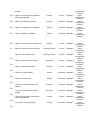
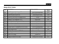
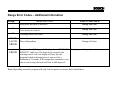
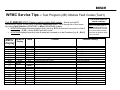
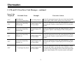
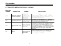
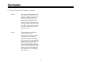
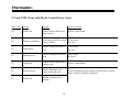
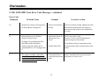
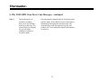
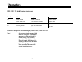
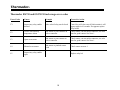
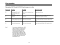
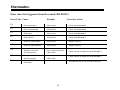
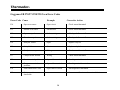
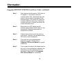
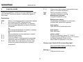
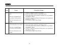
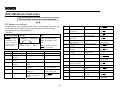
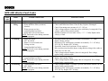
1
Thermador
Professional Ranges Models: PDR30/36/48…PRG30/36/48
The control continuously monitors system parameters for control and oven failures and reports a fault code
when a system problem is detected. The control utilizes the ovens blue “on light” and oven “heating light” to
report a detected fault code. The control will continue to flash the lights in the appropriate sequence as long as
the fault exists.
Detection of a fault does not hinder the ability of the control to continue to function if the fault is not critical for
the intended operation. For example: If the range door latch is inoperative, the range will continue to cook since
the fault would only prevent the range from self-cleaning.
ERROR CODE
LIGHT SEQUENCE CODE
E1
E2
E3
E4
E5
E6
E7
E9
E11
E12
E13
E14
22
01
10
12
21
32
23
43
44
11
13
55
DESCRIPTION
EEPROM ERROR
CONTROL NOT CALIBRATED
SENSOR OPEN
SENSOR SHORTED
POTENTIONMETER FAILURE
OVER TEMPERATURE-COOKING
OVER TEMPERATURE-CLEANING
NO COOLING FANS
DOOR LATCH FAULT
EXP. BOARD NOT CONNECTED
VCC LIFT OFF ERROR
SELECTOR SWITCH ERROR
Thermador
HOW TO INTERPRET CODES
When a fault occurs, the control will flash the blue oven “on light” and the Blue “heating light” sequentially to
indicate the fault. The fault codes have two numbers, these numbers are interpreted by the number of times the
lights flash. The oven “on light” will flash indicating the first number, and the “heating light” will flash indicating
the second number.
EXAMPLE:
Error E9 is…. No Cooling Fans. The code is 43. The oven “on light” will flash four times, then the “heating light”
will flash three times, then pause. The sequence will then repeat as long as the fault is present.
ERROR CODES FOR OVENS WITH DREEFS CONTROL
The following chart shows the error codes
that can be displayed in the Oven/Selector
window during specific oven malfunctions.
Some of the error messages can be
cleared by performing the following steps:
1. Turn the selector knob to OFF
2. “Tweak” the oven by turning the
selector knob slightly to the left
(counterclockwise). This may stop
the flashing message/beeping and
clear the window.
3. For errors E1, E9, E11, E12 and
E13, the power supply going to the
even must be turned off
momentarily, and back on again
4. If an error remains displayed when
the selector switch is OFF, and after
attempting to clear the display, as
shown in steps 2 and 3, turn off the
power going to the oven, and refer to
the chart below to help you find the
problem.
ERROR
ERROR CODE DESCRIPTION OF PROBLEM
MESSAGE NOTES
Control board problem.
E1
C&E
Cook or Clean mode runaway (temp >635 °F). Clean mode runaway
E2
G&K
E3
E4
E5
E6
E7
E8
E9
E10
E11
E12
E13
A&H
A&H
K& D
C&J
A&I
A&D
A&E
B&D
A&F
A&E
A&C
E14
E15
A&E
B&D
(clean temp +32 °F).
Open oven temperature sensor (>5000 Ω).
Shorted oven temperature sensor (<5000 Ω).
Control board too cold, too hot, or defective.
Control board problem.
Illegal temperature display. Turn off oven and try again.
Control board problem.
Latch switch problem.
Control board problem.
CT oven – latch switch problem
CT ovens – latch switch problem
CT ovens – latch frozen or no power to latch motor.
CMT ovens – control board not converted (refer to page 3-7 for
conversion data).
Latch switch problem.
Control board problem.
ERROR CODE NOTES:
A
B
C
D
E
F
G
H
I
J
K
L
Turns heat off on the failed oven only; microwave not affected.
Turns all heat off; microwave not affected.
Disables the CLEAN mode in both ovens; allows COOK and microwave.
Error will remain in the display until oven is repaired and powered back up. No error tones.
Turning the oven off stops the error and flashing display. Can tweak away the error code. Error is
redisplayed only if the selector is turned to CLEAN.
Tweaking clears to “---“ for retry.
Clears when the oven temperature is less then the runaway temperature with the selector switch off.
Can be cancelled by tweaking if a good sensor is detected.
Cleared with a mode change.
Can be tweaked away for immediate retry. User must unlatch and delete the “---“ to try to relatch the
door.
Turns heat and microwave off.
If two switches show a locked door, then E13 and LOCK are permanent in the display (in all modes).
If the two switches show an open door, tweak away the E13 error message.
EMERSON APPLIANCE CONTROLS
DIVISION OF EMERSON ELECTRIC CO.
Product Specification for Sago Oven Control
13. DIAGNOSTIC CODES
13.1
DOCUMENT: 92S21720100
REVISION: B
PAGE:
DeBounce is the Rate at which the error checking occurs
Diagnostic Code Checking
The following chart describes the Fault code structure for the Control.
Alarm fault monitor is always active. Any oven cancel key will reset
the display to TOD idle.
CODE
DESCRIPTION
F13
Upper oven RTD not calibrated
F14
Display board EEPROM error
F19
F23
WHEN CHECKED
Always
DEBOUNCE
ERROR
ACTION
MESSAGE TAKEN BY
DISPLAYED CONTROL
10 seconds Message 1
Cancel
cooking/timing
functions
Oven Programming
5 tries
Message 1
Cancel
cooking/timing
functions
Power board Communication error
Always
20 seconds
Message 1
Cancel
cooking/timing
functions
Always
20 seconds
Message 1
Cancel
cooking/timing
functions
F24
Keyboard gain unstable
Keyboard scratches
Loose molex or pins, air pocket in
control
Keyboard disconnected
Always
20 seconds
Message 1
Cancel
cooking/timing
functions
F25
Keys stuck
Always
20 seconds
Message 1
Cancel
cooking/timing
functions
F26
Keys moving/dropping out
Always
20 seconds
Message 1
Cancel
cooking/timing
functions
F30
Upper oven sensor shorted
Always
20 seconds
Message 1
Cancel
cooking/timing
functions
F31
Upper oven sensor open
Always
20 seconds
Message 1
Cancel
cooking/timing
functions
F32
Upper oven over temperature while
cleaning
Cleaning
20 seconds
Message 1
Cancel
cooking/timing
functions
F33
Upper oven over temperature while
Non-Clean
20 seconds
Message 1
Cancel
cooking
cooking/timing
functions
Message 1
Cancel
cooking/timing
functions
F34
Upper oven cooling fan over-speed or
under-speed detected
Cooking
1 minute
F40
Upper oven meat probe shorted
Cooking
20 seconds
Message 1
Cancel
cooking/timing
functions
F41
Upper oven meat probe not calibrated
Always
10 seconds
Message 1
Cancel
cooking/timing
functions
F43
Lower oven RTD not calibrated
Always
10 seconds
Message 1
Cancel
cooking/timing
functions
F50
Upper oven door latch signal shorted low
Always
1 minute
Message 1
Cancel
cooking/timing
functions
F51
Upper oven door latch stuck unlocked
Cooking/ Cleaning
1 minute
Message 1
Cancel
cooking/timing
functions
Upper oven door position error
Cooking/ Cleaning
1 minute
Message 1
Cancel
cooking/timing
functions
Non-Clean
1 minute
Message 1
Cancel
cooking/timing
functions
Cleaning
1 minute
Message 1
Cancel
cooking/timing
functions
Lower oven sensor shorted
Always
20 seconds
Message 1
Cancel
cooking/timing
functions
Lower oven sensor open
Always
20 seconds
Message 1
Cancel
cooking/timing
functions
Lower oven over temperature while
cleaning
Cleaning
20 seconds
Message 1
Cancel
cooking/timing
functions
Lover oven over temperature while
cooking
Non-Clean
20 seconds
Message 1
Cancel
cooking/timing
functions
Lower oven cooling fan over-speed or
under-speed detected
Cooking
1 minute
Message 1
Cancel
cooking/timing
functions
Lover oven meat probe shorted
Cooking
20 seconds
Message 1
Cancel
cooking/timing
functions
F52
Upper oven door latch stuck locked
F53
Upper oven latch input shorted
F54
F60
F61
F62
F63
F64
F70
Lower oven meat probe not calibrated
Always
10 seconds
Message 1
Cancel
cooking/timing
functions
Lower oven door latch signal shorted low
Always
1 minute
Message 1
Cancel
cooking/timing
functions
Lower oven door latch stuck unlocked
Cooking/ Cleaning
1 minute
Message 1
Cancel
cooking/timing
functions
Lower oven door position error
Cooking/ Cleaning
1 minute
Message 1
Cancel
cooking/timing
functions
Lower oven door latch stuck locked
Non-Clean
1 minute
Message 1
Cancel
cooking/timing
functions
Lower oven door latch input shorted
Cleaning
1 minute
Message 1
Cancel
cooking/timing
functions
F71
F80
F81
F82
F83
F84
B
Range Error Codes
CODE
DESCRIPTION
Oven temperature sensor failure
WHEN CHECKED
Cook or clean programmed
When W. Drawer is active
Latch should be locked
Latch should be unlocked
Always
Latch unlocked
Latch locked
Always
FAULT
LIMIT
20 sec
20 sec
1 min
1 min
1 min
5 sec
5sec
1 min
Always
1 min
Always
Cook or clean programmed
Always
1 min
1 sec
1 sec
1 sec
1 sec
F31
F33
F41
F43
F45
F111
F113
F121
Warning Drawer Sensor Failure
Motorized latch will not lock
Motorized latch will not unlock
Motorized Latch both locked and unlocked
Runaway Oven temperature 585°F
Runaway Oven temperature 950°F
Stuck key in the membrane switch layer
F125
Cancel key circuit problem
F141
F151
F153
F154
F155
Slave micro not functioning
Eeprom failure or communication circuit failure
User Interface too hot
Power Board too hot
Cook profile corrupted in EEPROM
Cook or clean Programmed
F170
F190
F200
F210
Power Failure
Power over voltage
Time out and stop function
Range exceeded safe test limits
Always
At power on
During Production test mode
During Service test mode
Always
2 ms
110 sec.
200°F
B
Range Error Codes – Additional Information
CODE
F1
F2
F3
DOOR
LATCH
ERROR
ERROR
DESCRIPTION
WHEN CHECKED
Meat probe not there or incorrect
During Test / use
Oven sensor not correct
During Test / use
Warming sensor not correct
During Test / use
Door latch problem
During self-clean
Temp. reaches 585 degrees F. Display shows “CONTACT During any cooking mode
SERVICE” and beeps. The beep can be stopped with
touching cancel zone, but display will stay up with
program locked until main power is removed for a
minimum of 5 seconds. If the temperature continues to rise
(due to stuck relay) the latch will lock at 600 degrees F
Note: Depending on model, program will only look for probes or sensors that it should have.
B
WFMC Service Tips – Test Program (2B): Module Fault Codes (Test1)
Last 8 fault codes are
stored & display!
Test P1:ERRORS / P:01 (Viewing control module fault codes) – Start & end test P1
(WFMC6400) / (P:01) (WFMC3200) by pushing Start/Pause button. Scroll through list of fault codes
by pushing Spin Selection (WFMC3200) or Menu (WFMC6400) buttons.
• WFMC3200 display alternates between fault code (e.g. E:01) & when fault occurred on in last 8
washes (e.g. : C:00) – shows C:00 if fault didn’t occur.
• WFMC6400 display shows fault code & when fault occurred on in last 8 washes (e.g. 0 – Er:01)
WFMC32
Display
WFMC64
Display
Test #
E:01
E:02
E:03
E:04
E:05
E:06
E:07
E:08
E:09
Er:01
Er:02
Er:03
Er:04
Er:05
Er:06
Er:07
Er:08
Er:09
washing
washing
washing
washing
P:16
------E:12
E:13
E:14
------E:20
E:21
E:22
E:24
Er:10
Er:11
Er:12
Er:13
Er:14
Er:15
Er:16
Er:20
Er:21
Er:22
Er:24
P:16
P:16
P:16
P:4
P:11
P:8/9/13
P:8/9/13
P:15
P:9
P:8
P:8
P:4
washing
P:4
Problem
Door open
Door lock doesn’t unlock
Door lock doesn’t lock
Door control broken
NTC open-circuited
NTC shorted
Unpexpected heating (heater on at wrong time)
Heater doesn’t shut off
Communication lost to motor
Flow meter gives wrong values
No water flow (within 6 minutes)
Water supply time exceeded
Drian pump time exceeded
Overflow level exceeded
Pressure sensor gives failure voltage level
Can’t calibrate pressure sensor
Spinning aborted due to unbalanced load
Excessive foam
Frequency synchronization failed
Motor power relay failed
HINT: # of faults reads “0”
for faults which didn’t occur.
Look at # of faults, not error
#, to see if faults occurred –
scroll thru all faults to check
if any occurred.
Possible Cause(s)
Door lock not engaged
Jammed lock or bad wire harness
Jammed lock or bad wire harness
Faulty Triac or control module
Faulty NTC or bad wire harness
Faulty NTC or bad wire harness
Faulty heater or stuck heater relay
Faulty heater or stuck heater relay
Faulty wire harness
Faulty flow meter or wire harness
Faulty inlet valve, wire harness, hose
Faulty inlet valve, wire harness, hose
Faulty drain pump, wire harness, hose
Faulty/blocked pump, hose, inlet valve
Faulty pressure sensor, wire harness
Faulty pressure sensor, wire harness
Unbalanced load or faulty wire harness
Wrong or too much detergent used
Faulty control module
Faulty control module
B
WFMC Service Tips – Test Program (2C): Motor Control Fault Codes
(Test1)
Last 16 fault codes are
stored & display!
Test P1:ERRORS / P:01 (Viewing motor control fault codes) – Start & end test P1 by
pushing Start/Pause button. Scroll through list of (18) fault codes by pushing Spin Selection
(WFMC3200) or Menu (WFMC6400) buttons.
• WFMC3200 display alternates between fault code (e.g. d:01) & when fault occurred on in last
16 washes (e.g. : C:00) – shows C:00 if fault didn’t occur.
• WFMC6400 display shows fault code & when fault occurred on in last 16 washes (e.g. 0 – Er:01)
WFMC32
Display
WFMC64
Display
d:01
d:02
d:03
d:06
d:07
d:08
d:09
d:10
d:11
d:12
d:13
d:14
d:15
d:16
d:17
d:18
dr:01
dr:02
dr:03
dr:06
dr:07
dr:08
dr:09
dr:10
dr:11
dr:12
dr:13
dr:14
dr:15
dr:16
dr:17
dr:18
Test #
P:04
P:04
P:04
P:04
P:04
P:04
P:04
P:04
P:04
P:04
P:04
P:04
P:04
P:04
P:04
P:04
Problem
Motor control short circuit
Motor control interruption
Damaged motor control temperature sensor
NTC relay failure
Motor winding short circuited
Motor speed sensor failed
Voltage too high
Power limiter switch off
Voltage too low
Motor control high current switch off
Motor control high temperature switch off
Motor control high temperature warning
Power limiter warning
Motor high temperature switch off
Motor high temperature warning
Peak voltage too high
HINT: # of faults reads “0”
for faults which didn’t occur.
Look at # of faults, not error
#, to see if faults occurred –
scroll thru all faults to check
if any occurred.
Possible Cause(s)
Faulty motor control.
Faulty motor control.
Faulty temperature sensor.
NTC too hot or relay stuck closed.
Motor winding short circuited.
Faulty speed sensor or wire harness.
Faulty motor control.
Motor overloaded or binding.
Faulty motor control.
Motor overloaded or binding.
Motor overloaded or binding.
Motor overloaded or binding.
Motor overloaded or binding.
Motor overloaded or binding.
Motor overloaded or binding.
Faulty motor control.
B
WTMC Service Tips - - Test program (4A): Fault Codes
WTMC Dryer Test Program Fault Codes
Fault
Code
Fault
Overheating due to
clogged lint filter.
Severe overheating
due to clogged lint filter.
Solution
Clean lint filter (&air duct if
necessary).
Clean lint filter (&air duct if
necessary).
Notes
Displays E:01 during normal use.
Measures reduced air flow.
Displays E:01 during normal use.
Measures reduced air flow.
E:13
Maxium drying time
exceed
E:17
NTC error (NTC R3 @
lint screen)
NTC error (NTC R2 @
heater)
Check heater, control module, NTC’s
& Hi-limits. Usually faulty heater. Can
also be overloaded dryer.
Check NTC R3 & wire harness.
Replace faulty part.
Check NTC R2 & wire harness.
Replace faulty part.
Stops & displays E:03 during
normal use (after maxium drying
time limit of 240 minutes).
Typically shorted or opened wire
harness.
Typically shorted or opened wire
harness.
E:20
EEPROM error
Replace faulty control module.
Dryer stops &
can’t be restarted.
E:21
Incorrect checksum
Replace faulty control module.
Dryer stops &
can’t be restarted.
E:22
Invalid update
Replace faulty control module.
Dryer stops &
can’t be restarted.
E:11
E:12
E:18
Effect
.
Dryer stops &
can’t be restarted.
Dryer stops &
can’t be restarted.
NOTE: To run fault codes tests to display fault codes:
•
While pushing & holding Start/Stop & Delicates button, rotate cycle selector knob to Extra Dry – Regular/Cotton.
•
Push Start/Stop button to start test. Push Start/Stop button to scroll through fault codes (if more than one exists). Do not rotate
knob through Off to avoid exiting test program.
•
Rotate cycle selector knob to end test.
B
WTMC Service Tips - - Test program (4B): Fault Codes
WTMC Dryer Test Program Fault Codes
Fault
Code
E:23
Fault
Model variant doesn’t
match table
Solution
Replace faulty control module.
E:24
Software version
doesn’t match table
Replace faulty control module.
E:25
Damaged data table
Replace faulty control module.
E:26
Control error
Replace faulty control module.
NOTE: Fault displayed alternates with # of times fault occurred every
two (2) seconds. If there’s no faults, displays will be blank.
• E:xx = fault code from E11 – E39 (e.g. E:11)
• C:xx = # of occurrences (e.g. C:01)
NOTE: When test program is initially entered,
last fault code will show. Display will be cleared
once any test is started.
Notes
Effect
Dryer stops &
can’t be
restarted.
Dryer stops &
can’t be
restarted.
Dryer stops &
can’t be
restarted.
Dryer stops &
can’t be
restarted.
B
Service Tips – Fault Codes (1)
DISHWASHER TEST PROGRAM ERROR CODES (on 2&3-digit digital displays):
0- No faults
1- Aqua Sensor (Sensotronic) fault
2- Heating system fault (heater, Hi-Limit, flow switch, NTC, control heater relay)
4- Water filling fault
TIP: Fault codes add up for multiple faults
8- NTC (temperature sensor) fault
(e.g. heating + water filling fault = 2 + 4 = 6
16- Water switch fault
DISHWASHER TEST PROGRAM ERROR CODES (on 2&3-digit digital displays):
FWater filling fault (underfill, overfill or water in the base)
2HLast wash cycle too long (> 99 minutes). Can be cold inlet water or heating
system fault (heater, Hi-Limit, flow switch, NTC, control module heater relay).
FDelay Start feature (not a fault code)
DISHWASHER TEST PROGRAM ERROR CODES (on lower
line of full text Apexx SH 99 displays):
S3 - No faults
A – Aqua Sensor (red) fault
B – Aqua Sensor (green) fault
E – Water switch fault (no pulses detected)
F – Water filling fault
G – Water switch fault (won’t stop running)
H – Heating system fault (heater, Hi-Limit, flow switch,
NTC, control module heater relay)
K- NTC fault (short-circuited or open-circuited)
Xx – Test program step count (testing done when = 00)
TIP: Top line shows wash cycle & bottom line shows fault code.
HINT: Dishwasher test program heat water to
150°F, so test programs will generally run > 20
minutes for incoming water temperatures ~ 120°F
00
000
00
000
HINT: Apexx
heater
runs
during steps
05
08.
Press
“-“
button to skip
to test 05 to
measure
heater
amp
draw.
◄ S- - 3- - - - - - - - - - - - - - - - ►
Start ►
In Cycle
S3
0--------------
►
◄ STEP
S3
00
S3
00
HINT: Open door to select test
program for fully-integrated models,
then close door to run program.
NOTE: Flow through
heaters heat water ~
2°F/minute.
B
Service Tips – Fault Codes (2)
DISHWASHER TEST PROGRAM ERROR CODES (on SHX33A/43E/46A-B, SHV46C, SL84A models):
●○○ – Heating system fault (heater, Hi-Limit, flow switch, control heater relay)
○●○ – NTC (temperature sensor) fault
○●● – Water filling fault
●○○ – N/A
SHV46C, SHX43E/46A-B, SL84A
●○● – N/A
●●○ – Aqua sensor (sensotronic) fault
SHX33
●●● – N/A
Fault code LED’s
Top
Rack
Power
Scrub
Reg.
Wash
Del./
Econo
Power
Scrub
Reg.
Wash
Rinse
& Hold
Rinse
& Hold
TIP: Fault codes do NOT add up for multiple faults – shows highest fault code
on list above (1st – heating, 2nd – NTC, 3rd – water filling, 4th – aqua sensor)
DISHWASHER TEST PROGRAM ERROR CODES (on SHU43E/53E/66E models):
Fa ults
0 - N o fa ults
1 - H e a te r E le me nt
2 - W a te r Filling
3 - NTC
4 - Aqua se nsor
LE D Fa ult Code s
READY
CYCLE
CLEAN
NSF
READY
CYCLE
CLEAN
NSF
READY
CYCLE
CLEAN
NSF
READY
CYCLE CLEAN
NSF
READY
CYCLE CLEAN
NSF
LED flashes
LED lit
LED off
NOTE:
Flow
through heaters heat
water ~ 2°F/minute.
HINT: Open door to select test
program for fully-integrated models,
then close door to run program.
HINT: Dishwasher test program heat water to
150°F, so test programs will generally run > 20
minutes for incoming water temperatures ~120°F.
B
Thermador
BSH HOME APPLIANCES CORPORATION
ERROR CODES
For products with electronic controls
B
Thermador®
Thermador
Professional Ranges Models: PDR30/36/48…PRG30/36/48
The control continuously monitors system parameters for control and oven failures and reports a fault code
when a system problem is detected. The control utilizes the ovens blue “on light” and oven “heating light” to
report a detected fault code. The control will continue to flash the lights in the appropriate sequence as long as
the fault exists.
Detection of a fault does not hinder the ability of the control to continue to function if the fault is not critical for
the intended operation. For example: If the range door latch is inoperative, the range will continue to cook since
the fault would only prevent the range from self-cleaning.
ERROR CODE
LIGHT SEQUENCE CODE
E1
E2
E3
E4
E5
E6
E7
E9
E11
E12
E13
E14
22
01
10
12
21
32
23
43
44
11
13
55
1
DESCRIPTION
EEPROM ERROR
CONTROL NOT CALIBRATED
SENSOR OPEN
SENSOR SHORTED
POTENTIONMETER FAILURE
OVER TEMPERATURE-COOKING
OVER TEMPERATURE-CLEANING
NO COOLING FANS
DOOR LATCH FAULT
EXP. BOARD NOT CONNECTED
VCC LIFT OFF ERROR
SELECTOR SWITCH ERROR
Thermador®
C, CM and CJ Oven Error Code Messages – Updated 2/21/02
Error Code
Displayed
“F10”
Probable Cause
Power Board
Incompatibility.
Example
Corrective Action
Power/Relay Board.
Check all connections between the power/relay board and
the Control display PCB. If OK, replace power/relay board.
Check all connections between the power/relay board and
the control display PCB, especially P11. If OK, replace
power/relay board.
“F11”
Communication Error With
Power Board.
Power/Relay Board.
“F12”
Vcc Lift-off(Power/Relay
Board).
Power/Relay Board.
Replace power/relay board.
Power/Relay Board.
Check if air switch jammed. If OK, replace power/relay
board.
Power/Relay Board.
Replace power/relay board.
“F13”
“F14”
Power Board Not
Calibrated.
Control Display PCB
EEPROM Error.
2
Thermador®
C, CM and CJ Oven Error Code Messages…continued
Error Code
Displayed
Probable Cause
Example
Corrective Action
“F19”
Miscellaneous
Power/Relay Board Error.
Power/Relay Board.
Check all connections between the power/relay board and the
Control display PCB. If OK, replace power/relay board.
“F20”
Upper Oven Cancel Key
Shorted High.
Control Display PCB
Or Touch Panel.
Check all connections between the control display PCB and
the touch panel. Replace control display PCB or touch panel
or both.
“F21”
Lower Oven Cancel Key
Shorted High.
Control Display PCB
Panel.
Check all connections between the control display PCB and
touch panel. Replace control display PCB or touch panel or
both.
Control Display PCB
Or Touch Panel.
Check all connections between the control display PCB and
the touch panel. Replace control display PCB or touch panel
or both.
Control Display PCB
Or Touch Panel.
Check all connections between the control display PCB and
the touch panel. Replace control display PCB or touch panel
or both.
Control Display PCB
Or Touch Panel.
Check all connections between the control display PCB and
the touch panel. Make sure that there are no objects in close
Proximity to the front and back sides of the touch panel pads.
Replace control display PCB, if persists replace touch panel.
“F22”
“F23”
“F24”
Upper Oven Cancel Key
Shorted Low.
Lower Oven Cancel Key
Shorted Low.
Touch Input Key Stuck.
3
Thermador®
C, CM and CJ Oven Error Code Messages…continued
Error Code
Displayed
Probable Cause
Example
Corrective Action
Check all connections between the control display PCB and
the touch panel. Make sure that there are no objects in close
Proximity to the front and back sides of the touch panel
pads. Replace control display PCB, if persists replace touch
panel.
Check all connections, especially P3 on the power/relay
board. Check resistance of upper oven sensor
(approximately 1080 ohms at room temperature). Check that
neither sensor wire is pinched to the appliance chassis. If
sensor is OK, replace power/relay board.
Check all connections. Check resistance of upper oven
sensor (approximately 1080 ohms at room temperature).
Check that the Solder joints in header P3 on the power
board are not broken. If Sensor is OK, replace power/relay
board.
“F25”
Multiple Touch Input
Keys Stuck.
Control Display PCB Or Touch
Panel.
“F30”
Upper Oven Sensor
Shorted.
A Short Circuit In The Upper
Oven Sensor Wiring.
“F31”
Upper Oven Sensor
Open
An Open Circuit In The Upper
Oven Sensor Wiring.
Upper Oven Over
Temperature While
Cleaning.
Intermittent Temp. Sensor Or
Power/Relay Board.
Check header P3 on the power/relay board. Check resistance
of Upper oven sensor (approximately 1080 ohms at room
temperature). If sensor is OK, replace power/relay board.
1. Power To The Oven Was
Turned On When Temperature
Inside Oven is Over 550 F.
2. Intermittent Temperature
Sensor Or Power/Relay Board.
1. Allow oven to cool below 550 F before turning power on.
2. Check header P3 on the power/relay board. Check
resistance of upper oven sensor (approximately 1080 ohms
at room temperature). If sensor is OK, replace power/relay
board. Check header P3 on the power/relay board.
“F32”
“F33”
Upper Oven Over
Temperature While
Cooking
4
Thermador®
C, CM and CJ Oven Error Code Messages…continued
Error Code
Displayed
Probable Cause
Example
Corrective Action
Upper Oven Cooling Fan
Air Switch Not Detected.
1. Air Switch. 2.
Cooling Fan. 3. An
Open Circuit In The
Upper Oven Air
Switch Wiring.
“F40”
Upper Meat Probe Shorted
A Short Circuit In The
Meat Probe Wiring.
“F50”
Defective Or Jammed
Upper Door Signal Shorted
Upper Oven Door Or
Low.
Latch Switches.
“F34”
“F51”
Upper Door Stuck
Unlocked
Defective Or Jammed
Upper Oven Door Or
Latch Switches.
5
1. Replace air switch. 2. Replace cooling fan. 3. Check all
connections. Check that the solder joints in header P6 on the
control display PCB are not broken.
Check header P2 on the control display PCB. Check that
neither meat probe wire is pinched to the appliance chassis. If
F40 persists, replace the control display PCB.
Check header P9 on the power/relay board and P11 on both
power relay board and control display PCB. Ensure Door
Switch is operation properly. Check that the door switch wire
is not pinched to the appliance chassis. If F50 Persists, replace
power/relay board. If F50 Still persists, replace control
display PCB.
Check header P9 on the power/relay board. Ensure door latch
switches are operating properly. Check that neither latch
switch wire is pinched to the appliance chassis. If F51
persists, replace power/relay board.
Thermador®
C, CM and CJ Oven Error Code Messages…continued
Error Code
Displayed
Probable Cause
Example
Upper Oven Door Position
Error (Locked & Open).
Defective Or Jammed
Upper Oven Door Or
Latch Switches.
Upper Door Stuck Locked
Defective Or Jammed
Upper Oven Door Or
Latch Switches.
“F54”
Upper Latch Input Shorted
Defective Or Jammed
Upper Oven Door Or
Latch Switches.
“F60”
Lower Oven Sensor
Shorted.
“F52”
“F53”
Corrective Action
A Short Circuit In The
Lower Oven Door
Wiring.
6
Check Header P9 and P0 on the power/relay board and P11 on
both power/relay board and control display PCB. Ensure door
and latch switches are operating properly. Check that no door
or latch switch wire is pinched to the appliance chassis. If F52
persists, replace power/relay board.
Check header P9 on the power/relay board. Ensure door latch
switches are operating properly. Check that neither latch
switch wire is pinched to the appliance chassis. If F53
persists, replace power/relay board.
Check header P9 on the power/relay board. Ensure door latch
switches are operating properly. Check that neither latch
switch wire is pinched to the appliance chassis. If F54
persists, replace power/relay board.
Check all connections, especially P2 on the power/relay
board. Check resistance of lower oven sensor (approximately
1080 ohms at room temperature). Check that neither sensor
wire is pinched to the appliance chassis. If sensor is OK,
replace power/relay board.
Thermador®
C, CM and CJ Oven Error Code Messages…continued
Error Code
Displayed
Probable Cause
Example
Corrective Action
“F61”
Lower Oven Sensor
Open. Oven Sensor
Wiring.
An Open Circuit In The
Lower
“F62”
Lower Oven Over
Temperature While
Cleaning.
Intermittent Temperature
Sensor Or Power/Relay
Board.
Check all connections. Check resistance of lower oven sensor
(approximately 1080 ohms at room temperature). Check that
the solder joints in header P2 on the power/relay board are not
broken. If sensor is OK, replace power/relay board.
Check header P2 on the power/relay board. Check resistance
of Lower oven sensor (approximately 1080 ohms at room
temperature). If sensor is OK, replace power/relay board.
Wrong Oven Temp
while cooking.
1. Power to the oven was
turned on when temperature
inside oven is over 550F.
2. Intermittent Temperature
Sensor or Power/Relay Board.
1. Allow oven to cool below 550 F before turning power on.
2. Check header P2 on the power/relay board. Check
resistance of lower oven sensor (approximately 1080 ohms at
room temperature). If sensor is OK, replace power/relay
board.
Lower Oven Cooling
Fan Air Switch Not
Detected.
1. Air Switch. 2. Cooling Fan.
3. An Open Circuit In The
Lower Oven Air Switch
Wiring.
1. Replace air switch. 2. Replace cooling fan. 3. Check all
connections. Check that the solder joints in header P6 on the
Control display PCB are not broken.
Lower Meat Probe
Shorted.
A shorted circuit in the meat
probe wiring.
Check header P2 on the control display PCB. Check that
neither Meat probe wire is pinched to the appliance chassis. If
F70 persists, replace the control display PCB.
“F63”
“F64”
“F70”
7
Thermador®
C, CM and CJ Oven Error Code Messages…continued
Error Code
Displayed
Probable Cause
Example
Corrective Action
“F80”
Lower Door Signal
Shorted Low.
Defective or jammed lower
oven door or latch switches.
“F81”
Lower Door Stuck
Unlocked.
Defective or jammed lower
oven door or latch switches.
“F82”
“F83”
“F84”
Lower oven door
position error (locked &
open).
Lower door stuck
position.
Lower latch input
shorted.
Defective or jammed lower
oven door or latch switches.
Defective or jammed lower
oven door or latch switches
Defective or jammed lower
oven door or latch switches.
8
Check header P5 on the power/relay board and P11 on both
power/relay board and control display PCB. Ensure door
switch is operating properly. Check that the door switch wire
is not pinched to the appliance chassis. If F80 persists, replace
power/relay board. If F80 still persists, replace control display
PCB.
Check header P5 on the power/relay board. Ensure door latch
Switches are operating properly. Check that neither latch
switch wire is pinched to the appliance chassis. If F81
persists, replace power/relay board.
Check header P5 and P0 on the power/relay board and P11 on
both power/relay board and control display PCB. Ensure door
and latch switches are operating properly. Check that no door
or latch switch wire is pinched to the appliance chassis. If F82
persists, replace power/relay board.
Check header P5 on the power/relay board. Ensure door latch
switches are operating properly. Check that neither latch
switch wire is pinched to the appliance chassis. If F83
persists, replace power/relay board.
Check header P5 on the power/relay board. Ensure door latch
switches are operating properly. Check that neither latch
switch wire is pinched to the appliance chassis. If F84
persists, replace power/relay board.
Thermador®
C, CM and CJ Oven Error Code Messages…continued
Note 2
Oven sensor should measure 1050
ohms at 75 degrees F. If the sensor
measures correctly (within 10%)
check each leg of the sensor to
ground and to each phase of the
electrical supply. If all checks OK,
check the contacts inside the molex
plug. If the spring contacts are bent
or crushed, the sensor will create
intermittent errors.
Note 3
The touch panel assembly uses
electronic keys and a
microprocessor to signal functions.
The program is set to scan the
electronic touch pads constantly,
and if this process is interrupted the
microprocessor will turn all of the
keys on electronically. If these
errors are noted, please turn off the
power to the oven, check all of the
harnesses on the touch panel and
reset the power. This will usually
clear the errors.
9
Thermador®
CT and CMT Ovens with Dreefs Control Error Codes
Error Codes
Causes
Example
Corrective Action
E1
Control bd
Disables clean in both ovens,
allow cooking
Replace control board
E2
Sensor or control bd
Oven temp over 625F or clean Check sensor
temp over 890F
See note 1
E3
Open sensor
Disables cooking in affected
oven
Check sensor
See note 1
E4
Shorted sensor
Disables cooking in affected
oven
Check sensor
See note 1
E5
Control bd
Disables clean in both ovens,
cooking usage
Replace control board
E6
Selector switch
Disables individual cook
modes in affected oven
Check all functions replace selector switch if one pc. Dreefs,
replace control bd. Replace control bd.
E7
Control bd.
Remains in display oven
unusable
10
Thermador®
CT and CMT Ovens with Dreefs Control Error Codes…continued
Error Codes
Causes
Example
Corrective Action
E8
Control bd
Remains in display oven
unusable
Replace control bd
E9
Latch
Latch motor may run but
switches do not cycle
Replace latch in affected oven.
E10
Control bd
Checksum error
Replace dreefs bd.
E11
Latch problem
Will not clean
Replace latch in affected oven.
E12
Latch problem
Will not clean
Replace latch in affected oven.
E13
Latch problem
Latch does not run
Check for voltage to latch motor.
E14
Latch problem
Loose latch switch
Check latch for proper operation.
E15
Control bd.
Remains in display oven
unusable
Replace dreefs bd.
Note 1
Oven sensors should measure 1050 ohms at
75 degrees F. If the sensor measures
correctly (within 10%), check each leg of
the sensor to ground and to each of the
electrical supply. If all checks OK, check the
contacts inside the molex plug.
If the spring contacts are bent or
crushed, the sensor will create
intermittent demos.
11
Thermador®
S, SM, AND SMW Oven Error Code Messages – Updated 02/21/02
Error Code
Displayed
Probable Cause
F1
Element Supervisor Enabled
F1, F7
Poor Connection Between Display
Head And Touch Panel
F2
F3
Example
Corrective Action
Main power/relay
board
Intermittent Sensor
OR Main power/relay
board
Replace main power/relay board
Oven Temperature Detected Or Door
Light Coming On After 1 Hour Into
Self-Clean
Intermittent Sensor Or
Main power/relay
board
Open oven sensor
Open Sensor Or
Circuit Wiring
Check oven latch switches & door light are
operating properly. Check oven sensor from
molex plug on main power/relay board.
Should read approximately 1050.
Check oven sensor from molex plug on main
power/relay board. Should read approximately
1050 ohms at room temperature. See note 3.
Check and make sure the temperature sensor
plug on the main power/relay board is in place
and not loose.
12
Replace control head kit & main power/relay
board. See note 1.
Thermador®
S, SM, AND SMW Oven Error Code Messages…continued
Error Code
Displayed
Probable Cause
Example
Corrective Action
F4
Shorted Oven Sensor Or Temperature
At Sensor Below 40 Degrees F.
Short In Oven Sensor
Wiring
Check Oven Sensor Wiring. Should read 1050
ohms when measured from molex plug on
main power/relay board at room temperature.
See note 3.
F5
Element Supervisor Is disabled
(Single Or Upper Oven)
Intermittent Sensor Or
Main power/relay
board
Check oven sensor wiring.
See note 3. If new sensor still displays F5
replace main power/relay board.
Possible Miss-Wire
Check that the male pin connections on the
board match the female connector plug on the
harness.
On Single ovens including the SM,
and SMW models the harness
connector from the display head,
which should be on J2, is plugged into
J7.
F7
The control is reading a shorted key.
Possible bad connection due to wiring
harness to the touch control board or a
bad touch control board.
Connection between
control head and touch
panel
13
Replace control head kit, if persists replace
touch panel. See notes 1 & 4.
Thermador®
S, SM, AND SMW Oven Error Code Messages…continued
Error Code
Displayed
Probable Cause
Example
Corrective Action
F8
Shorted meat probe (No probe is used
on these models)
Main power/relay
Replace main power/relay board
F9
Invalid door lock switch status (Single
or upper oven)
Stuck latch switches
Check latch and switches for proper
operation, replace if necessary.
FC
Communication Error Detected by
display head.
2nd power/relay board
not power up
Check cables and harnesses used between
the main and 2nd power/relay boards.
Check connections between the 2nd
power/relay board and the control head. If
FC is still displayed, replace 2nd
power/relay board. Replace the display
head next if FC is displayed. If FC is still
displayed after replacing the control head,
change the main power/relay board.
FF
Bad analog/digital converter
Intermittent Sensor or
main power/relay
board
Replace temperature sensor. If control still
displays FF, replace main power/relay board.
14
Thermador®
S, SM, AND SMW Oven Error Code Messages…continued
Error Code
Displayed
Probable Cause
Example
Corrective Action
F-
Communication error
detected by main
power/relay board.
Control head
Check all connections between both power/relay
boards. Check all power connections between the
power/relay board and the control head. Check all
communication connections between the power/relay
board and the control head. See note 1.
Fr
(1) Invalid door latch switch
status for lower oven
Defective or jammed
lower oven latch
switches
Make sure the lower latch switches are operating
properly. Replace the lower latch if necessary.
(2) Communication Error at
display head.
Check Control Head
(3) Element Supervisor
Disable Lower Oven
Intermittent lower
sensor or 2nd
power/relay board
15
Check all connections between both power/relay
boards. Check all power connections between the
power/relay board and the control head. Check all
communication connections between the power/relay
board and the control head. See note 1.
Replace lower oven temperature sensor. If Control still
display Fr, replace 2nd power/relay board. If Fr is still
displayed, replace the main power/relay board.
Thermador®
S, SM, AND SMW Oven Error Code Messages…continued
Note 1
F1, F7 Errors are caused by a single loss of
communication between the control head and
the touch panel. Heat migrates to affect the
connector on the control head. The new main
power/relay board #35-00-760 has been
reprogrammed to keep the cooling fan on until
internal oven temperature is 300 degrees F.
Note 2 & 3
Check sensor by taking resistance reading from
molex plug on main relay board. A good sensor
will read approximately 1050 ohms at 75
degrees F. If out of tolerance by 100 ohms or
more replace. Take special care to be sure butt
spices are in the air channel in the back and not
stuck in the insulation or against oven liner.
Single Oven Control Head kit
#35-00-703
Double Oven Control Head Kit
#35-00-704
Main Power/relay board
#35-00-760
When checking sensor also check each lead to chassis ground
and to each phase of power line. If grounded or if voltage is
present, sensor may read a correct resistance as a loop, but still
produce errors. Check lead dress very carefully.
16
Thermador®
S, SM, AND SMW Oven Error Code Messages…continued
Note 4
The touch panel is an
electronic switching
device so it does not have
actual keys that stick. The
control head was designed
for use with either
membrane switches or
electronic inputs.
Our touch panel constantly polls or checks the touch
pads for inputs. If the cable has a poor connection or
intermittent connection, the microprocessor will
electronically switch all of the keys on, this will
produce an F7 error which the control head indicates
as stuck key.
17
Thermador®
RDF, REF 30 inch Range error codes
Error Codes
Causes
Example
Corrective Action
F1
Stuck buttons
Stuck latch switch
Button is jammed
Lock & unlock switches
Unstuck buttons
Replace latch
F3
Sensor problem
Open or shorted sensor
Check sensor
See note 1
If the error codes persist after eliminating all possible causes, replace the ERC3
Note 1
Oven sensors should measure 1050
ohms at 75 degrees F. if the sensor
measures correctly (within 10%),
check each leg of the sensor to
ground and to each phase of the
electrical supply. If all checks OK,
check the contacts inside the molex
plug. If the spring contacts are
bent or crushed, the sensor will
create intermittent errors.
18
Thermador®
Thermador ESC30 and GSC30 30 inch range error codes
Error Codes
Causes
Example
Corrective Action
F1
Supervisory relay enable
shorted
Bake or broil relay stuck closed
Cancel key will clear error if fault remains it will
appear again in 16 seconds. If reappears replace
relay board.
F2
Cook/Clean runaway
temperature alarm
Bad sensor or poor contacts on
molex connector.
Check sensor, cut out molex connector, use wire
nuts for good contact. See Note 1
F3
Open oven sensor
Bad sensor or poor contact on
molex connector
Check sensor, cut out molex connector, use wire
nuts for good contact. See Note 1
F4
Shorted oven sensor
Bad sensor or pinched sensor
leads
Check sensor see note 1
F5
Supervisory relay enable
open
Replace relay bd.
19
Thermador®
Thermador ESC30 and GSC30 30 inch range error codes
Error Codes
Causes
Example
Corrective Action
F6
Missing APPLIANCE
CHASSIS line cycle
detector
If 60 cycles is missing for one
minute
Cancel key will reset
F7
Function key stuck or
shorted
Stuck key
Must power down to clear this error. If key
remains stuck, replace clock assy.
F8
Analog/Digital supervisory
Will cancel cook mode
Reset with cancel key, if persists, replace clock
assy.
F9
Door latch supervisory
Will cancel clean mode
Check door latch if latch is OK, replace clock.
Note 1
Oven sensors should measure 1050
ohms at 75 degrees F. if the sensor
measures correctly (within 10%),
check each leg of the sensor to
ground and to each phase of the
electrical supply. If all checks OK,
check the contacts inside the molex
plug. If the spring contacts are bent
or crushed, the sensor will create
intermittent errors.
20
Thermador®
Error codes for Gaggenau Steam Oven model ED-220/221
Error Code Cause
Example
F10
Oven sensor open
Open circuit
Check sensor See note 1
Oven sensor shorted
Pinched wire
Check sensor See note 1
Probe open
Open circuit
Check probe See note 2
Probe shorted
Pinched wire
Check probe See note 2
Relay bd. Sensor open
Open circuit
Replace relay bd.
Relay bd sensor shorted
Short circuit
Replace relay bd.
Humidity switch not
working properly
Poor contact at switch or
ribbon cable
Check contacts in diagnostic mode See note 3
F21
Temperature switch not
working properly
Poor contact at switch or
ribbon cable
Check contacts in diagnostic mode See note 3
F23
Relay control not
chooseable
F11
F12
F13
F14
F15
F20
Corrective Action
No contact at flat wire or electronics defective
21
Thermador®
Error codes for Gaggenau Steam Oven model ED-220/221
Error Code Cause
F30
EEPROM not programmable
F61
Too much water or not enough
heat during calibration run
Example
Corrective Action
Will not go into
diagnostic mode will
not complete
calibration and will
cancel
Replace the display board. See note 4 open heating
element
F62
Not enough water or too much
heat during calibration run
F63
F70
F71
Oven does not cool at end of
calibration. Water in base pan
of oven drain pump is running
for more than two minutes
Steam dispensing
clogged, or
convection fan
stalling
Condensation cooling
valve inoperative.
Leaking from drain or
internal hoses
blocked drain, drain
running uphill, drain
coiled.
22
Check convection fan for proper operation,
replace if necessary. Replace steam valve
assembly. Rerun calibration check cooling
valve, replace water valve if necessary correct
leak, dry off the sensors on rely board. Correct
drain restriction
Thermador®
Error codes for Gaggenau Steam Oven model ED-220/221…continued
Error Code Cause
F72
F73
Example
Corrective Action
Base pan sensor
Defective electronics
Main water valve not
closing properly
Check incoming water
pressure (must be
minimum 16 PSI) check
power to valve pressure
switch stuck closed or
main valve stuck open.
F74
Pressure switch stays
closed
Note 1
Note 2
The food probe in this oven is a PTC 1000 sensor. It is not
unpluggable and is tested the same as in Note 1
Note 3
The oven has a very comprehensive diagnostic program.
Instruction are located in the Gaggenau 2000 Service Manual.
Note 4
The program is kept in the display head on this oven. If the
display is replaced, the parameters must be programmed into the
new board. Specific instruction are listed in the Gaggenau 2000
Service Manual
23
Replace relay board
Water valve, relay board
Indicates pressure in system when there
should be none.
Thermador®
Gaggenau EB 270/271/290/291 Oven Error Codes
Error Code Cause
Example
F10
Open oven sensor
Open circuit
Check sensor See note 1
F11
Shorted oven sensor
Pinched wire
Check sensor See note 1
F12
Open meat probe
Socket, wiring
Check probe See note 2
F13
Shorted meat probe
Socket, wiring
Check probe See note 2
F14
Relay bd. Sensor
Open
Replace relay bd.
F15
Relay bd Sensor
Short
Replace relay bd.
F16
Catalyst sensor open
Wiring
Check sensor See note 3
F17
Catalyst sensor shorted
Wiring
Check sensor See note 3
F20
Function switch problems
Open cable or switch
Run diagnostics See note 4
F21
Temperature switch
problems
Push buttons don’t work
Open cable or switch
Run diagnostics See note 4
Open cable or switch
Run diagnostics See note 4
F22
F23
Corrective Action
Relay control not
chooseable
No contact at flat wire or electronics defective
24
Thermador®
Gaggenau EB 270/271/290/291 Oven Error Codes
Error Code Cause
F30
EEPROM error
F40
Latch error
F41
Data cable shorted to
ground
Door switch
F42
Example
Corrective Action
Replace display bd. See note 5
Wiring, motor,
microswitch
Check wires
Check wires, switch, run diagnostics See note 4
Switch open while door
locked
Check switch, wiring
25
Run diagnostics See note 4
Thermador®
Gaggenau EB 270/271/290/291 Oven Error Codes...continued
Note 1
Oven sensors should measure 1050 ohms at
75 degrees F. if the sensor measures
correctly (within 10%), check each leg of the
sensor to ground and to each phase of the
electrical supply. If all checks OK, check the
contacts inside the molex plug. If the spring
contacts are bent or crushed, the sensor will
create intermittent errors.
Note 2
Meat probe is an NTC device and will
measure approximately 50,000 ohms at room
temperature. Resistance decreases as
temperature increases.
Note 3
Catalyst sensor checks much the same as
oven sensor. However, the resistance will be
500 ohms at room temperature.
Note 4
This oven has a very comprehensive
diagnostic program. Please refer to
Gaggenau 2000 service Manual for specific
instructions.
Note 5
The program is located in the display head on
this oven. If the clock/display is replaced, the
parameters must be programmed into the
new board. Please refer to the Gaggenau
2000 Service Manual for instructions.
26
GAGGENAU
8
Steamer VK 230
F 6
FUNCTION CODES
FAC
dEF
Faults at the appliance, a correct or incorrect adjustment as well
as the RESET-function are indicated / confirmed by signals or
error codes.
Steam sensor faulty installed (only possible during
factory or universal comparison!)
Factory comparison is running
Universal comparison is running
Blinking heat up symbol
Customer Comparison in use
Explanations:
OOO
F
F 1
F 2
F 3
F 4
F 5
Blinking in the display
Holyday safety function/after 4 h continuously
running Reset: switch off/on appliance
Factory- / universal comparison successfully finished
Error during the RESET (internal self test)
Error when starting an adjustment, e.g. appliance
has not yet been adjusted by a factory or universal
comparison
Or
After starting the adjustment, the position „steaming“
has not been chosen within 8 sec.
Or
After an adjustment another adjustment is started
Fault at the water sensor
Fault at the steam sensor
Fault at the TRIAC or heating element or the water
temperature has not increased for min 50°K/90°F
Water sensor not in right position (Function code
shown only possible during factory or universal
comparison!)
Drain symbol
Drain valve did not reach end position
Drain symbol
Drain valve open
Limiter symbol
Dry run or overheating / above 107 °C/225°F
If appliance will be switched off and on F 2 occurs in
the display=Appliance /Sensor too hot.
Reset: Switch off appliance to cool down
Display compl. Switched ON and sounding signal
Reset confirmation/Display and Buzzer check
Comparison now required
Blinking „o“
Child lock function in use
27
B
HBL/HBN 7 FAULT CODE DEFINITIONS
AND BASIC TROUBLESHOOTING
HINT: After a latch fault, due to any hardware problem, the control can disable one cavity and
prevent the opposite one to work in self-clean. First remove the fault cause, then after a latch autotest at power-up, if either cavities or clean mode are still inhibited, press and hold the [Start] key for
one minute until F121 is displayed, then press [Cancel].
Generally, to cancel a persistent fault, press and hold the [Start] key for one minute until F121 is
displayed, then press [Cancel].
HINT: Sometimes at power-up, the F155 fault code is displayed. Press [Cancel] key to reset the
alarm. If F155 is displayed again when starting a cooking mode, it means that parameters are
corrupted in the Display Board and the EEPROM needs to be re-programmed. Otherwise, the oven
will work correctly.
28
B
Error
Cause
Corrective Action
F31
Upper (or single) oven
temperature sensor failure.
An open or short circuit in
the sensor wiring.
1. Check all connections, especially P4 on the Power Board.
2. Unplug the sensor connector and check sensor resistance
(approximately 1080 ohms at room temperature with connector
removed). Remember to reconnect it.
3. Check that neither sensor wire is open or pinched to the appliance
chassis.
4. Check that the solder joints in header P4 on the Power Board are
not broken.
5. If sensor is OK, replace Power Board.
29
B
Error
Cause
Corrective Action
F32
Lower oven temperature sensor
failure.
1. Check all connections, especially P24 on the Power Board.
2. Unplug the sensor connector and check sensor resistance
(approximately 1080 ohms at room temperature with connector
removed). Remember to reconnect it.
3. Check that neither sensor wire is open or pinched to the appliance
chassis.
4. Check that the solder joints in header P4 on the Power Board are
not broken.
5. If sensor is OK, replace Power Board.
An open or short circuit in the
lower oven sensor wiring.
F41
Upper (or single) oven
motorized latch will not lock.
Defective or jammed upper (or
single) oven door or latch
switches. Defective latch
motor or its wiring.
1. Check P4 connector on the Power Board.
2. Ensure door latch switches are operating properly.
3. Check that neither latch switch nor common wires are pinched to
the appliance chassis.
4. Check P10 connector and check if latch motor wire is pinched to
the appliance chassis.
5. If F41 persists, replace Power Board.
30
B
Error
Cause
Corrective Action
F42
Lower motorized latch will not
lock.
1. Check P24 connector on the Power Board.
2. Ensure door latch switches are operating properly.
3. Check that neither latch switch nor common wires are pinched to
the appliance chassis.
4. Check P10 connector and check if latch motor wire is pinched to
the appliance chassis.
5. If F42 persists, replace Power Board.
Defective or jammed lower
oven door or latch switches.
Defective latch motor or its
wiring.
F43
Upper (or single) oven
motorized latch will not unlock.
Defective or jammed upper
oven door or latch switches.
Defective latch motor or its
wiring.
1. Check P4 connector on the Power Board.
2. Ensure door latch switches are operating properly.
3. Check that neither latch switch nor common wires are pinched to
the appliance chassis.
4. Check P10 connector and check if latch motor wire is pinched to
the appliance chassis.
5. If F43 persists, replace Power Board.
31
B
Error
Cause
Corrective Action
F44
Lower motorized latch will not
unlock.
1. Check P24 connector on the Power Board.
2. Ensure door latch switches are operating properly.
3. Check that neither latch switch nor common wires are pinched to
the appliance chassis.
4. Check P10 connector and check if latch motor wire is pinched to
the appliance chassis.
5. If F44 persists, replace Power Board.
Defective or jammed lower
oven door or latch switches.
Defective latch motor or its
wiring.
F45
Upper (or single) oven latch
both locked and unlocked.
Defective or jammed upper
oven door or latch switches.
1. Check P4 connector on the Power Board.
2. Ensure door latch switches are operating properly.
3. Check that neither latch switch nor common wires are pinched to
the appliance chassis.
4. If F45 persists, replace Power Board.
32
B
Error
F46
Cause
Lower oven latch both locked
and unlocked.
Defective or jammed lower
oven door or latch switches.
F111
Runaway upper (or single)
oven temperature (>650°F).
a) Oven powered on when
temperature inside oven is
>650°F.
b) Intermittent or bad
temperature sensor.
c) Heating element relay stuck
on.
Corrective Action
1. Check P24 connector on the Power Board.
2. Ensure door latch switches are operating properly.
3. Check that neither latch switch nor common wires are pinched to
the appliance chassis.
4. If F44 persists, replace Power Board.
1. Allow oven to cool down <650°F before turning power on.
2. Check P4 connector on the Power Board.
3. Unplug the upper (or single) oven sensor connector and check
sensor resistance (approximately 1080 ohms at room temperature
with connector removed).
4. If sensor is OK, replace Power Board.
5. Check wiring to heating element. If OK, replace Power Board.
33
B
Error
Cause
F112
Runaway lower temperature
(>650°F).
a) Oven powered on when
temperature inside oven is
>650°F.
b) Intermittent or bad
temperature sensor.
c) Heating element relay stuck
on.
Runaway upper (or single)
oven temperature (>950°F).
a) Intermittent or bad
temperature sensor.
b) Heating element relay stuck
on.
F113
Corrective Action
1. Allow oven to cool down <650°F before turning power on.
2. Check P24 connector on the Power Board.
3. Unplug the sensor connector and check lower sensor resistance
(approximately 1080 ohms at room temperature with connector
removed).
4. If sensor is OK, replace Power Board.
5. Check wiring to heating element. If OK, replace Power Board.
1. Check P4 connector on the Power Board.
2. Unplug the upper (or single) oven sensor connector and check
sensor resistance (approximately 1080 ohms at room temperature
with connector removed). If sensor is OK, replace Power Board.
3. Check wiring to heating element. If OK, replace Power Board.
34
B
Error
Cause
F114
Runaway lower temperature
(>950°F)
a) Intermittent or bad
temperature sensor.
b) Heating element relay stuck
on.
1. Check P24 connector on the Power Board.
2. Unplug the sensor connector and check lower sensor resistance
(approximately 1080 ohms at room temperature with connector
removed).
3. If sensor is OK, replace Power Board.
4. Check wiring to heating element. If OK, replace Power Board.
F121
Stuck keyboard key.
1. Check all connections between the display head (P5) and the
keyboard (J1).
2. Make sure that there are no objects in close proximity to the front
and back sides of the keypads.
3. Replace Display Board or keyboard or both.
Bad display head or bad
keyboard.
F123
Keyboard disconnected
Bad connection between
keyboard and Display Board.
Corrective Action
1. Check all connections between keyboard (J1) and Display Board
(P5).
2. If OK, replace keyboard or Display Board or both.
35
B
Error
Cause
F125
[Upper Cancel] or [Cancel] for
single oven key circuit problem.
F126
F127
F141
Bad connection or bad Display or
keyboard.
[Lower Cancel] key circuit
problem.
Bad connection or bad Display or
keyboard.
[Cancel] key redundant return
problem.
Bad connection or bad Display or
keyboard.
Slave micro not functioning.
Bad connection or bad Display or
keyboard.
Corrective Action
1. Check all connections between keyboard (J1) and Display
Board (P5).
2. If OK, replace keyboard or Display Board or both.
1. Check all connections between keyboard (J1) and Display
Board (P5).
2. If OK, replace keyboard or Display Board or both.
1. Check all connections between keyboard (J1) and Display
Board (P5).
2. If OK, replace keyboard or Display Board or both.
1. Check power and Display Board connectors P1B and associated
wiring.
2. If OK, replace Power Board.
3. If fault persists, replace Display Board.
36
B
Error
Cause
F143
Vcc open circuit on slave micro.
Bad Power Board or Display
Board.
F145
Sensor input on the slave micro
shorted together.
Corrective Action
1. Check power display and Display Board connectors P1B
associated wiring.
2. If OK, replace Power Board.
3. If fault persists, replace Display Board.
Replace Power Board.
Bad Power Board.
F147
Ground open circuit on the slave
micro.
Replace Power Board.
Bad Power Board.
F151
Eeprom failure or communication
circuit error.
Bad Power Board or Display
Board.
1. Check power and Display Board connectors P1B and associated
wiring.
2. If OK, replace Display Board.
3. If fault persists, replace Power Board.
37
B
Error
Cause
Corrective Action
F153
Control calibration values not in
range.
1. (If possible, re-calibrate.)
2. Check power and Display Board connectors P1B and associated
wiring.
4. If OK, replace Power Board.
5. If fault persists, replace Display Board.
1. If possible, re-write default data to the Display Board eeprom
via P7.
2. If not, replace Display Board.
F155
Bad Power Board or Display
Board.
Checksum match error.
Wrong eeprom data on Display
Board.
38
B
FAULTS NOT DETECTED BY THE CONTROL
Problem
Possible Solutions
Meat probe icon appears on the
display even if the probe is not
plugged in.
1. Check P2 connector on the Display Board and the wires.
2. Check the connection terminals on the socket mounted on the cavity
left sidewall. They may be shorted or have a loose contact (for
example, through the aluminum foil around the insulating material).
Lock symbol is always displayed.
1. Check the latch and door switches and their connections.
2. Check if any shorts on P4 (for upper or single oven) or P24 (for lower
oven) connector pins.
3. If everything is OK, try to replace the Power Board.
Some of the keys are not working.
No beeps when touched and
expected action not executed.
1. Check the connection cable between the Display Board and the
Keyboard.
2. If OK, replace the Keyboard.
Buzzer Never beeps.
Replace Display Board.
39
B
Problem
Possible Solutions
Oven lights always off
1.
2.
3.
4.
1.
Cavity fan doesn’t work or it
works at one speed only.
Cooling fan doesn’t work or it
works at one speed only.
Check P11 connector on the Display Board and the wires.
Check the transformer.
Check that the lamps are not burnt.
If OK, replace Power Board.
Check P10 connector on the Display Board and the wires. (Check also
P19 terminal for single oven only).
2. For double oven only, check P2 connector on the Auxiliary Relay
Board and the relay outputs.
3. If relay outputs don’t work, check also the two low voltage cables
between Power and Auxiliary Board.
4. Check R2 (39 ohms) resistor in series with the fan coil.
1. Check P10 connector and P19 terminal on the single oven Power
Board or P11 connector on the double oven Power Board and their
connections. If Power Board output is not activated, replace the board.
2. Check R1 (78 ohms) resistor in series with the fan coil.
3. Check the circuit (latch switch) to by-pass the resistor for high speed
in self-clean.
40
B
Problem
Possible Solutions
One of the elements is not
energized.
1. Check all connections between the relays on the Power Board and the
elements.
2. Check the relay outputs on the Power Board.
All the elements are not energized. 1. Check the common L1 red wire on the Power Board relays.
2. Check the safety thermostat connection in series with black L2 wire.
3. Check, if present, the DLB relay connections on the Auxiliary Relay
Board.
4. Check, if present, the DLB relay outputs. If they are not OK, replace
the Auxiliary Relay Board.
Display never turns on
1. Check Power supply connection on the Power Board (P18 for double
oven, P5 for single oven).
2. Check the P1A cable between Power and Display Board.
3. Disconnected the P1A cable and measure by a meter the voltages on
the P1A connector on the Power Board.
a. If they meet the values indicated in the electric schematics then
replace the Display Board.
b. If they don’t meet, replace the Power Board.
41
B
WFR 2460 Washer Fault Codes
The last 8 fault codes are stored & displayed!
T1: Error (error displays).
The programme can be ended with the “Start / Pause” button. The errors can
be selected with the “Menu” button. Only the errors of the last 8 wash
programmes are stored and displayed.
Sequence:
Time/Operation Display
Note
HINTS: # of errors
reads “0” for faults
which didn’t occur.
Look at # of errors,
not error #, to see if
faults occurred.
Display
Er: 01
Er: 02
>>MENU T1: ERRORS
7- Er : 12
The error frequency is
displayed on the lower line
and the error number on the
right.
Error #
After 105 min.
Er: 09
Uncontrolled motor
acceleration
Motor does not rotate
Motor triac defective
Er: 10
Er: 11
Er: 16
Reversing relay test
not passed
Flow rate sensor
detects low water level
Water inlet time
exceeded
Water inlet time
exceeded
Pumping time
exceeded
Safety level reached
Er: 17
Pressure sensor
Er: 18
Er: 19
Er: 20
Calibration of pressure
sensor not possible
Aqua stop fault
Turbidity sensor
Er: 21
Er: 22
Update
Spin cycle terminated
Er: 23
Foam detected
Er: 12
Hint: Scroll thru all errors to
check if any occurred.
Possible Cause
Remedial action
Door switch not actuated
Close door, check lock
Er: 05
Door open
Door lock cannot be
released
Door lock cannot be
locked
Door actuation
defective
NTC interruption
Er: 06
NTC short-circuit
Er: 07
Unexpected heating
Er: 04
Heating time exceeded
Er: 13
Number of errors
Error
Er: 03
Er: 08
Triac defective / relay
stuck
Cable break / NTC
damaged
Cable short-circuit / NTC
damaged
Temperature increase
without actuation of
heater
Er: 14
Er: 15
Replace controller
Rectify cable short –
circuit / replace NTC
Rectify cable shortcircuit / replace NTC
Start T/P 18 heater test
programme
42
No / incorrect tachogenerator signal
Sensor / line
Water inlet / sensor
W controller after 6
min.
0 level not reached
within 6 min.
Aqua stop actuated
Calibration not
possible
After 15 start-up
attempts
Via analogue sensor
Start T/P18 heater test
programme
Start T/P4 motor test
programme.
Start T/P4 motor test
programme.
Start T/P4 motor test
programme.
Check line
Replace sensor
Start T/P11 sensor
test programme
Start T/P9 controller
test programme
Check pump circuit
Start T/P8 and 9 level
test programme
Check line
Replace sensor
Start T/P8 level test
programme
Eliminate leaks
Start T/P10 sensor
test programme
Start T/P4 motor test
programme
Consult customer
about dosing
B
WFK 2401 Washer Fault Codes
Fault
Code
00
01
02
03
04
Faults
No Faults
No Water
filling
No heating
No draining
Overheating
Possible Causes/Notes
•
•
Corrective Actions
Water supply turned off.
Water inlet hose filters (strainers)
blocked.
• Water pressure too low.
• Control module has failed.
• Water inlet valve(s) has failed.
NOTE: Fault code occurs during customer
use or test program.
• Heater has failed.
• NTC has failed.
• Heater is covered with scale.
• Voltage too low.
• Control module has failed.
NOTE: Fault code occurs during customer
use or test program.
•
•
•
•
• Drain pump or motor protector has failed.
• Control module has failed.
NOTE: Fault code occurs during customer
use or test program.
• Control module has failed.
• NTC failed.
NOTE: Fault code occurs during customer
use or test program.
•
•
•
•
•
•
•
•
•
•
43
Turn on supply.
Check water inlet hose filters. Clean if dirty. Replace if damaged.
Check if incoming water pressure is 14.5 – 145 psi.
Check voltage output to water inlet valves (when they’re energized). If no
voltage, replace faulty control module.
Measure resistance of water inlet valves (~ 2.7 – 3.3 kΩ). Replace inlet
valve(s), if fault.
Disconnect heater and measure resistance at terminals (~15 - 28Ω).
Replace heater if faulty.
Disconnect NTC and measure resistance at terminals (~5.4 – 6.5 kΩ @
20°C (68°F)). Replace NTC if faulty.
If possible, remove & clean heater. If not, replace it.
Have an electrician check the house wiring and the wiring to the washer to
make sure it is 240 volts.
Check voltage output to heater (when it’s energized). If no voltage,
replace faulty control module.
Disconnect drain pump and measure resistance at connector (~ 83Ω).
Replace drain pump if faulty.
Check voltage output to drain pump when it’s energized). If no voltage,
replace faulty control module.
Check voltage to heater. If voltage is present when heater shouldn’t be on,
replace faulty control module.
Disconnect NTC and measure resistance at terminals (~5.4 – 6.5 kΩ @
20°C (68°F)). Replace NTC if faulty.
B
WFK 2401 Washer Fault Codes
Fault
Code
05
06
08
Faults
Possible Causes/Notes
Drum motor
erratic
• Motor drive circuit (Triac) has failed.
• Drum drive motor has failed.
• Reserving relays have failed.
NOTE: Fault code occurs during test program.
•
•
•
•
•
Door open or
won’t lock
Drum motor
won’t run
Door isn’t closed properly.
Door latch is broken.
Door lock is faulty.
NOTE: Fault code occurs during customer use
or test program.
• Drum rear bearing has failed.
• Motor drive circuit (Triac) has failed.
• Drum drive motor has failed.
• Reserving relays have failed.
NOTE: Fault code occurs during test program.
Corrective Actions
•
•
•
•
•
•
•
•
44
Check voltage at motor connectors when motor is energized. If low or
no voltage, replace faulty control module.
Check voltage at motor connectors when motor is energized. If ~240V,
replace faulty drum motor.
Check voltage at motor connectors when motor is energized. If voltage
doesn’t reverse, replace faulty control module.
Close door securely. If door won’t latch, check door latch and door
hinge alignment.
Replace broken door latch.
Measure resistance of door lock mechanism (~ 300 – 1350 Ω). Replace
faulty door lock mechanism.
Check how drum rotates. If drum wobbles or won’t move, replace faulty
rear bearing.
Check voltage at motor connectors when motor is energized. If low or
no voltage, replace faulty control module.
Check voltage at motor connectors when motor is energized. If ~ 240V,
replace faulty drum motor.
Check voltage at motor connectors when motor is energized. If voltage
doesn’t reverse, replace faulty control module.
B
WFK 2401 Washer Fault Codes
Fault
Code
09
Faults
Possible Causes/Notes
NTC failed
•
10
NTC failed
12
Drum motor
reversing
relays failed
Corrective Actions
•
Disconnect NTC and measure resistance at terminals (~5.4 – 6.5 kΩ @
20°C (68°F)). Replace NTC if faulty.
NOTE: Fault code occurs during test program.
• NTC shorted
•
Disconnect NTC and measure resistance at terminals (~5.4 – 6.5 kΩ @
20°C (68°F)). Replace NTC if faulty.
NOTE: Fault code occurs during test program.
• Reversing relays have failed.
•
Check voltage at motor connectors when motor is energized. If voltage
doesn’t reverse, replace faulty control module.
NTC open circuited.
NOTE: Fault code occurs during test program.
NOTES:
While running water inlet valves, pressure switch, heater & drain pump test, display shows fault codes 01 since water doesn’t totally fill & 02
since water isn’t heated. This is normal.
45
B
WFL 2060 Washer Fault Codes
Fault
Possible Causes
Door open or
won’t lock
Door left open.
Faulty door latch or door lock
No water filling
Water shut off.
Inlet strainer filters blocked.
Water pressure too low (<1 bar)
Fault heater.
Voltage too low.
Excessive scale on heating element.
Blocked sensor.
Faulty water level controlled.
Faulty or blocked drain pump.
Faulty speed control.
Triac short-circuited.
Faulty reversing relay.
Faulty control module.
No heating
No draining
Motor won’t run
Overheating
NTC failed (short
or open circuited)
Flashing
Lights
○
○
●
○
●
○
○
●
●
●
○
○
○
●
○
●
●
○
●
●
●
Faulty wire harness.
Faulty NTC.
46
Door locked
Rinse/Spin
Wash
Door locked
Rinse/Spin
Wash
Door locked
Rinse/Spin
Wash
Door locked
Rinse/Spin
Wash
Door locked
Rinse/Spin
Wash
Door locked
Rinse/Spin
Wash
Door locked
Rinse/Spin
Wash
Program fault
Occurred
Wash
Wash
Test
Wash
Test
Test
Test
B
WTA 35 & WTL 54 Fault Codes & Troubleshooting
HINT:
Use dryer test program to diagnose dryer problems.
HINT:
Remove top panel of dryer to access wiring, control module and drum conductance
brushes.
Fault code
Problem
Possible Cause
Damp Dry
Light flashes
NTC # R3 failed
NTC (temperature
sensor) failed.
NOTE: When viewing
wiring diagram, see NTC
# R3.
Regular Dry
Light flashes
NTC # R2 failed
Heater (dryer
overheated)
Check voltage at and wiring to NTC.
Turn off dryer, measure NTC
resistance and replace faulty NTC.
NOTE: NTC resistances:
NTC (temperature
sensor) failed.
NOTE: When viewing
wiring diagram, see NTC
# R2.
Extra Dry
Light flashes
Suggested Action
9 – 11 kΩ @ 59°F - 221°F
Check voltage at and wiring to NTC.
Turn off dryer, measure NTC
resistance and replace faulty NTC.
NOTE: NTC resistances:
Heater failed.
18 – 22 kΩ @ 59°F – 392°F
Check voltage at and wiring to
heater. Turn off dryer, measure heater
resistance and replace faulty heater.
NOTE: Heater resistances:
62 – 67 Ω (800W – E2 on wiring
diagram on page E-2)
25 – 29 Ω (1900W – E3 on wiring
diagram)
Drum motor failed.
Check voltage at and wiring to drum
motor. Turn off dryer, measure
motor resistance and replace faulty
motor.
NOTE: Drum motor resistances (see
wiring diagram):
19 – 25 Ω (between points X2.2 –
X2.3 for WTL 54)
18 – 23 Ω (between points X2.2 –
X2.4 for WTL 54)
25 – 29 Ω (between points X2.2 –
X2.3 for WTL 35)
25 – 30 Ω (between points X2.2 –
X2.4 for WTL 35)
47
B
WTA 35 & WTL 54 Fault Codes & Troubleshooting
Anti –
Crease/End
Light flashes
Time fault
(drying time too
long)
Control module failed.
Check voltage at and wiring to
module. Turn off dryer, and
replace faulty module.
Door lock failed.
Check voltage at and wiring to
door lock. Turn off dryer,
measure door lock resistance and
replace faulty door lock.
Moisture sensor(s)
failed.
Run moisture sensor conductance
test. Check voltage at and wiring
to sensors. Turn off dryer and
replace faulty sensor(s).
Water level switch
failed (WTL 5400
only).
Check voltage at and wiring to
Hi-Limit. Turn off dryer, measure
Hi-Limit resistance and replace
faulty Hi-Limit.
Hi-Limit (“overheat”)
thermostat tripped and
failed to reset.
Check voltage at and wiring to
Hi-Limit. Turn off dryer, measure
Hi-Limit resistance and replace
faulty Hi-Limit.
NOTE: Hi-Limit trips @ 248°F
(WTL 54) or 212°F (WTA 35)
Supply voltage too low.
E1
---
Pump failed
(WTL 5400
condensation dryer
only)
Dryer won’t run
or indicator lights
won’t come on
(no power to
dryer)
Pump failed.
Dryer not turned on.
No power to dryer
Dryer fuse has blown.
48
Have customer upgrade power
system to provide consistent
voltage to dryer during heating
(need min. 198V).
Check voltage at and wiring to
pump. Turn off dryer, measure
pump resistance (110 – 136 Ω)
and replace faulty pump.
Turn “on/off” switch on.
Check customer circuit breaker,
fuse box or power connections.
Unscrew holder cap & replace
fuse (15A, type SC-15).
B
B
Dishwasher Error codes
Error codes that the consumer will see on models with numeric display:
F
Indicates a water level or filing error. Underfill, overfill or water in the base. See note 1
2H
Indicates that the last wash cycle took over 99 minutes to complete.
Usually indicates inlet water too cold, or heating fault in the dishwasher.
See note 1 & 2
Error codes only displayed in diagnostic program:
See note 3
Models with numeric display:
0
No faults
1
Aqua Sensor “Sensotronic” fault
2
Heating fault
4
Filling fault
8 NTC (temperature sensor) fault
Models without numeric display:
LED’s on the buttons will be lit to indicate faults.
Please refer to B/S/H Dishwasher Troubleshooting Tips or
Major Appliances Technical Manual for specific model / code information.
49
B
B
Dishwasher Error Codes…continued
NOTE 1
Once cause of this fault has been corrected, the code will reset itself 15 minutes after
The dishwasher has been turned on, or by running the dishwasher through the diagnostic program.
See B/S/H Dishwasher Troubleshooting Tips, or Major Appliances Technical Manual for
instruction by model number.
Note 2
Heating faults must be tested in the diagnostic mode. The diagnostic program will begin with running the
drain motor for 30 seconds, then it will check the aqua sensor (if equipped) for 65 seconds, filling until
water level switch is closed, and then the circulation pump and heater will be activated. To test heater
circuit, put amprobe around the red wire from control board to the base. It would read approximately 10
amps if all is working properly. If no amperage is indicated , test for voltage (120VAC) at the red wire.
If voltage is present, but no amperage, the heater assembly is at fault. If no voltage is present, the relay
contact on the control board is most likely the cause. Resolder the connection as per instructions in
B/S/H service bulletin.
Note 3
Each model dishwasher has a diagnostic program which allows the technician to quickly diagnose
specific faults without having to wait for a regular wash cycle to reach the proper time for specific events
to occur. Each program will begin by running the drain motor for 30 seconds, calibrating the aqua sensor
for 65 seconds (if model is equipped with aqua sensor), filing until water level switch (f1) is closed, the
cir culation motor begins to run, the soap dispenser actuates, and the heater will be activated to heat the
water to 150 degrees, and the unit will drain. The instruction for entering the diagnostic programs and
specific fault code indication are listed in the B/S/H Dishwasher Troubleshooting Tips manual or the
Major Appliance Technical Manual.
Note 4
If multiple faults occur, the numeric codes will be added and displayed as a total, for example, if the unit
had both a heating and an aqua sensor fault, the numeric indication would be 5, 1 for aqua sensor fault plus
4 for the heating fault.
50
B
51