1
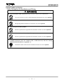
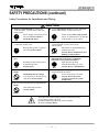
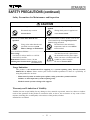
6F8A0870 ELECTROMAGNETIC FLOWMETER MODEL DETECTOR LF414 INSTRUCTION MANUAL NOTES Before using the equipment, please read this manual carefully and understand the contents, and then use the equipment correctly. • NEVER attempt to operate the equipment in any ways that are not described in this instruction manual. • After reading this manual, store it with care in a place where it can be referred to whenever needed. • Please be sure that this manual is delivered to the personnel who will use this product. 6F8A0870 NOTICE We thank you very much for your purchase of our LF414 series electromagnetic flowmeter detector. Integral type LF414/LF600F, LF414/LF610F Separate type detector LF414 This instruction manual describes the notes on using an electromagnetic flowmeter detector, installation, configuration and maintenance. It is intended for the personnel in charge of installation, operation and maintenance. To use this product properly and safely, read this manual (6F8A0870) carefully before using this product. After reading this manual, store it in a place where it can be referred to whenever needed. This manual uses the following markers to identify the integral type or separate type when it describes items specific to the integrated type or separate type. Items without this marker are common items to the integral type and separate type. Integral type LF414/LF600F, LF414/LF610F: Integral Separate type detector LF414: Separate Toshiba LF414 electromagnetic flowmeter detectors can be used in combination with various types of electromagnetic flowmeter converters (LF600F, LF610F, LF602F and LF612F). For the notes on usage, connecting, wiring, installation, configuration and maintenance of the combined converter, check the model number of the combined converter and read the instruction manual of the relevant converter. About Safety Precautions Read the Safety Precautions described at the front carefully and understand the contents before using this product. The “Safely symbols” used in the “Safety Precautions” are shown in a location such as in the margin to the left of the corresponding commentary in the main text. NOTES 1. The reproduction of the contents of this Manual in any form, whether wholly or in part, is not permitted without explicit prior consent and approval. 2. The information contained in this Manual is subject to change or review without prior notice. 3. Be sure to follow all safety, operating and handling precautions described in this Manual and the regulations in force in the country in which this product is to be used. 5th Edition First Edition Apr, 2008 September, 2005 - 1 - 6F8A0870 SAFETY PRECAUTIONS Safety signs and labels affixed to the product and/or described in this manual give important information for using the product safely. They help prevent damage to property and obviate hazards for persons using the product. Make yourself familiar with signal words and symbols used for safety signs and labels. Then read the safety precautions that follow to prevent an accident involving personal injury, death or damage to property. Explanation of signal words The signal word or words are used to designate a degree or level of hazard seriousness. The signal words used for the product described in this manual are WARNING and CAUTION. WARNING CAUTION Indicates a potentially hazardous situation which, if not avoided, could result in death or serious injury. Indicates a potentially hazardous situation which, if not avoided, may result in minor to moderate injuries or in property damage. Safety symbols The following symbols are used in safety signs and labels affixed to a product and/or in the manual for giving safety instructions. Indicates an action that is prohibited. Simply DON’T do this action. The prohibited action is indicated by a picture or text inside or next to the circle Indicates an action that is mandatory. DO this action. The mandatory action is indicated by a picture or text inside or next to the circle. Indicates a potential hazard. The potentially hazardous situation is indicated by a picture or text inside or next to the triangle. - 2 - 6F8A0870 SAFETY PRECAUTIONS Safety Precautions for Installation and Wiring WARNING Do not disconnect while circuit is live unless location is known to be nonhazardous. Live part of electric circuit or a high temperature department can cause explosion. DON’T Do not modify or disassemble the enclosure. Strength degradation and defects of enclosure can cause explosion. DON’T Do not use parts of other products. Protective performance degradation for hazardous location can cause explosion. DON’T Do not touch live circuits until assembly of all components is not over. Protective performance degradation for hazardous location can cause explosion. DON’T Install per the National Electrical Code for the US (NEC, ANSI/NFPA 70) and the Canadian Electrical code for Canada (CEC, CAN/CSA-C22.1) and the drawing 3S8A2532,3S8A2533 (Refer to Appendix 1.). Unsuitable conduit connections for hazardous location can cause explosion. DO - 3 - 6F8A0870 SAFETY PRECAUTIONS (continued) Safety Precautions for Installation and Wiring CAUTION Install a switch and fuse to isolate the LF414/LF600F, LF610F and LF414 from mains power. Power supply from mains power can cause electric shock or circuit break-down. Use an appropriate device to carry and install the LF414/LF600F, LF610F and LF414. Turn off mains power before conducting wiring work. Do not modify or disassemble the LF414/LF600F, LF610F and LF414 unnecessarily. Modifying or disassembling this product can cause electric shock, malfunction of or DON’T damage to this product. Ground the LF414/LF600F, LF610Fand LF414 independently from power equipment. (100 ohm or less ground resistance) Operating this product without grounding can cause electric shock or malfunction. DO Wiring while power is applied can cause electric shock. DO Turn off mains power before working on pipes. DO Working on pipes while power is applied can cause electric shock. DO If this product falls to the ground, injury, or malfunction of or damage to the product, can be caused. DO Do not conduct wiring work with bare hands. Remaining electric charge even if power is turned off can still cause electric shock. Use crimped terminal lugs for the terminal board and GND terminal. Loose connections can cause electric shock, fire from excessive current or system DO malfunction. DON’T Do not work on piping and wiring with wet hands. Wet hands may result in electric shock. DON’T The label shown left is placed near the terminal board for power supply on the converter. (A black border and symbol on yellow triangle) Be alert to electric shock. - 4 - 6F8A0870 SAFETY PRECAUTIONS (continued) Safety Precautions for Maintenance and Inspection CAUTION Do not conduct wiring work with wet hands. Wet hands may result in electric shock. Do not conduct wiring work when power is applied. Wiring while power is applied can cause electric shock. DON’T DON’T Do not use a fuse other than the one specified. DON’T Using a fuse other than the one specified can cause system failure, damage or malfunction. Do not touch the LF414/LF600F, LF610F and LF414 main body when high temperature fluid is being measured. The fluid raises the main body temperature and can cause burns when touched. DON’T Use a rated fuse as follows: Fuse rating: • 1A/250V for 100 to 240Vac or 110Vdc • 2A/150V for 24 Vdc Dimensions: Diameter 5 mm × 20 mm Melting time characteristic: Medium Acting (Normal blow) The label shown left is placed near the terminal board for power input of the converter. (A black border and symbol on yellow triangle) Be alert to electric shock. Usage limitation This product is not manufactured for applying to a system requiring safety directly involved human life as follows. Please contact your nearest Toshiba reprehensive if there is a possibility of using this product for such use. - Main control systems of nuclear power plants, safety protection systems in nuclear facilities or other important systems requiring safety - Medical control systems relating to life support Warranty and Limitation of Liability Toshiba does not accept liability for any damage or loss, material or personal, caused as a direct or indirect result of the operation of this product in connection with, or due to, the occurrence of any event of force majeure (including fire or earthquake) or the misuse of this product, whether intentional or accidental. - 5 - 6F8A0870 Handling Precautions To obtain the optimum performance from the LF600F, LF610F, LF602F and LF612F converter for years of continuous operation, observe the following precautions. (1) Do not store or install the flowmeter in: ・Places where there is direct sunlight. ・Places where there is snow and ice Infrared switches may not function correctly. ・Places where excessive vibration or mechanical shock occurs. ・Places where high temperature or high humidity conditions obtain. ・Places where corrosive atmospheres exist. ・Places submerged under water. ・Places where there is a sloped floor. To put the flowmeter temporarily on the floor, place it carefully with something, such as a block, to support it so that the flowmeter will not topple over. ・Places where there is following factors. Factors to impede infrared switch to operate properly ・Intense light such as direct sunlight and reflected sunlight by window glass or metal plate ・Place where brightness changes suddenly such as ON/OFF of lighting ・Dense smoke or steam near the control panel ・Those attached on the control panel such as rain (dew drop), snow, ice, mud and oil, and haze due to their attachment ・Light reflecting object near the control panel, or reflecting object such as metal plate placed opposing to the control panel When any of above factors is considered, take a measure for the proper operation of infrared switch such as to place a cover or to secure a space for at least a person to stand in front of the control panel. When unable to avoid above factors, operate the EMF converter removing the factor by covering the control panel by hand so that light does not shine on it, by cleaning those attached on the control panel, or by standing in-between the reflecting object and the control panel to block the light. (2) Wire cables correctly and securely. Be sure to ground at the converter side (grounding resistance 100Ω or less). Avoid a common ground used with other equipment where earth current may flow. An independent ground is preferable (3) Select cable paths away from electrical equipment (motors, transformers, or radio transmitters), which causes electromagnetic or electrostatic interference. (4) The apparatus should not be provided with the cable connections. Please prepare yourself for the cable connections which could be used in Division2 hazardous locations. The cable lead-in section must be tightened securely to keep air tightness. - 6 - 6F8A0870 Handling Precautions (continued) (5) If the inside of the converter and detector's terminal box are wetted or humidified, it may cause insulation deterioration, which can result in fault or noise occurrence. So do not conduct wiring in the open air on rainy days. Also, be careful not to wet down the converter and detector's terminal box even in the case of indoor wiring, and complete wiring work in a short period of time. (6) Observe the following precautions when you open the converter housing cover: • Do not open the cover in the open air unprotected against rain or wind. This can cause electric shock or cause damage to the flowmeter electronics. • Do not open the cover under high ambient temperature or high humidity conditions or in corrosive atmospheres. This can cause deterioration of system accuracy or cause damage to the flowmeter electronics. (7) Since a varistor is built in converter, do not conduct a withstand voltage test for the converter. In addition, the voltage for checking the insulation of the converter must be 250VDC or lower. (8) This product may cause interference to radio and television sets if they are used near the installation site. Use metal conduits etc. for cables to prevent this interference. (9) Radio transmitters such as transceivers or cellular phones may cause interference to the flowmeter if they are used near the installation site. Observe the following precautions when using them: • Close a transmitter cover before using a transceiver. • Do not use a transceiver whose output power is more than 5 W. • Move the antenna of a transceiver or a cellular phone at least 50 cm away from the flowmeter and signal cables when using it. • Do not use a radio transmitter or a cellular phone near the flowmeter while it is operating online. The transmitter or cellular phone’s output impulse noise may interfere with the flowmeter. • Do not install a radio transmitter antenna near the flowmeter and signal cables. (10) For reasons of flowmeter failure, inappropriate parameters, unsuitable cable connections or poor installation conditions, the flowmeter may not operate properly. To prevent any of these problems causing a system failure, it is recommended that you have preventive measures designed and installed on the flowmeter signal receiving side. (11) For installation and connection of the converter, check the model number of converter and read the instruction manual of the relevant converter. * We assume no responsibility for nonconformity caused by violation of precautions described in this manual or used in violation of the installation method and the operation method stipulated in a relevant ordinance or other regulations. - 7 - 6F8A0870 Table of Contents SAFETY PRECAUTIONS ····················································································· 2 Handling Precautions ······························································································ 6 1. Product Inspection and Storage ······································································ 9 1.1 Product Inspection ······················································································· 9 1.2 Storage ········································································································ 9 2. Overview ·········································································································· 10 3. Names of Parts ································································································· 11 4. Installation ······································································································· 20 4.1 Notes on Selecting the Installation Location ············································· 21 4.2 Mounting Procedure···················································································· 21 4.3 Piping Connections ··················································································· 25 4.4 Grounding ································································································· 28 5. Wiring ·············································································································· 30 5.1 Cables ········································································································ 31 5.2 External Device Connections and Grounding ············································ 32 5.3 Notes on Wiring ······················································································ 32 5.4 Wiring ····································································································· 33 6. Operation ········································································································· 36 7. Maintenance and Troubleshooting ································································· 37 7.1 Maintenance ······························································································ 38 7.2 Troubleshooting ························································································ 39 8. Principle of Operation ··················································································· 42 9. Specifications ·································································································· 43 9.1 Flowmeter Specifications ··········································································· 43 9.2 Type Specification Code ············································································ 46 10. Outline Dimensions ························································································· 48 Appendix 1 (A system block diagram) ································································· 52 - 8 - 6F8A0870 1. Product Inspection and Storage 1.1 Product Inspection LF414 series electromagnetic flowmeter is shipped in a cardboard container filled with shock-absorbing materials. Open the package carefully and check as follows: Make sure the following items are included in the package. For the integral type (when a converter and detector are united) Integral Electromagnetic flowmeter main unit --------------------------------- 1 unit Instruction manual---------------- One each for the converter and detector For the separate type (when a converter and detector are separated) Electromagnetic flowmeter converter---------------------------------- 1 unit Electromagnetic flowmeter detector ----------------------------------- 1 unit Separate Instruction manual---------------Once each for the converter and detector Inspect the flowmeter for indications of damage that may have occurred during shipment. Make sure the type and specifications of the flowmeter are in accordance with the ordered specifications. If you cannot find the items listed above or any problem exists, contact your nearest Toshiba representative. 1.2 Strage To store the electromagnetic flowmeter after opening the package, select a storing place as follows and keep it under the conditions described below: CAUTION (1) Avoid places where there is direct sunlight, rain or wind. (2) Store the product in a well-ventilated place. Avoid places of extremely high humidity or extremely high or low temperature. The following environment is recommended: • Humidity range: 10 to 90% RH (no condensation) • Storage temperature: –25 to +65° C (3) Avoid places where vibrations or mechanical shock occur. (4) If the cover of the converter is left open while being stored, gradual deterioration of circuit isolation can be caused. Therefore don’t open the cover until it is connected with wires. (5) To put the flowmeter temporarily on the floor, place it carefully with something, such as block orstopper, to support it so that the flowmeter will not topple over. - 9 - 6F8A0870 2. Overview The LF414/LF600F, LF414/LF610F and LF414 electromagnetic flowmeter can be use in the following hazardous (classified) locations. ClassⅠ, Division 2, Groups A, B, C and D, ClassⅡ, Division 2, Groups E, F and G ClassⅢ This product is a converter used for electromagnetic flowmeters that measure the volumetric flow rate of conductive fluid using Faraday's law of electromagnetic induction. You can bring out the functions of the converter when you place it in the converter housing you prepare and use it in combination with a fluid rate measurement detector. The converter sends out a signal to drive the detector excitation coil, which generates a magnetic field inside the detector. The converter receives the signal electromotive force obtained by the detector. The signal electromotive force is proportional to the generated flow rate in the fluid using Faraday's law of electromagnetic induction. After carrying out its operation, the converter converts the signal electromotive force to an analog signal output and displays the status, as a flow rate value. Features With a linear relationship between the flow rate and output signal, the electromagnetic flowmeter is used as an easy-to-read indicator. In addition to this feature, it has the following outstanding features: (1) Wide flow velocity range setting, such as a flow velocity range of 0~0.1 and 0~10m/s, is achieved. (2) The unique Noise Sentry filter circuit enables you to obtain stable output automatically. (3) Full graphic LCD that enables display of a large amount of information With a large amount of a maximum of 14 characters x 8 lines, you can easily set up various displays including bar graphs and alarm indications. The backlight display allows you to read the indicator easily. (4) Use of infrared switches Use of infrared switches allows you to perform various operations, without opening the converter housing cover. (5) Intelligent functions The widely used HART protocol communications system is used as a standard feature. This product supports PROFIBUS*2 communication (optionally available). * 1 HART protocol: “HART” stands for Highway Addressable Remote Transducer and is a communication protocol recommended by HCF (HART communication Foundation) for industrial sensors. * 2 PROFIBUS:PROFIBUS, which stands for PROCESS FIELDBUS, is a field bus that is approved by international standard IEC61158. The electromagnetic flowmeter supports PRFIBUS PA for process automation. - 10 - 6F8A0870 3. Names of Parts IMPORTANT The apparatus should not be provided with the cable connections. Please prepare yourself for the cable connections which could be used in Division2 hazardos l i 3.1 Appearance 3.1.1 Appearance of LF414/LF600F, LF414/LF610F Integral (1) Meter size of 1/2 inch (15mm) For the detail of the converter, check the LF600F, LF610F converter's instruction manual. Terminal block cover Ground terminal for converter Flow direction arrow Detector Ground terminal for detector Grounding ring Window for electrode Figure 3.1.1 Appearance of LF414/LF600F, LF610F Meter size 1/2inch(15mm) - 11 - 6F8A0870 (2) Meter size of 1inch (25mm) For the detail of the converter, check the LF600F, LF610F converter's instruction manual. Terminal block cover Ground terminal for converter Flow direction arrow Detector Ground terminal for detector Grounding ring Window for electrode Figure 3.1.2 Appearance of LF414/LF600F, LF610F Meter size 1 inch(25mm) - 12 - 6F8A0870 (3) Meter size of 1 1/2 to 4 inch (40 to 100mm) For the detail of the converter, check the LF600F , LF610F converter's instruction manual. Terminal block cover Ground terminal for converter Flow direction arrow Ground terminal for detector Detector Grounding ring Figure 3.1.3 Appearance of LF414/LF600F, LF610F Meter size 1 1/2 to 4 inch (40 to 100mm) - 13 - 6F8A0870 (4) Meter size of 6 and 8 inch (150 and 200mm) For the detail of the converter, check the LF600F, LF610F converter's instruction manual. Terminal block cover Flow direction arrow Ground terminal for converter Ground terminal for detector Grounding ring Detector Figure 3.1.1 Appearance of LF414/LF600F, LF610F Meter size 6 and 8 inch(150 and 200mm) - 14 - Lifting Lugs *Only 8 inch (200mm) provided. 6F8A0870 3.1.2 Appearance of LF414 Separate (1) Meter size of 1/2 inch (15mm) Excitation cable 3/4 - 14 NPT Terminal Box Cover Signal cable 3/4 - 14 NPT Terminal Box Flow direction arrow Detector Ground terminal for detector Grounding ring Window for electrode Figure 3.1.2 Appearance of LF414 Meter size 1/2inch(15mm) - 15 - 6F8A0870 (2) Meter size of 1inch (25mm) for Excitation cable 3/4 - 14 NPT for Signal cable 3/4 - 14 NPT Terminal Box Cover Terminal Box Flow direction arrow Detector Ground terminal for detector Grounding ring Window for electrode Figure 3.1.2 Appearance of LF414 Meter size 1 inch(25mm) - 16 - 6F8A0870 (3) Meter size of 1 1/2 to 4 inch (40 to 100mm) Excitation cable 3/4 - 14 NPT Signal cable 3/4 - 14 NPT Terminal Box Cover Terminal Box Flow direction arrow Detector Ground terminal for detector Grounding ring Figure 3.1.3 Appearance of LF414 Meter size 1 1/2 to 4 inch (40 to 100mm) - 17 - 6F8A0870 (4) Meter size of 6 and 8 inch (150 and 200mm) Excitation cable 3/4 - 14 NPT Signal cable 3/4 - 14 NPT Terminal Box Cover Terminal Box Flow direction arrow 矢印銘板 Ground terminal for detector Grounding ring Detector Figure 3.1.4 Appearance of LF414 Meter size 6 and 8 inch(150 and 200mm) - 18 - Lifting lugs *Only 8 inch (200mm) provided. 6F8A0870 3.2 Construction of the terminal blocks 3.2.1 Terminal Block Construction of LF414/LF600F, LF414/LF610F Type For details of the converter, check the LF600F, LF610Fconverter's instruction manual. Integral 3.2.2 Terminal Block Construction of LF414 Type Separate Signal cable terminal Figure 3.2.2 Excitation cable terminal Terminal Block of LF414 - 19 - 6F8A0870 4. Installation Safety Precautions for Installation WARNING Do not live active circuits under environment of explosive atmospheres. Live part of electric circuit or a high temperature department can cause explosion. DON’T Do not use parts of other products. Protective performance degradation for hazardous location can cause explosion. DON’T Do not active live circuits While assembly of all components is not over. Protective performance degradation for hazardous location can cause explosion. DON’T Install per the National Electrical Code for the US (NEC, ANSI/NFPA 70) and the Canadian Electrical code for Canada (CEC, CAN/CSA-C22.1) and the drawing 3S8A2532,3S8A2533 (Refer to Appendix 1.). Unsuitable conduit connections for hazardous location can cause explosion. DO CAUTION Ground the LF414/LF600F, LF610F and LF414 independently from power equipment. (100 ohm or less ground resistance) DO Operating this product without grounding can cause electric shock or malfunction. Install a switch and fuse to isolate the LF414/LF600F, LF610F and LF414 from mains power. DO Power supply from mains power can cause electric shock or circuit break-down. Use an appropriate device to carry and install the LF414/LF600F, LF610F and LF414 . DO Do not modify or disassemble the LF414/LF600F, LF610F and LF414 unnecessarily. Modifying or disassembling this product can cause electric shock, malfunction or damage to this product. DON’T Do not work on piping and wiring with wet hands. Wet hands may result in electric shock The label shown left is placed near the terminal board for power supply to the converter. Be alert to electric shock DON’T - If his product falls to the ground, injury, or malfunction of or damage to the product, can be caused. 20 - 6F8A0870 4.1 Notes on Selecting the Installation Location 1. 2. 3. Avoid places within the immediate proximity of equipment producing electrical interference (such as motors, transformers, radio transmitters, electrolytic cells, or other equipment causing electromagnetic or electrostatic interference). Avoid places where excessive pipe vibration occurs. Avoid places where fluid is pumped in a pulsating manner. Avoid places where there is direct sunlight. If this is unavoidable, use an appropriate shade Avoid places where corrosive atmospheres or high humidity conditions occur. Avoid places where there may be limited access such as pipes installed next to high ceilings or constricted areas where clearance for installation or maintenance work is not provided. 7. Design piping so that the detector pipe is always filled with fluid, whether the fluid is flowing or not. 8. The detector has no adjustable piping mechanism. Install an adjustable short pipe where needed. 9. Chemical injections should be conducted on the downstream side of the flowmeter. 10. The maximum length of the cable that connects the detector and converter is 300m. Select the converter installation location so that the distance between the detector and converter does not exceed Separate 300m. 4. 5. 6. 4.2 Mounting Procedure 4.2.1 Pipe checks (1)Before installing pipes, check for any leaning, misplacement or eccentricity as illustrated in Figure 4.1. An attempt to unreasonably connect pipes that are inclined may lead to a detector breakdown or fluid leakage. Connecting pipes in an eccentric state may also cause wear and tear of linings and grounding rings, as well as measurement errors. Before installing pipes, make sure to flush the interior of the pipes to remove deposited material.. Eccentricity Inclination (a) Pipe leaning Figure 4.1 (b) Pipe axis misplacement (or eccentricity) Pipe leaning and axis misplacement - 21 - 6F8A0870 (2) Preventing an Empty Pipe Condition Fix the relevant pipes installed on both sides of the detector by attaching fittings, etc. to support the pipe. By supporting the pipes, not only the pipe vibration is reduced but also the damage to the pipes by the electromagnetic flowmeter's weight and the fluid mass (see Figures 4.2 and 4.3). Pipe support fittings Pipe support fittings Figure 4.2 Example of Pipe Fixing Procedure Figure 4.3 Model Diagram of Unsupported Pipes - 22 - 6F8A0870 4.2.2 Installation Procedure To mount the LF414, place it between the upstream and downstream pipe flanges and tighten it with flange bolts and nuts. See Figure 4.4 and follow the procedure below: 1. 2. 3. 4. 5. 6. Insert two lower mounting bolts through the clearance holes in the upstream (or downstream) pipe flange. Install a packing next to the upstream (or downstream) flange face and the other packing next to the downstream (or upstream) pipe flange. The two mounting bolts can now be guided through the clearance holes in the downstream packing and flange. Place the LF414 flowmeter detector between the two flange packings, with the flowmeter detector body above the two bolts. The flowmeter must be oriented in accordance with the flow direction arrow. Install the two upper mounting bolts through the clearance holes in the upstream and downstream packings and flanges. Then install the remaining mounting bolts depending on the flange pattern used. Thread nuts on both ends of the 4 (or more) mounting bolts, finger tight. (See Table 4.1 Bolt length and tightening torque) While centering the flowmeter with the longitudinal axis of the pipeline, tighten the nuts with a wrench diagonally across in even increments. (See Table 4.1 Bolt length and tightening torque) Note that the flowmeter detector pipe axis must be aligned with the pipeline axis on both upstream and downstream sides. This is essential to have stable characteristics of flow measurement (especially for flowmeters with meter sizes of 50 mm or less). IMPORTANT When high-temperature fluid is being measured, radiant heat from the detector pipe surface and adjoining pipes may cause the ambient temperature of the converter to go above 60 °C. If the ambient temperature goes above 60° C, try to lower the temperature by measures such as wrapping heat-insulating materials over the detector pipe and adjoining pipes. Figure 4.4 LF414 flowmeter detector piping connections - 23 - 6F8A0870 Table 4.1 Bolt length and Nut tightening torque Meter size ANSI class 150 ANSI class 300 Through Bolts Through Bolts Tightening Tightening torque torque Dia- Length DiaLength P.C.S P.C.S [N・m] [N・m] meter [mm] meter [mm] 15mm 1/2” 25mm 1” 4 4 1/2” 1/2” 150 170 12 to 15 21 to 26 4 4 1/2” 5/8” 155 180 25 to 31 53 to 66 40mm 1 1/2” 4 1/2” 195 32 to 40 4 3/4” 215 96 to 120 50mm 2” 4 5/8” 215 52 to 65 8 5/8” 220 52 to 65 80mm 3” 4 5/8” 225 71 to 88 8 3/4” 240 85 to 106 100mm 4” 8 5/8” 235 52 to 65 8 3/4” 255 125 to 156 150mm 6” 8 3/4” 355 104 to 130 12 3/4” 375 138 to 173 200mm 8” 8 3/4” 430 146 to 183 12 7/8” 460 227 to 284 Meter size 15mm 25mm 40mm 50mm 80mm 100mm 150mm 200mm 200mm (DIN/BS 16) DIN/BS 10, DIN/BS 16 Through Bolts Tightening torque Dia- Length P.C.S [N・m] meter [mm] 4 4 4 4 8 8 8 16 to 19 27 to 34 58 to 72 78 to 98 54 to 67 79 to 99 164 to 205 8 M12 150 M12 165 M16 190 M16 205 M16 210 M16 220 M20 340 (DIN/BS 10) M20 410 12 M20 156 to 195 410 146 to 183 - 24 JIS 10K Through Bolts P.C.S Diameter Length [mm] Tightening torque [N・m] 4 4 4 4 8 8 8 M12 M16 M16 M16 M16 M16 M20 150 170 190 200 210 215 340 10 to 13 22 to 28 32 to 40 43 to 53 27 to 34 37 to 46 70 to 88 12 M20 410 60 to 75 - 6F8A0870 4.3 Piping Connections (1a) Ideal Upstream Straight Pipe Length Installation Requirements If various joints are used upstream of the detector outlet, the straight pipe length as shown in Table 4.2 is required. Table 4.2 Required straight pipe length on the upstream side L=5D L=10D (5) Other valves (not fully opened) (1) 90°bent L L (2) Tee L (3) Diffuser L (4) Fully opened sluice valve L L: Required straight pipe length—straight pipe length plus half length of the detector. D: Nominal bore size (diameter) NOTES The length of a reducer, if connected, can be counted as a part of the straight pipe length. No straight pipe length is needed on the downstream side. If a butterfly valve is installed downstream of the detector, do not let the valve plate protrude into the pipe of the detector (1b) Optional “Mount Anywhere” Installation Mount-Anywhere Technology: With Toshiba’s unique, patented magnetic field distribution technology, the meter is highly immune to upstream flow disturbances. A minimum of 1D (diameter) length of upstream straight pipe from the flange is required to maintain the performance specification. NOTE The test results were obtained and demonstrated at Toshiba’s flow calibration facility, Fuchu Japan. - 25 - 6F8A0870 (2) Pipe Orientation The detector may be installed in horizontal, vertical or sloping pipe runs as shown in Figure 4.5. However, except for horizontal installation, fluid should flow from lower to upper directions. If no air bubble, vertical down flow application are acceptable under pressured piping conditions. See Figure 4.5. Flow direction (b) Detector (a) Horizontal pipe installation (b) Vertical pipe installation (c) Sloping pipe installation (c) (a) Ground surface Figure 4.5 Detector Piping Orientation The electrodes should be positioned horizontally relative to the ground surface in any piping installation. See Figure 4.6. Electrodes A Detector A' Cross-section A - A' Ground surface Figure 4.6 Installation position of the detector - 26 - 6F8A0870 (3) Flow Direction Install the detector in accordance with the flow direction arrow on the detector. See Figure 4.7. Flow direction arrow Figure 4.7 Flow direction arrow on the detector (4) Preventing an Empty Pipe Condition Design an upright pipe run (Figure 4.8) or sufficient head pressure (Fig. 4.9) at the downstream detector outlet if there is a possibility of the detector pipe becoming emptied. Vertical pipe run Detector Figure 4.8 Detector with an upright pipe run at downstream outlet Detector Figure 4.9 Detector with sufficient head pressure at downstream outlet - 27 - 6F8A0870 4.4 Grounding CAUTION Do not wire cables and replace parts when power is supplied. DON’T Do not work on piping and wiring with wet hands. Wet hands may result in electric shock. Wiring work and replacing parts in the power-on state may cause electric shock. DON’T (1) Grounding of the LF414/LF600F, LF414/LF610F type Integral Ground as shown in Figure 4.10. Make the grounding wire as short as possible. Use grounding wire material of IV wire 5.5mm2 or more. Do not share a grounding wire with other instruments where grounding current may flow. (An independent grounding is preferable.) Piping of non-conductive material Example: Resin or metal piping whose inside is resin-lined, etc. Conductive material pipe Example: Metal, etc. Grounding terminal Grounding wire • If the piping material is non-conductive, perform grounding (grounding resistance 100Ω or less). • If the piping material is conductive, connect the grounding wires to the both ends of the piping flange. Figure 4.10 Grounding the LF414/LF600F, LF414/LF610F Type - 28 - grounding resistance 100Ω or less 6F8A0870 (2) Grounding of the LF414 type Separate Ground the external grounding terminal of the detector and the FG terminal of the converter (or external grounding terminal of the converter) securely (grounding resistance 100Ω or lower). Use grounding wire material of IV wire 5.5mm2 or more. Do not share a grounding wire with other instruments where grounding current may flow. (An independent grounding is preferable.) If it is difficult to perform grounding work at the detector side because of a pit installation or other reasons, use a 3-core cable for the excitation cable and connect the E terminal of the detector to the E terminal of the converter. (The E terminal of the converter is internally connected with the FG terminal and the converter case.) Converter terminal block A B G E X Y Converter terminal block FG A B G E X Y FG Shield twisted Shield twisted Grounding terminal Grounding terminal (100 ohm or less ground resistance) (100 ohm or less ground resistance) Input signal cable Input signal cable Excitation cable Excitation cable Shield twisted Shield twisted Grounding terminal Grounding terminal G A B E X Y G Converter terminal block E A B (100 ohm or less ground resistance) Figure 4.11 (a) Wiring between Detector and Converter (For grounding the detector, see Figure 4.12 below.) Conductive material piping Example: Metal, etc. X Y Converter terminal block Figure 4.11 (b) Wiring between Detector and Converter (when grounidng of the detector is difficut) Non-conductive material piping Example: Resin product or metal piping whose inside is resin lined Grounding terminal Grounding terminal Grounding wire Grounding wire (100 ohm or less ground resistance) • If the piping material is conductive, connect the grounding wires to the both ends of the piping flange. Figure 4.12 • If the piping material is non-conductive, perform grounding resistance 100Ω or less. Grounding the LF414 Type Detector - 29 - 6F8A0870 5.Wiring Safety Precautions for Wiring WARNING DO NOT DISCONNECT WHILE CIRCUIT IS LIVE UNLESS LOCATION IS KNOWN TO BE NONHAZARDOUS. Live part of electric circuit or a high temperature department can cause explosion. DON’T Do not active live circuits While assembly of all components is not over. Protective performance degradation for hazardous location can cause explosion. DON’T Install per the National Electrical Code for the US (NEC, ANSI/NFPA 70) and the Canadian Electrical code for Canada (CEC, CAN/CSA-C22.1) and the drawing 3S8A2532,3S8A2533 (Refer to Appendix 1.). Unsuitable conduit connections for hazardous location can cause explosion. DO - 30 - 6F8A0870 CAUTION Install a switch and fuse to isolate the LF414/LF600F, LF610F and LF414 from mains power. Power supply from mains power can cause electric shock or circuit break-down. Turn off mains power before conducting wiring work. Do not work on piping and wiring with wet hands. Ground the LF600F, LF610 independently from power equipment. (100 ohm or less ground resistance) Operating this product without grounding can cause electric shock or malfunction. DO Wet hands may result in electric shock DON’T DO DO Do not conduct wiring work with bare hands. DON’T Wiring while power is applied can cause electric shock. Remaining electric charge even if power is turned off can still cause electric shock. For the power supply wiring and grounding wiring, use crimping terminals with insulated sleeve. There is a risk of electric shock due to drop-off or loosing, and a risk of fire and equipment trouble due to heat generation. DO Do not modify or disassemble the LF600F, LF610F, LF602F and LF612F unnecessarily. Modifying or disassembling this product can cause electric shock, malfunction of or damage to this DON’T product. The label shown left is placed near the power supply terminal on the converter. Be alert to electric shock. Flowmeter accuracy may be affected by the way wiring is executed. Proceed with correct wiring taking the precautions in following pages. - 31 - 6F8A0870 Notes on wiring CAUTION (1) Select the cable runs away from electrical equipment (motors, transformers, or radio transmitters) which causes electromagnetic or electrostatic interference. (2) Deterioration of flowmeter circuit insulation occurs if the converter interior or cable ends get wet or humidified. This in turn causes malfunction of flowmeter or noise problems. Avoid a rainy day if the flowmeter is to be installed outdoors. Even indoors, prevent water from splashing over the flowmeter. Try to finish the wiring as quickly as possible (3) The converter has an arrestor installed inside. Therefore, do not conduct a withstand voltage test for the converter. To check the insulation of the converter, use a voltage of 250Vdc or less. (4) After wiring, be sure to install the terminal block protection cover. (5) Because the excitation cable and flow rate signal cable transmit very delicate signals, pass each of them separately through a thick steel conduit tube, keep them away from the large current wiring as far as possible, and do not install them in parallel. Separate 5.1 Cables Use the kind of cables shown in Table 5.1 to wire the converter. Table 5.1 Installation Cables Name Cable name Nominal cross-section al area Finished outer diameter Power cable 3-core vinyl sheathed cable or 2-core vinyl sheathed cable 2 mm² 11~13mm Output signal cable The number of conductors the cable contains differs depending on the CVV-S JIS -258-C or specification of the output signal cable. Use a shielded cable of finished outer diameter 11 to 13mm and equivalent nominal cross-sectional area 1.25mm2. Flow rate signal cable Separate Excitation cable 2-core shielded chloroprene cabtyre cable ( Rubber covered cable ) 11~13mm 2PNCT-S JIS C 3327 or equivalent 2 mm2 1.25 m2 11~13mm 2PNCT JIS C 3327 or equivalent Separate 32 CVV JIS C 3401 or equivalent 0.75 mm2 3-core chloroprene cabtyre cable ( Rubber covered cable ) - Description - 6F8A0870 5.2 External Device Connections and Grounding For the notes on connecting, wiring and installation of the combined converter, check the model number of the combined converter and read the instruction manual of the relevant converter. 5.3 Notes on Wiring 5.3.1 Notes on Instrumentation-Converter Wiring • • • To avoid 2-point grounding, ground the shield of output cable basically at the receiving side. Use a grounding wire of IV wire 5.5mm2 or more. The size of the external grounding terminal screws is M4. Do not share a grounding wire with other instruments where grounding current may flow. (An independent grounding is preferable.) Power cable When a 3-core cable is used: Ground with the FG terminal. When a 2-core cable is used: Use an external grounding terminal and make the cable as short as possible. 5.3.2 Notes on Wiring of the Separate type (LF414) Separate • • • • • The detector is shipped with a flow rate signal cable and excitation cable. Be sure to use those cables coming with the detector. Note: When the cable length exceeds 300m, cables may not be supplied. Check whether the cable is supplied with the specs. The allowable cable length between the detector and converter varies depending on the conductivity of the operating fluid. Refer to the instruction manual of the combined detector. When connecting with the detector, wire the cables in the order of the excitation cable and flow rate signal cable. Because the input cables transmit very delicate signals, pass the excitation cable and input signal cable separately through a thick steel conduit tube, keep them away from the large current wiring as far as possible, and do not install them in parallel. When replacing the flow rate signal cable and excitation cable, also refer to the instruction manual of the relevant detector. Order the detector terminal box cover packing from Toshiba. - 33 - 6F8A0870 5.4 Wiring 5.4.1 Terminal Treatment of Cables Follow the procedures below to treat the terminals (at the converter side) of various cables and install the cables to the terminal block. Use appropriate cables based on the description in Section 5.1 "Cables." Crimp a round type insulated crimp-type terminal to the end of the cables. (1) Power cable, current output cable, digital I/O cables The necessary cables should be ordered from the person responsible for the installation. Strip the sheath of each conductor as shown in Figure 5.1 and attach a crimping terminal with insulated sleeve to it. The size of the crimping terminal is as follows: Integral type LF600F, LF610F: M4 Separate type LF602F, LF612F: M3.5 • Connect the power cable to terminal blocks L1 and L2. • Connect the current output cable to terminal blocks + and -. • Connect the digital I/O cable to terminal blocks D1, D01, D02 and COM, as required. Crimping terminal LF600F, LF610F type: M4 LF602F, LF612F type: M3.5 25~45mm Figure 5.1 Terminal Treatment of Power Cable, Current Output Cable and Digital I/O cable (2) Excitation cable Separate Strip the sheath from the end of each conductor as shown in Figure 5.2, attach an M3.5 crimping terminal with insulated sleeve, and connect it to the terminal blocks X and Y. Connect the red conductor to terminal block E. M3.5 crimping terminal X Black E Red Y White 25~45mm Figure 5.2 Terminal Treatment of Excitation Cable - 34 - 6F8A0870 (3) Connecting the input signal cable Separate Strip the sheath from the end of each conductor of a 2-core individually shielded cable as shown in Figure 5.4. Twist those shields and cover them with a thermal contraction tube or vinyl tube not to make contact with the case or core wires. Then attach an M3.5 crimping terminal with insulated sleeve as shown in Figure 5.3. Connect a crimping terminal to the A and B terminals on the terminal block and connect to each G terminal of the detector and converter. M3.5 crimping terminal Thermal contraction tube or vinyl tube A Black G Shield B White 25~45mm Figure 5.3 Terminal Treatment of Flow Rate Signal Cable ● Notes on signal cable shield processing work When stripping an external sheath, intermediate and insulated sheath, be careful not to scratch or cut the internal conductors and shield mesh. Do not disjoint the shield mesh but treat it as shown in Figure 5.9. a. Open the shield mesh with a pencil or the like. Coated wire b. Pull out the internal coated wires from the hole of the shielded mesh. Shield mesh c. Pull out all internal coated wires and extend the shield mesh wire. Figure 5.4 Treating the Signal Cable Shield Mesh - 35 - 6F8A0870 5.4.2 Cable Connection Connect and install the terminal-treated cables to the terminal block. *Connect the cables to the terminal block securely. A loose connection may cause incorrect measurement. After connecting a cable, try to pull it to check whether it has been connected securely. Referring to combined converter's manuals of "Connections and Grounding", connect each cable to the terminal block. Tighten the screws of the terminal block tightly to ensure a secure connection. A loose connection may cause incorrect measurement. After connecting a cable, try to pull it to see whether it has been connected securely. Phillips screwdriver * The appropriate torque for tightening the terminal board screw is 1.2 N.m. Terminal block Figure 5.5 Connecting a Cable to Terminal Block - 36 - 6F8A0870 6. Operation CAUTION Do not touch the terminal board when power is supplied. Touching the terminal board when power is supplied can cause electric shock. DON’T Do not touch the main body when high temperature fluid is being measured. The fluid raises the main body temperature and can cause burns. DON’T Preparatory check Follow the procedure described below to prepare before starting the flow measurement (described with regard to the entire flowmeter). System Check Check the items listed below Check the wiring between the converter and related instruments. Make sure all the bolts of connection flanges on which the flowmeter is mounted securely tightened. Make sure the direction of flow arrow is in accordance with actual flow. Make sure the flowmeter is grounded with 100 ohm or less ground resistance. Make sure the housing covers are securely tightened. Placing System On-Stream Let the fluid go through the detector pipe. (Note 1) When the detector is filled with the fluid, stop the fluid and keep it still in the detector pipe. Supplying Electric Power Make sure the power supply is as specified. Checking Converter Parameters Check the configuration parameter settings. Refer to combined converter's manual. Zero Adjustment Wait for 30 minutes to warm up the flowmeter. Then making sure the fluid holds still in the detector pipe, starts the zero adjustment. Refer to combined converter's manual. On-line measurement After checking the items and conducting the zero adjustment as listed above, let the fluid go through the detector pipe. Output (4–20 mA dc) directly proportional to the flow rate can be obtained. Note 1: If the detector pipe is not filled with the fluid to be measured, the flow rate will be indefinite and unable to be measured. Before using the flowmeter , be sure to fill the detector pipe the fluid to be measured. - 37 - 6F8A0870 7. Maintenance and Troubleshooting Safety precaution for Maintenance and Troubleshooting WARNING Do not disconnect while circuit is live unless location is known to be nonhazardous. Live part of electric circuit or a high temperature department can cause explosion. DON’T Do not modify or disassemble the enclosure. Strength degradation and defects of enclosure can cause explosion. DON’T Do not use parts of other products. Protective performance degradation for hazardous location can cause explosion. DON’T Do not live circuits While assembly of all components is not over. Protective performance degradation for hazardous location can cause explosion. DON’T Install per the National Electrical Code for the US (NEC, ANSI/NFPA 70) and the Canadian Electrical code for Canada (CEC, CAN/CSA-C22.1) and the drawing 3S8A2532,3S8A2533 (Refer to Appendix 1.). Unsuitable conduit connections for hazardous location can cause explosion. DO CAUTION Do not conduct wiring work when power is applied. DON’T Do not touch the LF414/LF600F, LF610F and LF414 main body when high temperature fluid is being measured. Wiring while power is applied can cause electric shock. - The fluid raises the main body temperature and can cause burns. DON’T 38 - 6F8A0870 7.1 Maintenance Cleaning Adhesion might be created in the detectore over a long period of time when used on certain materials. Try to confirm whether to cause the adhesion in the detector pipe when the phenomenon is seen, and and an abnormality (ex. decreasing indication, etc.) is confirmed. Please clean with a soft brush etc. and remove any unnecessary build up inside the meter. When using it in the line to which such a phenomenon occurs easily, it is recommended that the detector pipe be cleaned regularly. Use new gaskets when reinstalling the flowmeter detector in the pipeline. Mag-Prover Built-In Calibrator The converter LF60*F and LF61*F has a built-in reference signal calibration and verification circuit that allows you to re-verify the original magmeter flow lab calibration without the need for external devices. This reference signal can be used to check the zero and span of the converter for the purpose of instrumentation maintenance or periodical inspection. Refer to combined converter's manual. Operative life The operative life of this flowmeter is 10 years from the date of shipment. The life of the flowmeter differs depending on the environmental conditions and the way it was used. To extend the life of the flowmeter, inspect the flowmeter periodically and clean or replace components if necessary. Product disposal The electromagnetic flowmeter must be disposed of, according to the rules and regulations of your local government. Especially if you dispose of electrolytic capacitors to replace parts, have it done by an agency which is licensed to handle industry waste materials. Fuse The fuse can be taken out by unscrewing the cap of the fuse holder. Check that the fuse is not damaged. The fuse has to be replaced periodically. The recommended replacement period is 3 years. Integral Type of fuse used: Rating: Glass tube fuse , Medium Acting type (normal blow) 1 piece 1A/250 V for 100 to 240 Vac and 110Vdc power supply 2A/150V for 24Vdc power supply Dimensions: Diameter 5 mm × 20 mm Note: Use a fuse that complies with the Electrical Appliance and Material Safety Law. Check/Replacement of the display unit When characters displayed on the LCD display become thin or blots come out, please adjust the setting of LCD's display density. If the display is still not improved, the display unit comes to the end of its life. Please Integral replace the display unit with a new one. In order to use the display unit stably for a long time, it is preferable to replace it early. For inspection and replacement, please contact your nearest Toshiba representative. Power supply unit (also used for excitation board) Electronic components deteriorate faster when the ambient temperature is high. The life of the power supply unit in the converter is 9 to 10 years if the ambient temperature is 40°C, and 5 to 6 years if it is Integral 50° C. To extend the life of the flowmeter, we recommend you replace the power supply unit early. Contact your nearest Toshiba representative for a flowmeter inspection or unit replacement. - 39 - 6F8A0870 7.2 Troubleshooting If a problem occurs while using the LF414/LF600F, LF414/LF610F and LF414, follow the flowcharts described below. You may find a way to solve the problem. The flowcharts are based on three symptoms (1) to (3). If you cannot solve the problem, contact your nearest Toshiba representative. 7.2.1 Flow rate is not indicated START Are power supplies correct for each device? NO Use the correct power supply for each device. YES Are power and I/O cables installed correctly? NO Install the cables correctly. Refer to Chapter 5, “Wiring.” YES Replace the fuse with a new one. NO Set correctly. Refer to combined converter's manual. NO Install the detector correctly. Refer to Chapter 4, “Installation” YES Is the fuse burnt? NO Is the flow range correctly set? YES Is the flow direction match with the arrow mark on the detector? YES Contact your nearest Toshiba representative. - 40 - 6F8A0870 7.2.2 Flow rate indicated is not correct START Is the flow range correctly set? NO Set correctly. Refer to combined converter's manual. NO Perform the zero adjustment. YES Is zero point correctly set? Refer to combined converter's manual. YES Is the excitation current value as stated on the flow direction tag? NO Set correctly. Refer to combined converter's manual. YES Is the inside wall of detector YES pipe contaminated? Clean the inside of the detector pipe. NO Is the output load resistance as specified? Design the output circuit so that the output load resistance is less than 750 Ω. NO YES Are there two load resistors connected to the output in parallel? YES Connect the two load resistors in series, if necessary. NO Is accuracy calculated as follows? (Measured flow rate)-(Actual flow rate) Actual flow rate NO Calculate as shown on the left. ×100% YES Contact your nearest Toshiba representative. - 41 - 6F8A0870 7.2.3 Flow rate indication is not stable START Is power supply voltage within the specified range? NO Use a power supply within the specified range. NO Connect each cable securely to the terminal board. NO Ground the flowmeter with a copper braid or wire(5.5 mm² minimum) to a good earth ground. (100Ωor less ground resistance) YES Are cables securely connected? YES Is the flowmeter grounded with 100Ωor less ground resistance? YES Is the detector pipe filled with fluid? NO Design piping so that the detector pipe is filled with fluid all the time. YES Design piping so that the fluid does not carry bubbles. YES Is the fluid carrying bubbles? NO Is there high-voltage or large current cable or equipment near the flowmeter? Install the flowmeter away from equipment producing electromagnetic or electro- static interference. YES NO Note 1: If the detector tube is not filled with operating fluid, the flow is indefinite and measurement is impossible. Be sure to fill the detector tube with operating fluid before starting measurement. Contact your nearest Toshiba representative. - 42 - 6F8A0870 8. Principle of Operation The operating principle of the electromagnetic flowmeter is based on Faraday's Law of electromagnetic induction and it is designed to measure the volumetric flow rate of fluid. An insulated pipe of diameter D is placed vertically to the direction of a magnetic field with flux density B (see Figure 14.1). When an electrically conductive fluid flows in the pipe, an electrode voltage E is induced between a pair of electrodes placed at right angles to the direction of magnetic field. The electrode voltage E is directly proportional to the average fluid velocity V. The following expression is applicable to the voltage. E = induced electrode voltage [V] K = constant B = magnetic flux density [T] D = meter pipe diameter [m] V = fluid velocity [m/s] E = K × B × D × V [V] ........ (Eq. 14.1) Volumetric flow rate Q [m3/s] is: Q= π × D² × V ................(Eq. 14.2) 4 Using the Equation 14.1 and 14.2 4 E=K×B×D× ×Q π × D² 4×K×B E= × Q ............(Eq. 14.3) π ×D Therefore, volumetric flow rate is directly proportional to the induced voltage. Square-Wave Excitation Figure 8.1 Principle of Operation The LF414/LF600F, LF414/LF610F and LF414 uses the square-wave excitation method, which provides long-term stable operation. With square-wave excitation, the LF414/LF600F, LF414/LF610F and LF414 offers reliable measurement without being affected by electrostatic or electromagnetic interference, or electrochemical polarization between the electrodes and the fluid to be measured. - 43 - 6F8A0870 9. Specifications The flowmeter specifications and the type specification code used when ordering the flowmeter are described in this chapter. 9.1Specifications Meter size: 1/2, 1, 1 1/2, 2, 3, 4, 6, 8 inch (15, 25, 40, 50, 80, 100, 150, 200mm) Measurement range in terms of flow velocity: 0 – 1.0 ft/s to 0 – 32.8 ft/s ( 0 – 0.3 m/s to 0 – 10 m/s). 0 – 0.3 ft/s to 0 – 1.0 ft/s (0 – 0.1 m/s to 0 – 0.3 m/s) range is available optionally. System accuracy combined with TOSHIBA converter: Accuracy: ±0.2 % of Rate* * This pulse output error result is established under standard operating conditions at Toshiba's flow calibration facility, Fuchu Japan. (NIST Traceable). * Individual meter measurement error may vary up to ±0.5% of Rate at 1.64 ft/s (0.5m/s) or more and ±0.3% of rate ±0.039 inch/s (1mm/s) at 1.64 ft/s (0.5m/s)or less. * Current output: plus ± 8µA (0.05% of span.) * Refer to individual calibration data for each individual meter's measurement error. Fluid conductivity: Fluid temperature: 5 µS/cm minimum 14 to 356 °F (–10 to +180 °C) (Ceramic Tube detector) (248 °F (120 °C) above is separate type) 14 to 248 °F (–10 to +120 °C) (Teflon PFA Lining detector) Ambient temperature: –4 to 140°F (–20 to +60 °C) Fluid pressure: –15 to 300psi, or –1.0 to 20 bar (– 0.1 to 2.0MPa) Heat shock resistance: for ceramic tube detector Heating: ΔT ≦ 150 °C/0.5 s (Note) Cooling: ΔT ≦ 100 °C/0.5 s (Note) Note: Meaning that the ceramic tube detector withstands the shock of sudden heating (temperature difference 150 °C or less per 0.5 seconds) or sudden cooling (temperaturedifference 100 °C or less per 0.5 seconds). Connection flange standard: See Table 9.2 Type Specification Code. Principal materials Case・・・・・・ Stainless steel : meter sizes 1” to 4” (25 to 100 mm) Carbon steel : meter size 1/2”, 6” and 8” (15 mm,150mm, and 200mm) Lining・・・・・ Ceramic : standard for meter sizes 1/2” to 4” (15 to 100 mm) Teflon PFA : standard for meter sizes 6” and 8” (150 mm,200mm) Electrodes・・・・ 316L stainless steel (standard) Grounding rings・・316 stainless steel (standard) See Table 9.2 Type Specification Code for optional materials and other related information. - 44 - 6F8A0870 Coating: Structure: No coating (for meter sizes 25 to 100 mm), Phthalic acid resin coating, pearl-gray colored (standard for meter size 15,150, 200mm) IP67 and NEMA 4X Watertight ( Standard ) Cable connection port: Cable length: 3/4-14NPT male screw for both signal cable and exciting cable Allowable cable length between the converter and the detector varies with the electrical conductivity of fluid. See Figure 9.1 Separate 300 (m) 50 ケーブル許容長さ 100 Allowable cable length 200 30 20 10 〔m〕 5 3 3 5 10 20 30 50 100 200 Electrical導電率〔μS/cm〕 conductivity (μS/cm) Figure 9.1 Electrical Conductivity vs. Cable Length - 45 - 6F8A0870 Flow and calibration velocity range: It calibration by standard Range shown in the table below when Range is not specified. It calibration when there is specification by flowing quantity Range in which the customer is specified. Is this specification Range flowing quantity of Figure 9.1. Please confirm becoming in the upper bound value from the flow velocity chart. Meter size (mm) 15 25 40 50 80 100 150 200 To select the meter size: Standard Flow rate Velocity (m/s) Volume (m3/h) 2 3.144 6 3.395 15 3.316 25 3.537 60 3.316 100 3.537 200 3.144 300 2.653 See Figure 9.2 and find meter sizes within the velocity of 0.1 to 10 m/s for a specified full-scale (measuring range high limit) flow. Select one that has its full-scale velocity between 1 and 3 m/s. Make sure the full-scale flow rate used for the final planning stage stays within 10 m/s in terms of flow velocity. 100 15 25 40 50 80 150 200 mm 10 Flow velocity (m/s) 流 速 〔m/s〕 1 0.3 0.1 10-2 10-1 1 101 3/h〕(m3/h) 流量〔m Flow volume Figure 9.2 102 103 Flow velocity vs. flow volume SI Unit Flow volume Meter size 15mm 25mm 40mm 50mm 80mm 100mm 150mm 200mm 0.1m/s 0.0631m3/h 0.1767m3/h 0.4523m3/h 0.7067m3/h 1.809m3/h 2.827m3/h 6.361m3/h 11.31m3/h - Flow velocity range 0.3m/s 1m/s 3 0.1908m /h 0.6361m3/h 0.5301m3/h 1.767m3/h 1.357m3/h 4.523m3/h 3 2.120m /h 7.067m3/h 5.428m3/h 18.09m3/h 8.482m3/h 28.27m3/h 3 19.08m /h 63.61m3/h 33.93m3/h 113.1m3/h 46 - 10m/s 6.361m3/h 17.67m3/h 45.23m3/h 70.67m3/h 180.9m3/h 282.7m3/h 636.1m3/h 1131m3/h 104 6F8A0870 US Unit Flow volume Meter size 1/2 inch 1 inch 1 1/2 inch 2 inch 3 inch 4 inch 6 inch 8 inch 0.328ft/s 0.2801 gal/min 0.7781 gal/min 1.992 gal/min 3.112 gal/min 7.967 gal/min 12.45 gal/min 28.01 gal/min 49.80 gal/min Flow velocity range 0.98ft/s 3ft/s 0.8403 gal/min 2.561 gal/min 2.334 gal/min 7.115 gal/min 5.975 gal/min 18.21 gal/min 9.337 gal/min 28.46 gal/min 23.90 gal/min 72.85 gal/min 37.35 gal/min 113.8 gal/min 84.03 gal/min 256.1 gal/min 149.4 gal/min 455.3 gal/min - 47 - 10ft/s 8.538 gal/min 23.72 gal/min 60.71 gal/min 94.86 gal/min 242.8 gal/min 379.4 gal/min 853.8 gal/min 1,518 gal/min 32.8ft/s 28.01 gal/min 77.81 gal/min 199.2 gal/min 311.2 gal/min 796.7 gal/min 1,245 gal/min 2,801 gal/min 4,980 gal/min 6F8A0870 9.2 Type Specification Code Table 9.2 Type Specification Code Specification Code 1 2 3 L F 4 4 5 6 7 8 9 1 4 D E F G H J K L A B C D E F G H J K L B C D E F A B C C D E F G H A B C A B C A B C D 15mm 150mm to and 100mm 200mm Description 10 11 12 13 14 Electromagnetic Flowmeter Style Wafer type Area of use Division 2 Hazardous Location Meter size 15mm ( 1/2" ) 25mm ( 1" ) 40mm ( 1 1/2" ) 50mm ( 2" ) 80mm ( 3" ) 100mm ( 4" ) 150mm ( 6" ) 200mm ( 8" ) Mounting Structure Hazardous location cFMus, Division 2 approved Detector/Converter combined type Detector/Converter separate type Connection flange standard ANSI 150 ANSI 300 BS PN 10 BS PN 16 DIN PN 10 DIN PN 16 JIS 10K JIS 16K JIS 20K Electrode Material 316L stainless steel Ti (titanium) Pt-Ir (platinum/iridium) Ta (tantalum) Hastelloy C Lining Material Alkali-resistant ceramic (alumina) (standard) Acid-resistant ceramic (alumina) Teflon PFA Grounding Ring Material 316 stainless steel 316L stainless steel Ti (titanium) Ta (tantalum) Pt-Ir (platinum/iridium) Hastelloy C Flow and calibration velocity range 0.3 to 10 m/s (standard range calibration) 0.3 to 10 m/s (specified range calibration) 0.1 to 10 m/s (specified range calibration) Excitation and Signal Cables not provided 30m cable, provided other lengths, provided Coating no coating ( Standard for meter size 25mm to 100mm ) phthalic acid resin coating pearl-gray colored ( Standard for meter size 15mm, 150mm and 200mm ) black tar epoxy resin, thickness 0.3 mm black tar epoxy resin, thickness 0.5 mm ○:Standard - 48 - △:Option ○ ○ ○ ○ ○ ○ ○ ○ ○ ○ ○ ○ ○ ○ ○ ○ ○ ○ ○ △ △ △ △ △ △ △ △ ○ ○ ○ △ ― ― ○ ○ △ △ △ △ △ ○ △ △ △ △ △ ○ △ △ ○ △ △ ○ △ △ ○ △ △ ○ △ ― ○ △ △ △ △ -:Not available 6F8A0870 Table 9.3 Type Specification Code (Exciting Cable and Signal Cable) Model Specification Code 1 2 3 4 5 6 7 8 AC C A B A 0 0 0 0 0 0 0 0 0 0 0 0 0 0 0 0 0 0 0 0 0 0 0 0 0 0 0 0 1 1 2 2 3 3 4 4 5 6 1 2 3 4 5 6 7 8 9 0 5 0 5 0 5 0 5 0 0 3 0 0 Description Dedicated preformed cable Nominal cross-sectional area of Exciting cable (Note 1) 1.25 mm² 2 mm² Nominal cross-sectional area of Signal cable (Note 2) 0.75 mm² Cable length 1m 2m 3m 4m 5m From 1 to 10 meters (3.3 to 32.8 feet), 6m Cable can be ordered in 1 meter increments. 7m 8m 9m 10 m 15 m 20 m 25 m 30 m From 10 to 50 meters (32.8 to 164 feet), 35 m cable can be ordered in 5 meters increments. 40 m 45 m 50 m 60 m From 50 to 300 meters (164 to 984 feet), cable can be ordered in 10 meters increments. 300 m Notes: 1. Exciting cable is a 3-wire chloroprene sheathed cable. For a nominal crosssectional area of 1.25 mm², the overall diameter will be 12 mm (15/32 inch): for 2 mm², 13 mm(1/2 inch). 2. Signal cable is a 2-wire shielded chloroprene sheathed cable with a nominal cross-sectional area of 0.75 mm² and an overall diameter of 12 mm (15/32 inch). 3. Relation between exciting cable length and its nominal cross-sectional area and overall diameter is as follows. Exciting cable length Nominal cross-sectional area Overall diameter 1 to 200 m 1.25 mm² 12 mm 210 to 300 m 2 mm² 13 mm - 49 - 6F8A0870 10. Outline Dimensions 10.1 Outline dimensions of LF414/LF600F, LF414/LF610F (1) Meter size of 1/2 inch (15mm) (35) 143 φ49 252 225 64 70 Waight : approx 5kg (2) Meter size of 1inch (25mm) (35) 225 143 241 Integral 80 87 Waight : approx 5kg - 50 - 6F8A0870 (3) Meter size of 1 1/2 to 8 inch (40 to 200mm) (35) 143 ΦD1 (L2) 225 L1 Meter size Overall lengeth (mm) L1 40 50 80 100 150 200 100 110 110 120 230 300 Diamete of flange φD1 85 102 127 159 216 267 Hight (L2) 264 280 306 338 407 458 - 51 - Weight (kg) approx 6 approx 7 approx 8 approx 10 approx 22 approx 32 6F8A0870 10.2 Outline dimensions of LF414 Separate (1) Meter size of 1/2 inch (15mm) Waight : approx 3kg (2) Meter size of 1inch (25mm) Waight : approx 3kg - 52 - 6F8A0870 (3) Meter size of 1 1/2 to 8 inch (40 to 200mm) Meter size Overall lengeth (mm) L1 40 50 80 100 150 200 Diamete of flange φD1 85 102 127 159 216 267 Hight (L2) 190 207 232 264 334 385 100 110 110 120 230 300 - 53 - Weight (kg) approx 5 approx 6 approx 7 approx 9 approx 22 approx 36 6F8A0870 Appendix 1 1-1 A system block diagram for LF414/LF600F, LF414/LF610F - 54 - 6F8A0870 2-1 A system block diagram for LF414 - 55 - 6F8A0870 Write down the address and phone number of the distributor from which you purchased this product, the product code, SER.NO. and so on. Distributor Address Name Phone number Product code ( ) - LF SER.NO. - 56 - 6F8A0908