1
NETWORK CAMERA
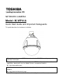
Model: IK-WP41A
Quick Start Guide and Important Safeguards
This guide describes the hardware installation.
Refer to the user's manual (PDF file) contained in the CD-ROM for settings, operations
and other information.
The application Adobe Reader is needed to view PDF files. If you do not have this
application, download it from the Adobe Systems Incorporated website.
http://www.adobe.com/
For information on our latest products and peripheral devices, refer to the following
Website:
http://www.toshibasecurity.com
If the URL changes, refer to the Toshiba website (http://www.toshiba.com).
Introduction
FCC (USA)-INFORMATION
NOTE: This equipment has been tested and found to comply with the limits for a
Class A digital device, pursuant to Part 15 of the FCC Rules.
These limits are designed to provide reasonable protection against harmful
interference when the equipment is operated in a commercial environment. This
equipment generates, uses, and can radiate radio frequency energy and, if not
installed and used in accordance with the instruction manual, may cause harmful
interference to radio communications. Operation of this equipment in a residential
area is likely to cause harmful interference in which case the user will be required
to correct the interference at his own expense.
USER-INSTALLER CAUTION: Your authority to operate this FCC verified
equipment could be voided if you make changes or modifications not expressly
approved by the party.
This device complies with Part 15 of the FCC Rules. Operation is subject to the
following two conditions:
(1) This device may not cause harmful interference, and
(2) this device must accept any interference received, including interference that
may cause undesired operation.
This Class A digital apparatus complies with Canadian ICES-003.
Cet appareil numé rique de la classe A est conforme à la norme
NMB-003 du Canada
1
Thank you for purchasing the IK-WP41A Network Camera. Before using the
camera, read this quick start guide carefully to ensure correct usage. After reading
this quick start guide, save it for future reference.
The design, specifications, software, and quick start guide contents are subject to
change without prior notice.
Terms and Trademarks
The term "OS" is used in this manual to indicate operating systems compatible
with this product.
-- Windows XP: Microsoft Windows XP operating system
-- Windows Vista: Microsoft Windows Vista Business operating system
-- Windows 7: Microsoft Windows 7 Professional operating system
The formal name of Windows is Microsoft Windows Operating System.
Microsoft, Windows and Windows Vista are trademarks or registered trademarks
of Microsoft Corporation in the United States and other countries.
Intel and Intel Core are trademarks or registered trademarks of
Intel Corporation or its subsidiaries in the United States and other
countries.
Adobe is a registered trademark and Adobe Reader is a trademark of Adobe
Systems Incorporated.
Other product names appearing in this quick start guide may be trademarks or
registered trademarks of their respective holders.
NOTE
The performance of the network camera may vary depending on the network
environment.
2
Table of Contents
Introduction ........................................................................................................................................................ 1
FCC (USA)-INFORMATION........................................................................................................................ 1
Important Safeguards....................................................................................................................................... 4
Important Safeguards (Cont.) ......................................................................................................................... 6
Notes on Use and Installation ......................................................................................................................... 7
Setting the Network Camera Environment ................................................................................................... 8
Package Contents ............................................................................................................................................ 9
Physical Description ......................................................................................................................................... 9
Hardware Installation...................................................................................................................................... 10
1.
Packing material, Silica-gel and micro SD/SDHC Card ................................................................ 10
2.
Install to the mounting bracket .......................................................................................................... 12
2.1
Wall Mount (JK-WM41A)................................................................................................................ 12
2.2 Wall Mount With Electrical Box (JK-WMB41A) ................................................................................ 14
3.
Cable connection ................................................................................................................................. 17
Network Deployment ...................................................................................................................................... 19
Log-in Screen .................................................................................................................................................. 21
Retrieving Images ........................................................................................................................................... 22
3
Important Safeguards
1. Read Instructions
Read all the safety and operating instructions before operating the product.
2. Retain Instructions
Retain the safety instructions and user's manual for future reference.
3. Warnings
Comply with all warnings on the product and in the user's manual.
4. Follow Instructions
Follow all operating and use instructions.
5. Cleaning
Disconnect this camera from the power supply before cleaning.
6. Attachments
Do not use attachments not recommended by the camera manufacturer as they may pose
safety risks.
7. Accessories
Do not place this camera on an unstable cart, stand, tripod, bracket or table. The camera
may fall, causing serious injury to a person, or serious damage to the product. Use only
with stand, tripod, bracket, or table recommended by the manufacturer, or sold with the
camera. Any mounting of the product should follow the manufacturer's instructions, and
should use a mounting accessory recommended by the manufacturer.
8. Ventilation
This camera should never be placed near or over a radiator or heat register. If this product
is placed in a built-in installation, verify that there is proper ventilation so that the camera
temperature operates within the recommended temperature range.
9. Power Sources
This camera should be operated only from the type of power source indicated on the
information label. If you are not sure of the type of power supply at your location, consult
your product dealer.
10. Power-Cord Protection
Power cords should be routed so that they are not likely to be walked on or pinched by
items placed upon or against them. Pay particular attention to cords at plugs, screws and
the point where they exit the product.
11. Installation
Install this camera on a secure part of the ceiling or wall. If installed on an unsecured
location, the camera could fall causing injury and damage.
6
4
12. Lightning
For additional protection on this camera during a lightning storm, or when it is left
unattended and unused for long periods of time, unplug it from the wall outlet and
disconnect the power supply and cable system. This will prevent damage to the camera
due to lightning and power-line surges. If lightning occurs, do not touch the unit or any
connected cables in order to avoid electric shock.
13. Overloading
Do not overload the power supply or extension cords as this can result in a risk of fire or
electric shock.
14. Object and Liquid Entry
Never push objects of any kind into this camera through openings as they may touch
dangerous electrical points or short-out parts that could result in a fire or electrical shock.
Never intentionally spill liquid of any kind on the camera.
15. Servicing
Do not attempt to service this camera yourself as opening or removing covers may expose
you to dangerous electrical or other hazards. Refer all servicing to qualified service
personnel.
16. Damage Requiring Service
Disconnect this camera from the power supply and refer servicing to qualified service
personnel under the following conditions.
a. When the power-supply cord or plug is damaged.
b. If liquid has been spilled, or objects have fallen into the camera.
c. If the camera has been submerged in water.
d. If the camera does not operate normally by following the operating instructions in the
user's manual. Adjust only those controls that are covered by the user's manual as
an improper adjustment of other controls may result in damage and will often require
extensive work by a qualified technician to restore the camera to its normal operation.
e. If the camera has been dropped or the cabinet has been damaged.
f. When the camera exhibiting a distinct change in performance which indicates a need for
service.
g. Other trouble.
17. Replacement Parts
When replacing parts, be sure the service technician uses parts specified by the
manufacturer or have the same characteristics as the original part. Unauthorized
substitutions may result in fire, electric shock or other hazards.
18. Safety Check
Upon completion of any service or repairs to this camera, ask the service technician to
perform safety checks to determine that the camera is in proper operating condition.
5
Important Safeguards (Cont.)
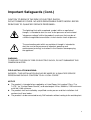
CAUTION TO REDUCE THE RISK OF ELECTRIC SHOCK.
DO NOT REMOVE COVER. NO USER SERVICEABLE PARTS INSIDE. REFER
SERVICING TO QUALIFIED SERVICE PERSONNEL.
The lightning flash with arrowhead symbol, within an equilateral
triangle, is intended to alert the user to the presence of uninsulated
"dangerous voltage" within the product's enclosure that may be of
sufficient magnitude to constitute a risk of electric shock to persons.
The exclamation point within an equilateral triangle is intended to
alert the user to the presence of important operating and
maintenance(servicing) instructions in the literature accompanying
the appliance.
WARNING:
TO REDUCE THE RISK OF FIRE OR ELECTRIC SHOCK, DO NOT SUBMARGE THIS
CAMERA IN WATER.
FIELD INSTALLATION MARKING:
WORDED: “THIS INSTALLATION SHOULD BE MADE BY A QUALIFIED SERVICE
PERSON AND SHOULD CONFORM TO ALL LOCAL CODES.”
NOTICE
The product is intended to be supplied by a Listed Power Unit marked "Class 2" or
"L.P.S." (or "Limited Power Source") and rated output 24Vac, 50-60Hz, 2.25A minimum
or 48Vdc, 0.6A minimum.
The product shall be installed by a qualified service person and the installation shall
conform to all local codes.
The product is to be connected to only PoE networks without routing to the outside plant.
6
Notes on Use and Installation
Do not aim the camera at the sun
Never aim the camera at the sun even with the camera power off.
Do not shoot intense light
Intense light such as a spotlight may cause a bloom or smear. A vertical stripe
may appear on the screen. However, this is not a malfunction.
Treat the camera with care
Dropping or subjecting the camera to intense vibration may cause it to
malfunction.
Never touch internal parts
Do not touch the internal parts of the camera other than the parts specified.
Do not submerge in water
The camera has some protection to water (see IP rating), and can be used
indoors or outdoors. If the camera was submerged in water, turn off the power
and contact your dealer.
Keep the camera installation away from video noise
If cables are wired near electric lighting wires or a TV set, noise may appear in
images. In this event relocate cables or reinstall equipment.
Check the ambient temperature and humidity
Avoid using the camera where the temperature is hotter or colder than the
specified operating range. Doing so could affect the internal parts or cause the
image quality to deteriorate. Special care is required to use the camera at high
temperature and humidity.
Should you notice any trouble
If any trouble occurs while you are using the camera, turn off the power and
contact your dealer. If you continue to use the camera when there is something
wrong with it, the trouble may get worse and an unpredictable problem may
occur.
7
Setting the Network Camera Environment
Items needed for network camera monitoring
Administrator's personal computer
The personal computer that allows setting, operating, monitoring and other
functions with the network camera is called the "administrator's personal
computer" in this guide.
The personal computer for viewing monitored images is called the "user's
personal computer" in this guide. The network camera can be viewed by more
than one personal computer at the same time.
Recommended personal computer system requirements:
-- Windows® XP, Windows Vista® Business, or Windows® 7 professional.
-- Internet Explorer® Ver 8.0 and 9.0
-- CPU: Intel® Core2 Duo 2.5GHz or greater
-- Memory: DDR2 2GB RAM or greater
Connection equipment such as CAT5e LAN cables, and switch or router.
-- The LAN cable type differs depending on the connection method.
Camera search application "IP Camera Finder"
-- Install this application from the CD-ROM supplied as an accessory
(Double-click "Setup.exe" in the CD-ROM and install the application by following
the onscreen instructions.)
-- This application is the tool to discover the IP address of a camera. Using this
application, the IP address of a camera can be easily determined.
8
Package Contents
IK-WP41A ---- 1
Allen wrench ---- 1
Torx wrench ---- 1
Screw (1/4-20UNC, 12mm) ---- 1
RJ45 Coupler ---- 1
Silica-gel ---- 1
CD-ROM ---- 1
Quick Start guide and Important Safeguards
Warranty ---- 1
---- 1
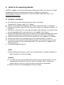
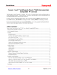
Physical Description
Unit: mm
9
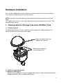
Hardware Installation
First, use the supplied torx wrench to detach the dome cover from the camera housing.
Then, follow the steps below to install the camera.
NOTE: Installation should be done only by qualified personnel and conform to all local
codes.
The supplied torx wrench is exclusively designed to match the dome cover screws. Don’t
discard the torx wrench
1. Packing material, Silica-gel and micro SD/SDHC Card
1.1 Packing material
Two packing materials on the lens module are for shipping only. Remove before use.
After that, attach this dome cover once again.
Detach the dome cover with
supplied Torx wrench.
Remove these packing
materials before use.
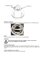
1.2 Attach a supplied silica-gel
(1) Remove a housing lid
Remove three hexagonal screws by supplied Allen wrench. And rotate housing head in
clockwise direction. You can detach housing lid.
10
Hexagonal screws
Housing Lid
(2) Attach a silica-gel
Get out the supplied silica-gel from the aluminum foil bag, and set it as attached image.
NOTE:
Treat silica-gel bag with care, Don’t tear the silica-gel package.
WARNING:
Keep the silica-gel out of the reach of babies, infants, and children.
DO NOT EAT, HARMFUL IF SWALLOWED
(3) Attach a housing Lid
Taking note of the arrowhead, attach a housing lid. Rotate counterclockwise, arrows are
united. Both arrowheads are faced, secure the three hexagonal screws with supplied Allen
wrench.
1.3 Micro SD/SDHC card installation
Refer to 11 pages of a user’s manual in the CD-ROM.
11
2. Install to the mounting bracket
IK-WP41A supports several mounting brackets like pendant mount, wall mount, etc. Select
an appropriate bracket according to your location, and purchase separately.
Here are major instance of installation. For more information about accessories, visit
www.toshibasecurity.com.
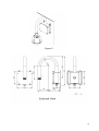
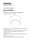
2.1 Wall Mount (JK-WM41A)
A) Drill 4 holes on the wall matching the mount holes on the plate.
Diameter φ3/8” (9.5mm), depth 1/1/2” (39mm).
B) Hammer 4 anchor bolts(not supplied) into the holes and secure them. (1) of Figure 1
C) Secure the connector ring of the accessory to this bracket in the clockwise direction. (2)
of Figure 1
D) Secure the safety wire to the screw hole on the back side of bracket. You need to fix the
wire with appropriate M4 screw and washer (not supplied). (3) of Figure 1
E) Remove the original connector ring of the camera, and thread the cabling of the camera
through the short aluminum tube and push the cables out to the wall. (4) of Figure 1
F) Secure this bracket to the wall with hex nuts and wrench (not supplied). (5) of Figure 1
G) Connect the camera to the connector ring in the clockwise direction. (Figure 2)
H) Use torx wrench to secure the attached fixing screw 1 to the connector ring. Use allen
wrench to secure the fixing screw to the bracket. This allen wrench is supplied in the
bracket (Figure 3)
I) Installation completed.(Figure 4)
NOTE:
When drilling the hole, please make sure the wall thickness is greater than 50mm in
order to maintain its structural integrity.
Warning:
The safety wire must be connected to the camera and wall mount bracket. This will
avoid personal hazards if the unit falls from its installation. When installing the
camera, please secure the safety wire to the screw holes on the bracket.
Make sure there are no damaged parts during assembly.
12
13
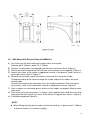
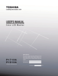
2.2
Wall Mount With Electrical Box (JK-WMB41A)
A) Drill 4 holes on the wall matching the mount holes on the plate.
Diameter φ3/8” (9.5mm), depth 1/1/2” (39mm)
B) Hammer 4 anchor bolts (not supplied) into the holes and secure them. (Figure 1)
C) Secure the electrical box to the wall with hex nuts and wrench (not supplied). (Figure 2)
D) Loosen the screws of the lid with a supplied torx wrench in the bracket. (Note: Leave in a
lower right screw shown in Figure 2.)
E) Remove the connector ring of the camera, and secure this ring to the U tube.
Thread the cabling of the camera through the U tube and push the cables out to the
electrical box.
Connect the camera to the connector ring in the clockwise direction.Then secure the
fixing screws 1and 2 to the connector ring with a supplied torx wrench. (Figure 3)
F) After all cables are connected; please make sure the cables are properly fitted to avoid
water leaks.
G) Secure the safety wire to position C in Figure 1 with supplied screw. And return the lid to
original position and secure the screws of the lid with a supplied torx wrench. (Figure 4)
H) Installation completed (Figure 5).
NOTE:
When drilling the hole, please make sure the wall thickness is greater than 2” (50mm)
in order to maintain its structural integrity.
14
Warning:
The safety wire must be connected to the camera and wall mount bracket. This will
avoid personal hazards if the unit falls from its installation. When installing the
camera, secure the safety wire to the screw holes on the bracket.
Make sure there are no damaged parts during assembly.
A
U tube
B
Hexagon head nuts
C
Screw for Safety Wire
15
16
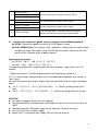
3.
Cable connection
No.
Connector
Descriptions
For Ethernet connection. Connects this port to the LAN port
of Ethernet switch via supplied coupler.
1
RJ-45 Connector
2
24V AC Power
Input(Black/White) and
Ground(Green)
Connect the power terminals to a 24V AC power supply and
ground the green wire.
3
Reset (Orange/White)
Using a pointed object, short both terminals to restart the
camera.
4
Audio In (Black/White)
Connect to an external microphone to this terminal.
(White: signal, Black:GND)
5
Alarm Out Open (Light Green) Connect to device that responds to alarm signals. “Com” and
Alarm Out Com (Black)
“Close” terminals are switched ON normally, and “Com” and
“Open” terminals are switched ON when Alarm is triggered.
Alarm Out Close (Purple)
Supporting PoE+, this port can connect to the PoE+ switch
or PoE+ injector.
17
Alarm In 5 (Blue)
6
Alarm In 6 (Green)
Connect to device that responds to alarm signals.
Alarm In GND (White)
7
8
9
3.1
Alarm In 1 (Red)
Alarm in 2 (Brown)
Alarm In 3 (Yellow)
Alarm in 4 (Orange)
Default (Pink/Gray)
Connect to device that triggers alarm signals.
Connect to device that triggers alarm signals.
Using a pointed object, short both terminals for about 5
seconds to restart the camera to the factory default.
Connect the camera to a power source, using one of the following options:
24V AC: Connect the power terminals to 24V AC power source.
PoE+ (IEEE802.3at): The camera is PoE+ compliant, allowing transmission of power
and data via single LAN cable. Using a CAT5e Ethernet cable, connect to the LAN
port of a PoE+ network switch or power injector.
Operating environment:
24V AC : –30 °C ~ +50 °C {–22 °F ~ 122 °F}*1
PoE+ : -10°C ~ +50 °C {14 °F ~122 °F} *1
The operating temperature range changes with kinds of power supply which uses this
camera.
*1 When the camera is installed and operated in low temperatures below 0 °C
{32 °F}, normal images and operations may not be obtained immediately after startup. In
such a case,
wait until the camera warms up as follows and start adjustment after turning on the power
again.
-10 °C ~ 0 °C {14 °F ~ 32 °F}, 24V AC or PoE+ Warms up taking more than 1
hour.
-30 °C ~ -10 °C {-22 °F ~ 14 °F}, 24V AC Warms up taking more than 3 hours.
CAUTION
All cables and power source are user-supplied.
Recommended 24V AC power cord is twisted pair line with a minimum wire size of 18
AWG.
Recommended 24V AC power supply for this camera is 75 watts minimum.
Use UL Listed Class 2 power supply.
When PoE+ is connected, don't supply 24V AC from the terminal.
18
3.2
Optional connection such as alarm in/out devices to the camera.
Network Deployment
1. Connect the Camera to the Network
Using an Ethernet cable (not supplied), connect one end to the RJ45 connector of the
camera and the other end to the LAN port of the network switch via supplied RJ45 coupler.
And connect your client PC to this network switch.
2. Install “IP Camera Finder” on your client PC
To make the camera accessible to your network, you must configure appropriate network
settings for the camera. To do so, you may install the provided IP Camera Finder on your
computer for initial setup purpose.
1. Insert the provided CD-ROM into your CD ROM drive.
2. Double-click Setup.exe of the folder of “IP Camera Finder”
3. Follow the prompts to finish installing.
4. The program automatically creates a shortcut icon on your desktop after it’s
successfully installed.
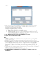
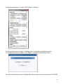
5. Start “IP Camera Finder” to Configure the Camera
Double-click the shortcut icon to launch the IP Camera Finder and click Search to start
searching the camera. All the cameras currently connected to the same network will
19
appear.
Click the camera you want to configure the network settings. If you have multiple
cameras connected to your local network, the MAC address on the camera to
distinguish the target camera from others.
Configure the following settings as needed.
Name: Enter a descriptive name for the camera.
Network Setting: If you have a DHCP server on your network to assign IP
addresses to network devices, enable the DHCP option. Otherwise, manually
enter the IP, Subnet Mask and Gateway settings.
Click Save to enable the settings and click Exit to exit the utility.
Double-Click the listed camera to login.
NOTE
If IP Camera Finder does not find the camera during the search, try turning off the
wireless LAN of a PC.
DHCP server needs to be doing normal performance, before turning on a camera.
IP Camera Finder can search the location of the Network Camera even though DHCP
is not used on the network. In this scenario, assign the camera a static IP address
because the IP address of the Network Camera has been assigned 169.254.*.* by
default.
Immediately after turning on a power of camera, even if IP camera finder displays an IP
address, it may sometimes be connectable.
In this case, please wait for 30 seconds and double-click.
IP Camera Finder is compatible only with Windows® XP, Windows Vista®, and
Windows® 7.
20
Log-in Screen
Double-Click the listed camera to login on the IP Camera Finder.
Input the administrator log-in ID and password in the user name and password fields and
click the OK button.
The administrator log-in ID and password are set to "admin" and to "1234" respectively
by default.
Important
Administrator Log-in allows rewriting of all settings. Be certain to change the administrator
log-in ID and password already set in the camera by default, to ensure camera security.
Keep the new administrator log-in ID and password handy for future use. To change the
administrator log-in ID and password, see "Administrator Password” of Configuration
Menu.
21
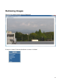
Retrieving Images
Retrieve live video through Internet Explorer®.
A menu is shown if the menu button on a screen is clicked.
22
A camera control panel is shown if PTZ Control is clicked.
A camera setup menu is shown if “Configuration” is clicked on the following screen.
A live video of camera is shown if “Live Video” is clicked on the following screen.
For more information on camera configuration, please refer to user’s manual on the CD-ROM
23
TOSHIBA AMERICA INFORMATION SYSTEMS, INC.
Surveillance & IP Video Products
9740 Irvine Boulevard,
Irvine, CA 92618-1697
Phone Number: (877) 855-1349
24