1
Model 12.5X
➤Owner’s Guide
limited lifetime consumer warranty
Directed Electronics ("Directed") promises to the original purchaser to repair or replace
with a comparable reconditioned model any Directed unit (hereafter the "unit"), excluding without limitation the siren, the remote transmitters, the associated sensors and accessories, which proves to be defective in workmanship or material under reasonable use during the lifetime of the vehicle provided the following conditions are met: the unit was professionally installed and serviced by an authorized Directed dealer; the unit will be professionally reinstalled in the vehicle in which it was originally installed by an authorized
Directed dealer; and the unit is returned to Directed, shipping prepaid with a legible copy
of the bill of sale or other dated proof of purchase bearing the following information: consumer's name, telephone number and address; the authorized dealers name, telephone
number and address; complete product description, including accessories; the year, make
and model of the vehicle; vehicle license number and vehicle identification number. All
components other than the unit, including without limitation the siren, the remote transmitters and the associated sensors and accessories, carry a one-year warranty from the date
of purchase of the same. This warranty is non-transferable and is automatically void if: the
original purchaser has not completed the warranty card and mailed it within ten (10) days
of the date of purchase to the address listed on the card; the unit's date code or serial number is defaced, missing or altered; the unit has been modified or used in a manner contrary to its intended purpose; the unit has been damaged by accident, unreasonable use,
neglect, improper service, installation or other causes not arising out of defects in materials or construction. The warranty does not cover damage to the unit caused by installation or removal of the unit. Directed, in its sole discretion, will determine what constitutes excessive damage and may refuse the return of any unit with excessive damage. TO
THE MAXIMUM EXTENT ALLOWED BY LAW, ALL WARRANTIES, INCLUDING BUT NOT LIMITED TO EXPRESS WARRANTY, IMPLIED WARRANTY,
WARRANTY OF MERCHANTABILITY, FITNESS FOR PARTICULAR PURPOSE
AND WARRANTY OF NON-INFRINGEMENT OF INTELLECTUAL PROPERTY,
ARE EXPRESSLY EXCLUDED; AND DIRECTED NEITHER ASSUMES NOR
AUTHORIZES ANY PERSON OR ENTITY TO ASSUME FOR IT ANY DUTY,
OBLIGATION OR LIABILITY IN CONNECTION WITH ITS PRODUCTS.
DIRECTED DISCLAIMS AND HAS ABSOLUTELY NO LIABILITY FOR ANY
AND ALL ACTS OF THIRD PARTIES INCLUDING ITS AUTHORIZED DEALERS OR INSTALLERS. DIRECTED SECURITY SYSTEMS, INCLUDING THIS
UNIT, ARE DETERRENTS AGAINST POSSIBLE THEFT. DIRECTED IS NOT
OFFERING A GUARANTEE OR INSURANCE AGAINST VANDALISM, DAMAGE OR THEFT OF THE AUTOMOBILE, ITS PARTS OR CONTENTS; AND
HEREBY EXPRESSLY DISCLAIMS ANY LIABILITY WHATSOEVER, INCLUDING WITHOUT LIMITATION, LIABILITY FOR THEFT, DAMAGE AND/OR
VANDALISM. THIS WARRANTY DOES NOT COVER LABOR COSTS FOR
MAINTENANCE, REMOVAL OR REINSTALLATION OF THE UNIT OR ANY
© 2006 directed electronics
i
CONSEQUENTIAL DAMAGES OF ANY KIND. IN THE EVENT OF A CLAIM
OR A DISPUTE INVOLVING DIRECTED OR ITS SUBSIDIARY, THE PROPER
VENUE SHALL BE SAN DIEGO COUNTY IN THE STATE OF CALIFORNIA.
CALIFORNIA STATE LAWS AND APPLICABLE FEDERAL LAWS SHALL APPLY
AND GOVERN THE DISPUTE. THE MAXIMUM RECOVERY UNDER ANY
CLAIM AGAINST DIRECTED SHALL BE STRICTLY LIMITED TO THE
AUTHORIZED DIRECTED DEALER'S PURCHASE PRICE OF THE UNIT.
DIRECTED SHALL NOT BE RESPONSIBLE FOR ANY DAMAGES WHATSOEVER, INCLUDING BUT NOT LIMITED TO, ANY CONSEQUENTIAL DAMAGES,
INCIDENTAL DAMAGES, DAMAGES FOR THE LOSS OF TIME, LOSS OF
EARNINGS, COMMERCIAL LOSS, LOSS OF ECONOMIC OPPORTUNITY
AND THE LIKE. NOTWITHSTANDING THE ABOVE, THE MANUFACTURER
DOES OFFER A LIMITED WARRANTY TO REPLACE OR REPAIR THE CONTROL MODULE AS DESCRIBED ABOVE. Some states do not allow limitations on
how long an implied warranty will last or the exclusion or limitation of incidental or consequential damages. This warranty gives you specific legal rights and you may also have
other rights that vary from State to State.
This product may be covered by a Guaranteed Protection Plan ("GPP"). See your authorized Directed dealer for details of the plan or call Directed Customer Service at 1-800876-0800. Directed security systems, including this unit, are deterrents against possible
theft. Directed is not offering a guarantee or insurance against vandalism, damage or theft
of the automobile, its parts or contents; and hereby expressly disclaims any liability whatsoever, including without limitation, liability for theft, damage and/or vandalism.
Directed does not and has not authorized any person or entity to create for it any other
obligation, promise, duty or obligation in connection with this security system.
Make sure you have all of the following information from your dealer:
A clear copy of the sales receipt, showing the following:
➤
➤
➤
➤
➤
➤
➤
➤
➤
ii
Date of purchase
Your full name and address
Authorized dealer's company name and address
Type of alarm installed
Year, make, model and color of the automobile
Automobile license number
Vehicle identification number
All security options installed on automobile
Installation receipts
© 2006 directed electronics
table of contents
limited lifetime consumer warranty . . . . . . . . . . . . . . . . . . . . . . . . . . . . . . . . . . . . . . . . i
2-way LCD remote control . . . . . . . . . . . . . . . . . . . . . . . . . . . . . . . . . . . . . . . . . . . . . 1
LCD screen . . . . . . . . . . . . . . . . . . . . . . . . . . . . . . . . . . . . . . . . . . . . . . . . . . . . . . . . . 2
standard remote configuration . . . . . . . . . . . . . . . . . . . . . . . . . . . . . . . . . . . . . . . . . . . 3
what is included . . . . . . . . . . . . . . . . . . . . . . . . . . . . . . . . . . . . . . . . . . . . . . . . . . . . . . 4
important information . . . . . . . . . . . . . . . . . . . . . . . . . . . . . . . . . . . . . . . . . . . . . . . . . 4
system maintenance . . . . . . . . . . . . . . . . . . . . . . . . . . . . . . . . . . . . . . . . . . . . . . 5
fcc/id notice . . . . . . . . . . . . . . . . . . . . . . . . . . . . . . . . . . . . . . . . . . . . . . . . . . . . 6
replacement remote controls . . . . . . . . . . . . . . . . . . . . . . . . . . . . . . . . . . . . . . . . . . . . 7
2-way LCD remote control functions . . . . . . . . . . . . . . . . . . . . . . . . . . . . . . . . . . . . . 7
standard configurations (1-way and 2-way remote controls) . . . . . . . . . . . . . . . . 7
standard LCD icon configurations (2-way only) . . . . . . . . . . . . . . . . . . . . . . . . . 9
remote operation . . . . . . . . . . . . . . . . . . . . . . . . . . . . . . . . . . . . . . . . . . . . . . . . . . . . 14
system signal paging features . . . . . . . . . . . . . . . . . . . . . . . . . . . . . . . . . . . . . . . 14
out of range notification . . . . . . . . . . . . . . . . . . . . . . . . . . . . . . . . . . . . . . . . . . 15
programming LCD remote . . . . . . . . . . . . . . . . . . . . . . . . . . . . . . . . . . . . . . . . . . . . 16
To enter programming mode . . . . . . . . . . . . . . . . . . . . . . . . . . . . . . . . . . . . . . 16
Beeps/Vibration On/Off . . . . . . . . . . . . . . . . . . . . . . . . . . . . . . . . . . . . . . . . . . 16
Illumination On/Off. . . . . . . . . . . . . . . . . . . . . . . . . . . . . . . . . . . . . . . . . . . . . 17
Page notification . . . . . . . . . . . . . . . . . . . . . . . . . . . . . . . . . . . . . . . . . . . . . . . . 17
To exit programming mode. . . . . . . . . . . . . . . . . . . . . . . . . . . . . . . . . . . . . . . . 17
using your system . . . . . . . . . . . . . . . . . . . . . . . . . . . . . . . . . . . . . . . . . . . . . . . . . . . 18
active arming. . . . . . . . . . . . . . . . . . . . . . . . . . . . . . . . . . . . . . . . . . . . . . . . . . . 18
passive arming . . . . . . . . . . . . . . . . . . . . . . . . . . . . . . . . . . . . . . . . . . . . . . . . . . 19
multi-level security arming . . . . . . . . . . . . . . . . . . . . . . . . . . . . . . . . . . . . . . . . 20
disarming . . . . . . . . . . . . . . . . . . . . . . . . . . . . . . . . . . . . . . . . . . . . . . . . . . . . . 21
disarming without a transmitter . . . . . . . . . . . . . . . . . . . . . . . . . . . . . . . . . . . . 23
dome light control . . . . . . . . . . . . . . . . . . . . . . . . . . . . . . . . . . . . . . . . . . . . . . 24
silent mode . . . . . . . . . . . . . . . . . . . . . . . . . . . . . . . . . . . . . . . . . . . . . . . . . . . . 24
panic mode . . . . . . . . . . . . . . . . . . . . . . . . . . . . . . . . . . . . . . . . . . . . . . . . . . . . 25
valet mode. . . . . . . . . . . . . . . . . . . . . . . . . . . . . . . . . . . . . . . . . . . . . . . . . . . . . 26
nuisance prevention® circuitry . . . . . . . . . . . . . . . . . . . . . . . . . . . . . . . . . . . . . 27
auxiliary outputs (options) . . . . . . . . . . . . . . . . . . . . . . . . . . . . . . . . . . . . . . . . . . . . . 29
shock sensor adjustment . . . . . . . . . . . . . . . . . . . . . . . . . . . . . . . . . . . . . . . . . . . . . . 30
To enter shock sensor adjustment mode:. . . . . . . . . . . . . . . . . . . . . . . . . . . . . . 30
Adjusting the Shock Sensor Setting. . . . . . . . . . . . . . . . . . . . . . . . . . . . . . . . . . 31
Exit Shock Sensor Adjustment Mode: . . . . . . . . . . . . . . . . . . . . . . . . . . . . . . . . 34
Reset Shock Sensor to Default Setting: . . . . . . . . . . . . . . . . . . . . . . . . . . . . . . . 34
© 2006 directed electronics
iii
diagnostics . . . . . . . . . . . . . . . . . . . . . . . . . . . . . . . . . . . . . . . . . . . . . . . . . . . . . . . . . 35
arming diagnostics . . . . . . . . . . . . . . . . . . . . . . . . . . . . . . . . . . . . . . . . . . . . . . 35
disarming diagnostics . . . . . . . . . . . . . . . . . . . . . . . . . . . . . . . . . . . . . . . . . . . . 36
table of zones . . . . . . . . . . . . . . . . . . . . . . . . . . . . . . . . . . . . . . . . . . . . . . . . . . 37
interpreting zone diagnostics . . . . . . . . . . . . . . . . . . . . . . . . . . . . . . . . . . . . . . . 38
owner recognition . . . . . . . . . . . . . . . . . . . . . . . . . . . . . . . . . . . . . . . . . . . . . . . . . . . 39
rapid resume logic . . . . . . . . . . . . . . . . . . . . . . . . . . . . . . . . . . . . . . . . . . . . . . . . . . . 39
power saver mode . . . . . . . . . . . . . . . . . . . . . . . . . . . . . . . . . . . . . . . . . . . . . . . . . . . 40
programming . . . . . . . . . . . . . . . . . . . . . . . . . . . . . . . . . . . . . . . . . . . . . . . . . . . . . . . 41
installation options . . . . . . . . . . . . . . . . . . . . . . . . . . . . . . . . . . . . . . . . . . . . . . . . . . 45
vehicle recovery system (vrs®) . . . . . . . . . . . . . . . . . . . . . . . . . . . . . . . . . . . . . . . . . . 45
arming the vrs® . . . . . . . . . . . . . . . . . . . . . . . . . . . . . . . . . . . . . . . . . . . . . . . . 46
vrs® triggered sequence . . . . . . . . . . . . . . . . . . . . . . . . . . . . . . . . . . . . . . . . . . 47
disarming the vrs® . . . . . . . . . . . . . . . . . . . . . . . . . . . . . . . . . . . . . . . . . . . . . . 48
programming options . . . . . . . . . . . . . . . . . . . . . . . . . . . . . . . . . . . . . . . . . . . . . . . . 49
security & convenience expansions . . . . . . . . . . . . . . . . . . . . . . . . . . . . . . . . . . . . . . 50
glossary of terms . . . . . . . . . . . . . . . . . . . . . . . . . . . . . . . . . . . . . . . . . . . . . . . . . . . . 53
quick reference guide . . . . . . . . . . . . . . . . . . . . . . . . . . . . . . . . . . . . . . . . . . . . . . . . . 55
iv
© 2006 directed electronics
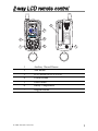
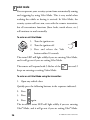
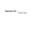
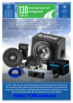
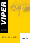
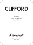
2-way LCD remote control
6
2
4
1
5
1.
Auxiliary Channel Button
2.
Arm Button
3.
LCD Screen (see LCD Screen)
4.
Disarm Button
5.
Panic Button
6.
Battery Compartment
7.
Program Button
© 2006 directed electronics
1-800-274-0200
RPN 489V/P/X
2(66) CODES
FCC ID:EZSDEI489
3
7
1
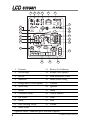
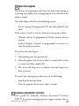
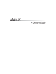
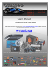
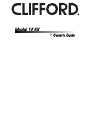
LCD screen
1
2
3
4
5
6
7
23
22
8
9
21
20
10
19
18
11
12
17
13
16
15
14
1. Transmit
13. Battery level indicator
2. Out of range
14. Remote start (option)
3. Receive
15. Field disturbance sensor *
4. Auxiliaries
16. Shock sensor setting
5. Garage door (519H2 option)
17. Vibrator
6. Warn Away®
18. Ignition
7. Alarm
19. Hood
8. Ultrasonic sensor *
20. Vehicle number
9. Tilt sensor *
21. Door
10. Trunk
22. Arm
11. Glass breakage sensor *
23. Disarm
12. Shock sensor
* Optional sensors. Additional parts and labor required
2
© 2006 directed electronics
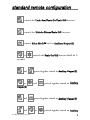
standard remote configuration
controls the Lock–Arm/Panic On/Panic Off function.
controls the Unlock–Disarm/Panic Off function.
controls Silent Mode™ and an Auxiliary Output (2).
or
controls the Panic On/Off function (hold for 2-
seconds).
and
pressed together control an Auxiliary Output (3).
or
and
pressed together control an Auxiliary
Output (4).
and
and
© 2006 directed electronics
pressed together control an Auxiliary Output (5).
or
pressed together control an Auxiliary
3
Output (6).
P
(located on back of the remote) selects the vehicle to control
and also provides user selection of LCD remote response .
what is included
➤
➤
Control module
1 four-button 2-way LCD transmitter
➤
1 four-button transmitter
note: On both remotes the panic button is the same color.
➤
➤
➤
➤
➤
➤
➤
➤
Wire harnesses
Dual diode harness
The 514N six-tone programmable siren
In-vehicle status LED indicator light
A push-button Valet switch
Your warranty registration
Failsafe® Starter Kill ready circuitry
(may require additional labor)
548T transceiver/antenna
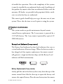
important information
Congratulations on the purchase of your state-of-the-art vehicle
security system. This system has been designed to provide years
4
© 2006 directed electronics
of trouble-free operation. Due to the complexity of this system,
it must be installed by an authorized dealer only. Installation of
this product by anyone other than an authorized dealer voids the
warranty. All dealers are provided with preprinted dealer certificates to verify that they are authorized.
This owner’s guide should help you to get the most out of your
system. Please take the time to read it prior to using the system.
➜ system maintenance
This system needs no specific maintenance beyond remote
control battery replacement. The 2-way remote is powered by a
1.5V AAA battery. The 1-way remote is powered by a pair of 3V,
CR2016 batteries.
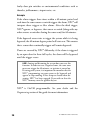
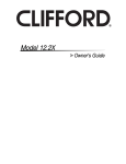
Battery Level Indicator (2-way remote)
The Battery Level indicator has four level indicators that serve as
a visual indication of battery charge. When the battery reaches a
low charge level that requires replacement, the remote control
will generate a single notification chirp, and the Battery Level
indicator will flash continuously.
FULL
REPLACE
EMPTY
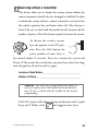
Battery Replacement (2-way remote)
Gently pull the end of the battery door away from the top of the
remote control then slide the door up to expose the battery and
remove the expired battery. Place the new battery into the remote
© 2006 directed electronics
5
control observing the correct polarity. When power is returned
the remote control will display all icons in the LCD and generate
all beeper tones once. Press any button on the remote to terminate the beeper tone review.
➜ your warranty
Your warranty registration must be returned and the bar code
serial number must not be removed. If the warranty registration
is not returned, you do not have a warranty. It is also necessary
to keep your proof of purchase, which reflects that the product
was installed by an authorized dealer. Make sure that you receive
the warranty registration from your dealer.
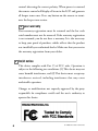
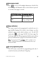
➜ fcc/id notice
This device complies with Part 15 of FCC rules. Operation is
subject to the following two conditions: (1) This device may not
cause harmful interference, and (2) This device must accept any
interference received, including interference that may cause
undesirable operation.
Changes or modifications not expressly approved by the party
responsible for compliance could void the user's authority to
operate this device.
6
© 2006 directed electronics
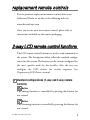
replacement remote controls
You can purchase replacement remote controls from your
Authorized Dealer or on-line at the following web site:
www.directedstore.com
Once you receive your new remote control, please refer to
instructions included on the remote packaging.
2-way LCD remote control functions
The LCD remote control buttons are used to send commands to
the system. The descriptions below reflect the standard configuration for this system. The buttons can be custom configured for
the user’s specific needs by the installer. Also, the user can
configure the LCD remote for certain responses (see
Programming LCD Remote section).
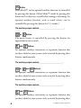
➜ standard configurations (1-way and 2-way remote
controls)
Button
The arming function is controlled by pressing this button for
one second.
Button
The disarming function is controlled by pressing this button for
one second.
© 2006 directed electronics
7
Button
Silent Mode™ and an optional auxiliary function are controlled
by pressing this button. (Silent Mode™ works by pressing this
button for less than one second before arming or disarming. An
optional auxiliary function, such as trunk release, can be
controlled by pressing this button for 1.5 seconds.)
The auxiliary output controls __________________________.
or
Button
The panic feature is controlled by pressing this button for
approximately two seconds.
and
Buttons
An optional auxiliary convenience or expansion function that
you have added to your system can be activated by pressing these
buttons simultaneously.
The auxiliary output controls_________________________.
or
and
Buttons
An optional auxiliary convenience or expansion function that
you have added to your system can be activated by pressing these
buttons simultaneously.
The auxiliary output controls_________________________.
and
Buttons
An optional auxiliary convenience or expansion function that
you have added to your system can be activated by pressing these
8
© 2006 directed electronics
buttons simultaneously.
The auxiliary output controls_________________________.
and
or
Buttons
An optional auxiliary convenience or expansion function that
you have added to your system can be activated by pressing these
buttons simultaneously.
The auxiliary output controls_________________________.
Program Button (on
rear of 2-way LCD remote only)
Use this button to select the vehicle to control from the remote.
Also use this button to configure response characteristics from
the LCD remote (see Programming 2-Way Remote).
➜ standard LCD icon configurations (2-way only)
Icon
The transmit icon will be displayed while the remote control is
transmitting a command to the vehicle.
Icon
The signal icon will be displayed if a command is transmitted to
the vehicle but the command page is not received.
Icon
The receive icon will be displayed while the remote control is
receiving a page from the vehicle.
Icon
The auxiliary and sensor icons will display which auxiliary is oper© 2006 directed electronics
9
ating, or which security sensor (zone 2,4 or 7) is in Warn Away®
or alarm state.
Icon
The garage door icon—for use with optional 519H2.
and
Icons
The above Warn Away® displays when a security feature has been
tripped, but not to full alarm.
and
Icons
The above icons will display when a security feature has been
tripped to a full alarm condition.
Icon
The ultrasonic sensor (detects motion within the vehicle) icon
will display for full alarm by flashing for a few seconds and then
display continuously until the page is cleared.
Icon
The tilt sensor icon will display for full alarm by flashing for a
few seconds and then display continuously until the page is
cleared.
Icon
The trunk icon will display for full alarm by flashing for a few
seconds and then display continuously until the page is cleared.
Icon
The glass breakage sensor icon will display for full alarm by
10
© 2006 directed electronics
flashing for a few seconds and then display continuously until
the page is cleared.
Icon
The shock sensor icon will display for both Warn Away® and full
alarm by flashing for a few seconds and then display continuously until the page is cleared.
Icon
The battery icon always displays the current charge capacity
remaining in the remote’s battery.
Icon
The remote start (option) icon displays when the vehicle is being
remote started.
Icon
The field disturbance sensor icon will display for both Warn
Away® and full alarm by flashing for a few seconds and then
display continuously until the page is cleared.
Icon
The shock sensor bar icon always displays the current sensitivity
setting of the shock sensor.
Icon
The shock sensor “sensor” icon will display for both Warn Away®
and full alarm by displaying continuously until the page is
cleared.
© 2006 directed electronics
11
Icon
The vibrator icon will always display if the remote is
programmed for vibrator notification (see programming LCD
remote section of the guide).
Icon
The ignition icon will display for full alarm by flashing for a few
seconds and then display continuously until page is cleared.
Icon
The hood icon will display for full alarm by flashing for a few
seconds and then display continuously until the page is cleared.
Icon
The vehicle icon always displays the current vehicle (maximum
of 4 vehicles) being controlled by the remote. If a Warn Away®
or alarm trigger should occur at one of the other vehicles, that
vehicle’s number will be displayed and the LCD will display that
vehicle’s status. To change back to the original vehicle selected,
press and release the program button until the vehicle number is
shown.
For example, If the remote was originally on vehicle number 1 and
a trigger page was received for vehicle number 2, the remote will
show the trigger alarm and show number 2 on the display. After
clearing the page, press and release the program button until number
1 is displayed. Now you can operate the alarm system on vehicle
number 1.
12
© 2006 directed electronics
Icon
The door icon will display for full alarm by flashing for a few
seconds and then display continuously until the page is cleared.
Icon
The arm icon will flash when the system is locking the doors and
display continuously until the system is armed.
Icon
The disarm icon will flash when the system is unlocking the
doors and display continuously until the system is disarmed.
© 2006 directed electronics
13
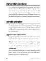
transmitter functions
This system uses a computer-based learn routine to learn the
transmitter buttons. This makes it possible to assign any transmitter button to any system function. The transmitter initially
comes programmed with Standard Configuration, but may also
be customized by an authorized dealer. The buttons described in
this manual correspond to a Standard Configuration transmitter.
remote operation
The system operates at 434 MHz and incorporates Directed’s proprietary out-board technology transceiver. The high frequency combined
with Binary Data communication achieves superior range with twoway communication.
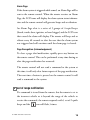
➜ system signal paging features
A page is the signal the control module sends to the remote control
as confirmation of receipt of a command or alarm system status.
When the remote control receives a page it will generate a page
notification to the user (notifications are audible beeps and-or
vibration) and the LCD Icons will display the current system status.
Command Page
When a command (arm/disarm, or auxiliary channel) from the
remote control is sent and received, the system will send a
command page back to confirm receipt.
14
© 2006 directed electronics
Alarm Page
If the alarm system is triggered while armed, an Alarm Page will be
sent to the remote control. When the remote receives an Alarm
Page, the LCD icons will display the alarm system status information and the remote control will generate beeps and-or vibration.
An Alarm Page alert is a series of 5 groups of 4 rapid beeps
(shock, trunk, door, ignition, or hood trigger) and the LCD icon
that caused the alarm will display. The remote will beep and or
vibrate every 60 seconds to alert the user that the alarm system
was triggered and will continue until the alarm page is cleared.
Page Recognition (Acknowledgement)
To clear a page alert/notification, quickly press any button on
the remote control. This can be performed at any time during or
after the page notification has occurred.
The remote control will not send a command to the system at
this time; it will only clear future repeats of the page notification.
The next time a button is pressed on the remote control it will
send a command to the system.
➜ out of range notification
If a command is issued from the remote, but the remote is set to
the incorrect vehicle or is beyond the range of the vehicle to
receive the command, the remote responds with 3 set of 2 quick
beeps and the
© 2006 directed electronics
icon will flash 3-times.
15
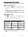
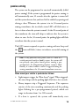
programming LCD remote
➜ To enter programming mode
Press and hold the
P
button until one long beep is heard.
Programming mode to customize the remote’s response is now
entered.
note: If no buttons are pressed within 5-seconds, programming mode will exit with 2-beeps.
➜ Beeps/Vibration On/Off
Press
to select beeps/vibration On/Off. Beeps alone, vibra-
tion alone, beeps and vibration, or no beeps and vibration can be
selected. Refer to the table below for these settings.
Beep/Vibrate settings
Programming response Icon display*
Beeps only (default)
1-beep
Siren icon On
Vibrate only
1-vibrate
Vibrate icon On
Beep & Vibrate
1-beep and 1-vibrate
No Beep and No Vibrate 1 long beep
Vibrate and siren icon
On
Vibrate and siren
icons Off
*Note: This is icon display during programming.
16
© 2006 directed electronics
➜ Illumination On/Off
Press
to select LCD backlight illumination On/Off. The
LCD backlight will illuminate when a remote button is pressed,
or an alarm status page is received.
LCD Backlight settings Programming response
ON
1-beep, backlight ON
OFF
2-beeps, backlight OFF
➜ Page notification
The remote control can be programmed to notify the user of a
page (audibly beeping if the vehicle’s status changes, e.g. door
unlocked, engine started, vehicle violation, etc.). On the LCD
remote press
to select page On/Off. One beep is page On,
Two beeps is page Off. When programmed off the remote will not
give any notification that a page was received from the vehicle.
Note: If programmed Off, no alarms will be notified to the
remote. Command information (armed/disarmed) will be notified to the remote.
➜ To exit programming mode
The LCD remote control will exit programming mode after 5seconds of inactivity and will emit 2 long beep.
© 2006 directed electronics
17
using your system
The buttons described in this manual correspond to the standard
configuration. Remember, this is not the only way your transmitter may be set up. It can be custom configured to meet your
needs. See your installer for additional details.
➜ active arming
You can arm the system by pressing
of your remote for one
second. When the system arms, from the vehicle you will hear a
short siren sound, or chirp, and see the parking lights flash once.
If the power door locks are controlled by the system, the doors
will also lock. While the system is armed, the in-vehicle’s status
LED will flash approximately once per second, indicating that
the system is actively protecting your vehicle. If you hear a
second chirp after arming and note that the in-vehicle’s status
LED is flashing in groups, see the Diagnostics Section of this
guide. This extra chirp is called Bypass Notification.
The LCD remote responds to active arming with one beep and
the
icon will flash 5-times to indicate successful arming of
the system.
If the LCD remote beeps twice after arming, the system has detected
an active sensor that should be checked. For example, a door open
icon will be displayed flashing 5-times on the LCD screen.
18
© 2006 directed electronics
passive arming
The system can be programmed to arm itself automatically (called
passive arming). If the system is programmed for passive arming, it
will automatically arm 30 seconds after the ignition is turned off
and the system detects that you have left the vehicle by opening and
closing a door. Whenever the system is in its 30-second passive
arming countdown, the in-vehicle status LED will flash twice as
fast as it does when the system is armed. At the 20-second point of
the countdown, the siren will chirp to indicate that the system is
about to arm. At the 30-second point, the parking lights will flash
to indicate that the system is armed.
The LCD remote responds to passive arming with one beep and
the
icon will flash 3-times to indicate successful arming of
the system.
note: If any protected entry point (such as a door or a
switch-protected trunk or hood) is open, the system will
not passively arm (unless forced passive arming is programmed on. See Programming Options section.) Additionally, if a door, hood or trunk is triggered during the
arming countdown, the 30-second countdown starts over.
When armed your vehicle is protected as follows:
➤
➤
➤
Light impacts trigger the Warn Away® signal. When triggered,
the siren chirps and the parking lights flash for a few seconds.
Heavy impacts trip a Triggered Sequence. The sequence
consists of the siren sounding continuously and the parking
lights flashing for a pre-programmed period, which can
range in duration from 1 to 180 seconds.
If a door is opened, the system will immediately start
© 2006 directed electronics
19
➤
➤
➤
chirping the siren and flashing the parking lights. Three
seconds later, the siren output changes to a continuous blast.
This progressive response gives you time to disarm the system with your LCD remote if you inadvertently open the
door while the system is armed, while still providing instant
response (even if the door is immediately closed).
Turning on the ignition key will trip the same progressive response as opening a door.
The optional starter kill prevents the vehicle’s starter from
cranking.
Any full trigger of the alarm system will immediately send an
alarm page to your remote informing you that your vehicle
should be checked.
➜ multi-level security arming
Multi-Level Security Arming allows you to select which of the
security system's inputs or sensors will be active and which will
be bypassed at the time that the system is armed. (See the Table
of Zones section of this guide.) Pressing
again within five
seconds of arming the security system will activate the MultiLevel Security Arming feature. Each time
is pressed again, a
different security level is selected. The different security levels
can be selected as follows:
➤
Press
once: The siren chirps once. The system is armed.
➤
Press
a second time within five seconds: The parking
lights flash twice. Zone 2 is now bypassed.
➤
Press
a third time within five seconds: The parking
lights flash three times. Zone 4 is now bypassed.
20
© 2006 directed electronics
➤
Press
a fourth time within five seconds: The parking lights
flash four times. Zone 7 is now bypassed.
➤
Press
a fifth time within five seconds: The parking
lights flash five times. Zones 2 and 4 are now bypassed.
➤
Press
a sixth time within five seconds: The parking
lights flash six times. Zones 2 and 7 are now bypassed.
➤
Press
a seventh time within five seconds: The parking
lights flash seven times. Zones 4 and 7 are now bypassed.
➤
Press
an eighth time within five seconds: The parking
lights flash eight times. All zones except zone 5 are now
bypassed.
note: Multi-Level Security Arming only applies to a single arming cycle. Once the system is disarmed and then
re-armed, all the zones will be active again.
After each press of the
to reach the next level of security, the
remote will emit normal arm notification (1 beep and 5 flashes
of the
icon). For easiest operation in reaching each level of
security, press
immediately after each notification.
➜ disarming
To disarm the system, press
. You will hear two chirps, and
the parking lights will flash twice. If the power locks are
connected to the system, the doors will unlock. If the siren chirps
either four or five times when disarming, refer to the Diagnostics
section of this guide. This is called Tamper Alert.
© 2006 directed electronics
21
The remote will indicate disarm notification with 2 beeps and 5
flashes of the
icon. If disarming after the system has been
triggered, the remote control will send a diagnostic notification
as a reminder. These diagnostic notifications are:
1. If a sensor triggered the system, the remote will emit 4 quick
beeps and the LCD screen will indicate which sensor (5flashes) tripped the alarm.
2. If a switch (Zone 1, 3, 5, or 6) triggered the system, the
remote will emit 4 quick beeps and the LCD screen will
indicate which switch (5-flashes) tripped the alarm.
3. If the system was triggered so many times that NPC is active
the remote will emit the above notifications with 5 beeps
instead of 4.
22
© 2006 directed electronics
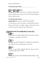
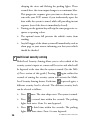
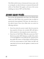
➜ disarming without a transmitter
This feature allows you to disarm the security system without the
remote transmitter should it be lost, damaged, or disabled. In order
to disarm the system without a remote transmitter, you must have
the vehicle’s ignition key and know where the Valet button is
located. Be sure to check with the installer for the location and the
number of presses of the Valet button required to disarm the system.
To disarm the security system,
turn the ignition to the ON position. Press the Valet button the
preset number of times (one to
DRW-35
five times) within 15 seconds. After five seconds the system will
disarm. If the system does not disarm, you may have waited too long;
turn the ignition off and on and try again.
Location of Valet Button_________________________________
Number of Pulses______________________________________
important! The unit can be programmed to respond to
one to five pulses of the Valet button for the disarm function. Be sure to check with the installer for the desired
programming.
The LCD remote will indicate disarm notification with 4 quick
beeps and 5 flashes of the
© 2006 directed electronics
and triggered zone icons.
23
➜ dome light control
security only
The dome light activates for 30-seconds after the system is
disarmed.
Ignition controlled
The dome light activates for 30-seconds after the ignition is
turned Off.
door controlled
The dome light activates for 30-seconds after the system sees a
door has closed. (If door was held open for longer than 3
minutes the dome light will not illuminate.)
full
The dome light activates for 30-seconds after seeing door
closure, ignition, or security disarm. (This is the factory setting.)
➜ silent mode
To temporarily turn off the arm or disarm chirps, use Silent
Mode™. Simply press
for less than one second before
arming or disarming, and the confirmation chirp(s) will be eliminated for that one operation only. If you want the arm/disarm
chirps turned off permanently, your dealer can do this for you.
note: The Warn Away® response to lighter impacts is
bypassed if the system is armed using Silent Mode. This
ensures that no chirps will be emitted by the siren in an
area you want chirp-free. The system is still fully capable
of triggering. Only the Warn Away® response is bypassed.
24
© 2006 directed electronics
The LCD remote responds with the normal arm/disarm notifications in silent mode. (If the remote has beeps programmed
On, the remote will beep.)
➜ panic mode
note: On both remotes the panic button is the same color.
LCD remote
If you are threatened in or near your vehicle, you can attract
attention by triggering the system with your LCD remote. Just
press
or
button for approximately two seconds, and
you will enter Panic Mode. The siren will sound and the parking
lights will flash for the programmed siren duration. To stop
Panic Mode at any time, press
or
button on the LCD
remote again.
The LCD remote responds with one beep and display of the
icon upon entering Panic Mode.
4-button remote
If you are threatened in or near your vehicle, you can attract
attention by triggering the system with your transmitter. Just
press
or
for approximately two seconds, and you will
enter Panic Mode. The siren will sound and the parking lights
will flash for the programmed siren duration. To stop Panic Mode
at any time, press
© 2006 directed electronics
, or
on the remote transmitter again.
25
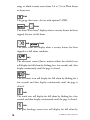
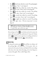
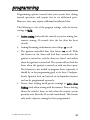
➜ valet mode
You can prevent your security system from automatically arming
and triggering by using Valet Mode. This is very useful when
washing the vehicle or having it serviced. In Valet Mode, the
security system will not arm, even with the remote transmitter,
but all convenience functions (door locks, trunk release, etc.)
will continue to work normally.
To enter or exit Valet Mode:
1. Turn the ignition on.
2. Turn the ignition off.
3. Press and release the Valet
DRW-35
button within 10 seconds.
The status LED will light solidly if you are entering Valet Mode,
and it will go out if you are exiting Valet Mode.
The remote will respond with 5-flashes of the
icon and 2
beeps on entering or exiting Valet® Mode.
To enter or exit Valet Mode using the transmitter:
1. Open any vehicle door.
Quickly press the following buttons in the sequence indicated.
2. Press
.
3. Press
.
4. Press
again.
The in-vehicle status LED will light solidly if you are entering
Valet® Mode, and it will go out if you are exiting Valet® Mode.
26
© 2006 directed electronics
➜ one-time bypass
This feature (if programmed on) stops the alarm from arming or
activating any outputs that are programmed to activate when the
alarm is armed.
One-time bypass will defeat the following actions:
Passive arming: If programmed ON the alarm will not arm
itself.
If the remote is used to arm the alarm after exiting the vehicle:
Window roll up: If programmed ON this output will not
activate.
Linked Auxiliary Outputs: If programmed to activate on
arm, they will not activate.
To activate one-time bypass:
1. After parking turn the ignition off.
2. Turn the ignition On for more than 1-second and less than
3-seconds and then turned Off.
3. The siren will chirp once to indicate one-time bypass has
been activated.
To cancel one-time bypass perform one of the following:
Arm then disarm the alarm.
Turn the ignition On for more than 3-seconds.
➜ nuisance prevention® circuitry
Your system has Directed’s Nuisance Prevention® Circuitry
(NPC®). It prevents annoying repetitive trigger sequences due to
© 2006 directed electronics
27
faulty door pin switches or environmental conditions such as
thunder, jackhammers, airport noise, etc.
Example
If the alarm triggers three times within a 60-minute period and
each time the same sensor or switch triggers the alarm, NPC® will
interpret those triggers as false alarms. After the third trigger,
NPC® ignores, or bypasses, that sensor or switch (along with any
other sensors or switches sharing the same zone) for 60 minutes.
If the bypassed sensor tries to trigger the system while it is being
bypassed, the 60-minute bypass period will start over. This ensures
that a sensor that continually triggers will remain bypassed.
Doors are covered by NPC® differently; if the alarm is triggered
by an open door for three full cycles, the doors will be bypassed
until the trigger ceases.
note: Arming and disarming the system does not reset this
function. In order to reset a bypassed zone, the same zone
must not trigger for 60 minutes, or ignition is turned on.
If testing your system, it is important to remember that the
NPC® programming can cause zones to be bypassed and
appear to stop working. If five chirps are heard when disarming, NPC® has been engaged. If you wish to clear the
NPC® memory, turn the ignition key on.
NPC® is On/Off programmable. See your dealer and the
Programming section of this guide for more information.
28
© 2006 directed electronics
auxiliary outputs (options)
This system also supplies outputs that can control convenience
options such as remote control trunk release and window automation. Consult your dealer for available options for your system.
Channel 2 Trunk release: When connected, pressing
for 1.5
seconds will remotely release the vehicle trunk lid.
Channel 3 auxiliary output: When connected, pressing
and
will immediately activate this output to control an
additional convenience option.
Channel 4 auxiliary output: When connected, pressing
and
will immediately activate this output to control an
additional convenience option.
Channel 5 auxiliary output: When connected, pressing
and
will immediately activate this output to control an
additional convenience option.
Channel 6 auxiliary output: When connected, pressing
or
and
will immediately activate this output to
control an additional convenience option.
The remote will respond with a page notification consisting of
one long beep and for 4-seconds displays the channel number on
the LCD screen. This occurs at the remote after the system has
received the command to activate any of the Auxiliary outputs.
© 2006 directed electronics
29
shock sensor adjustment
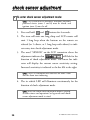
➜ To enter shock sensor adjustment mode:
note: The system must be disarmed, and doors and other
protected entries (zones 1 and 6) must be closed, and
ignition (zone 5) must be off.
1. Press and hold
and
buttons for 4-seconds.
2. The siren will emit one long chirp and LCD remote will
emit 1 long beep when the buttons on the remote are
released (or 1 vibrate, or 1 long beep with vibrate) to indicate entry into shock adjustment mode.
3. The word “SENSOR” on the LCD transmitter above the
adjustment indicator bar
will flash for the
duration of shock adjustment mode. The sensor bar indicator will display the current sensor sensitivity setting.
Increased sensitivity is indicated as the bar fills to the right.
note: The LCD transmitter will also have the zone 2 icon
and the alarm icon indicating.
4. The in vehicle LED will illuminate continuously for the
duration of shock adjustment mode.
note: When the shock sensor adjustment mode is entered,
all other timers and operations are bypassed until shocksensor adjustment mode is exited.
30
© 2006 directed electronics
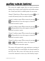
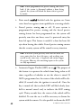
➜ Adjusting the Shock Sensor Setting
note: When adjusting the shock sensor, ensure that the
vehicle’s doors are closed.
1. Increase Sensitivity—Press and release the
button to
increase shock sensor sensitivity by one step. The siren and
remote will emit 2 chirps for each step increased in adjustment (and/or 1 vibrate if programmed). When the shock
sensor adjustment reaches maximum sensitivity when the
indicator
bar
is
filled
completely
to
the
right
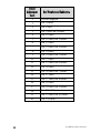
. There are 21 levels of shock sensor
adjustment, during sensor adjustment these levels are
displayed on the indicator bar as listed below.
note: When the arm and disarm are programmed to a single button, then the AUX button is used to increase the
sensitivity setting of the sensor.
© 2006 directed electronics
31
Sensor
Adjustment
Level
0
1
2
3
4
5
6
7
8
9
10
11
12
13
14
15
16
17
18
19
20
32
Bar Number and Indication
no bars displayed
bar 1 flashes
bar 1 solid
bar 1 solid, bar 2 flashes
bar 1-2 solid
bar 1-2 solid, bar 3 flashes
bar 1-3 solid
bar 1-3 solid, bar 4 flashes
bar 1-4 solid
bar 1-4 solid, bar 5 flashes
bar 1-5 solid
bar 1-5 solid, bar 6 flashes
bar 1-6 solid
bar 1-6 solid, bar 7 flashes
bar 1-7 solid
bar 1-7 solid, bar 8 flashes
bar 1-8 solid
bar 1-8 solid, bar 9 flashes
bar 1-9 solid
bar 1-9 solid, bar 10 flashes
bar 1-10 solid
© 2006 directed electronics
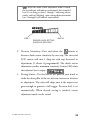
note: When the shock sensor adjustment mode is exited,
the bar indicator will indicate continuously. For example if
level 15 was being set (bars 1 through 7 indicating continuously, and bar 8 flashing), upon exiting adjustment mode
bars 1 through 8 will indicate continuously.
BAR 1
SENSOR LEVEL SETTING
SHOWN AT MID-POINT
BAR 10
2. Decrease Sensitivity—Press and release the
button to
decrease shock sensor sensitivity by one step. The siren and
LCD remote will emit 1 chirp for each step decreased in
adjustment (1 vibrate if programmed). The shock sensor
adjustment reaches minimum sensitivity (sensor Off ) when
the indicator bar is empty
.
3. Testing Sensor—Use the heel of the palm of your hand to
strike the door pillar of the car after any increase or decrease
in adjustment. The siren will chirp once if the impact was
great enough to generate a full trigger. Pre-warn level is set
automatically. When desired setting is reached, sensor
adjustment mode can be exited.
© 2006 directed electronics
33
➜ Exit Shock Sensor Adjustment Mode:
The adjustment mode will be exited if:
➤ No input from transmitter for 15-seconds.
➤ No input from sensitivity testing for 15-seconds.
➤ The ignition is turned On.
➤ The Valet button is pressed.
The siren and LCD remote will emit 1 long beep and the
vehicle’s LED will extinguish when shock adjustment mode is
exited.
➜ Reset Shock Sensor to Default Setting:
The shock sensor can be restored to a default setting of 10 to
facilitate re-adjustment at any time while in adjustment mode.
1. Simultaneously press the
and
buttons.
2. The siren and LCD remote will emit 3 quick beeps to indicate the sensor has been reset to level 10 (mid-range).
3. The system returns to shock sensor adjustment mode for
further adjustment, if required.
34
© 2006 directed electronics
diagnostics
The microprocessor at the heart of your security system is
constantly monitoring all of the switches and sensors that are
connected to it. It detects any faulty switches and sensors and
prevents them from disabling the entire system. The microprocessor will also record and report any triggers that occurred
during your absence. Refer to the System Status Chirps and Table
of Zones charts for diagnostic information.
➜ arming diagnostics
If the system is armed while an input is active (door open, sensor
triggering, etc.) the unit will chirp once when arming and then
one more time a few seconds later. This is called Bypass
Notification.
note: Bypass Notification will not occur when using
Silent Mode™ or if chirps have been programmed OFF.
The security system will ignore the input that was active when
the system was armed, until the input goes away. Three seconds
later the system will monitor that input normally. For example,
if your vehicle has interior light exit delay, and you arm the
system before the interior light goes out, you may hear Bypass
Notification chirps. Once the light shuts off, however, the doors
are monitored normally.
© 2006 directed electronics
35
➜ disarming diagnostics
Extra disarm chirps are the Tamper Alert. If four chirps are heard
when disarming, the system was triggered in your absence. If five
chirps are heard, a zone was triggered so many times that Nuisance
Prevention® Circuitry has bypassed that zone (see NPC section of
this guide). The in-vehicle status LED will indicate which zone was
involved. (See Table of Zones section of this guide.) The system will
retain this information in its memory, and continue to chirp four
or five times each time it is disarmed, until the next time the ignition key is turned on.
➜ system status chirps
The siren will chirp when arming/disarming the system. The
pattern of chirps will audibly report the system’s status as
described below.
Action
36
Number of Chirps
Description
Arm
1
System armed
Arm
1 (3-second delay), 1
System armed with
Bypass Notification
Disarm
2
System disarmed
Disarm
4
System disarmed with
Tamper Alert
Disarm
5
System disarmed NPC®
active
© 2006 directed electronics
➜ table of zones
The zone number is the number of LED flashes used by the
system to identify that input. The standard input assignments
are listed below, along with spaces to write in any optional
sensors or switches you have had installed.
Zone - Number
of LED Flashes
Description
1
Instant trigger - often used
for trunk pinswitches
2
Shock sensor input - a light
impact activates warn away
and a heavier impact activates
full alarm.
3
Door switch trigger
4
Optional sensor inputs for
warn away and full
alarm notification.
5
Ignition trigger
6
Hood trigger
7
Optional sensor inputs for
warn away and full
alarm notification.
© 2006 directed electronics
Dealer-Installed
Options
37
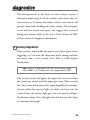
➜ interpreting zone diagnostics
Warn Away responses are not reported by arming or disarming
diagnostics. If you receive a Bypass notification when arming or
a Tamper Alert notification when disarming, look at the invehicle status LED. Active or triggered zones will be indicated by
a pattern of blinks by this LED.
Example
If Zone 3 was active or triggered, the in-vehicle LED will blink
three times with a two-second pause. Then it will blink three
times again, and repeat until the ignition is turned on.
note: Your system stores the last six triggered zones in
memory. If your system has been triggered but the LED
has been reset by turning on the ignition, your dealer can
still recall the last six zones that were triggered. Contact
your dealer for details.
code hopping
The receiver and transmitters each use mathematical formulas
called algorithms to change their codes each time the transmitter
is used. This technology has been developed to increase the security of the unit. The control unit knows what the next codes
should be. This helps to keep the transmitter "in sync" with the
control unit even if you use the remote control out of range of
the vehicle. However, if the transmitter has been pressed many
times out of range of the vehicle, or if the battery has been
removed, it may get out of sync with the control unit and fail to
operate the system. To re-sync the remote control simply press
38
© 2006 directed electronics
of the transmitter several times within range of the vehicle.
The alarm will automatically re-sync and respond to the transmitters normally.
owner recognition
Owner Recognition is a feature available exclusively from Directed.
Using the Directed Bitwriter®, a hand-held programming tool,
your dealer can program many of the system settings. The
programmer makes it possible to program different settings for
each transmitter that is used with the system. Then, whenever a
specific transmitter is used, the system will recall the settings
assigned to that transmitter. Owner Recognition lets up to four
users of the system have different settings that meet their specific
needs. It is almost like having four separate alarms in your vehicle,
one for each user.
note: Owner Recognition cannot be programmed without a Directed Bitwriter® and the necessary software.
Check with your dealer for more information.
rapid resume logic
This Directed system will store its current state to non-volatile
memory. If power is lost and then reconnected, the system will
recall the stored state from memory. This means if the unit is in
© 2006 directed electronics
39
Valet Mode and the battery is disconnected for any reason, such
as servicing the car, when the battery is reconnected the unit will
still be in Valet Mode. This applies to all states of the system
including arm, disarm, VRS®, and Valet Mode.
power saver mode
Your system will automatically enter Power Saver Mode while
armed or in Valet® Mode, after a period of time in which no
operation has been performed. This lowers the current draw to
the vehicle’s battery. Power Saver Mode takes over under the
following conditions:
➤
Power Saver when the system is armed: After the system has
been armed for 24 hours, the in-vehicle LED will flash at
half its normal rate, decreasing the system's current draw.
➤
Power Saver in Valet® Mode: When the system enters Valet®
Mode the in-vehicle LED illuminates steadily. If the vehicle
is not used (ignition is not turned on) for a period of one
hour while the system is in Valet® Mode, the LED will shut
off. If the system remains in Valet® Mode, the LED will
come back on the next time the ignition is turned on and
then back off.
40
© 2006 directed electronics
programming
Programming options control what your system does during
normal operation, and require few or no additional parts.
However, some may require additional installation labor.
The following is a list of the program settings, with the factory
settings in Bold:
➤
➤
➤
➤
Active arming (only with the remote) or passive arming (automatic arming 30-seconds after the last door has been
closed).
Arming/disarming confirmation siren chirps on or off.
The ignition controlled door lock feature on or off: With
this feature on, the doors will lock three seconds after the
ignition is turned on, and the doors are closed, and unlock
when the ignition is turned off. The system will not lock the
doors when the ignition is turned on with any door open.
The bitwriter is not needed to program theses separately, it
should be in the programming grid to do these 2 independently. Ignition lock and unlock are independent features
and can be programmed separately.
Passive door locking (with passive arming) or active door
locking (only when arming with the remote). Passive locking
allows the vehicle's doors to lock when the security system
passively arms (after the 30 second countdown). This feature
only works if passive arming has been programmed.
© 2006 directed electronics
41
note: When programmed for passive arming and active
lock, if the system is disarmed without a door being
opened, the system will relock the doors when it passively rearms.
➤
Panic mode enabled/disabled with the ignition on: Some
states have laws against siren capability in a moving vehicle.
➤
Forced passive arming on or off: If your system is
programmed for passive arming and the forced passive
arming feature has been programmed on, the system will
passively arm after one hour, even if a protected entry has
been left open. This feature is useful if a door has been left
ajar when leaving the vehicle. Forced passive arming ensures
that the security system will be armed in every situation.
note: When the system passively arms after one hour, the
entry point that has been left open, and anything connected to the same zone, is bypassed and cannot trigger
the system. However, the remaining inputs to the system
are fully operational.
➤
Automatic Engine Disable (AED) on or off: The purpose of
this feature is to protect the vehicle from being stolen at all
times, regardless of whether or not the alarm is armed. If
AED is programmed on, the starter of the vehicle will be disabled 30 seconds after the ignition is turned off. Once the
key is turned off, the in-vehicle LED will flash slowly (onehalf its normal armed rate) to indicate the AED arming
cycle. Thirty seconds later, the starter of the vehicle will be
disabled. To start the car, it will be necessary to disarm the
system with the remote. It is also possible to disarm the AED
42
© 2006 directed electronics
feature by turning the ignition key to the RUN position and
pressing the Valet® button the programmed number of
times. AED is disabled when the system is in Valet® Mode.
note: This feature will only function if the Failsafe®
Starter Kill relay has been installed.
➤
Full trigger response 30 or 60 seconds: This determines how
long the full triggered sequence lasts. Some states have laws
regulating how long a security system can sound before it is
considered a nuisance. If your installer is programming the
security system with the Directed Bitwriter, the full triggered
response can be programmed for any duration ranging from
1 to 180 seconds.
➤
Nuisance Prevention® Circuitry on or off: Please refer to the
NPC® section of this manual for a complete explanation of
how NPC® operates. If NPC® is programmed off, the security system will respond to inputs from any sensor indefinitely.
note: Because many states have laws regulating security
systems, programming NPC® off may cause your system
to violate state laws.
© 2006 directed electronics
43
➤
Progressive door trigger on or off: When the system is armed
and a door is opened, the system responds with ten chirps
prior to beginning the full triggered sequence. If an instant
trigger is desired, the progressive door trigger can be programmed off.
➤
Valet® pulse count: The number of presses of the Valet®
button required to disarm the security system, AED, or the
VRS® system can be programmed from one to five presses. The
default setting is one press.
➤
Siren tones and chirp volume: The output of the Revenger®
Soft Chirp® siren consists of six different tones in sequence.
Any of these tones can be eliminated by your dealer, resulting in a unique, easily identifiable siren sound. The siren
chirps can be either full volume or six decibels quieter than
the full alarm blast.
44
© 2006 directed electronics
installation options
The system has many options that may require extra parts and
labor. Some of the possibilities are listed here.
➤
Progressive unlocking: In most cars with electric power door
locks, the system can be configured so that when the system is
disarmed, only the driver’s door unlocks. A second press of the
button unlocks the other doors.
➤
Vehicle Recovery System (VRS®): VRS® is an anti-carjacking
device designed to help in the safe recovery of your vehicle
in case of a carjacking. Please refer to the Vehicle Recovery
System section of this guide for a complete explanation of
how the Vehicle Recovery System operates.
®
vehicle recovery system (vrs )
The optional VRS® feature is designed to ensure that any unauthorized user of your vehicle (even if using your keys and remote control)
will not be able to permanently separate you from your vehicle.
The VRS® cannot prevent a carjacking attempt; however, it does
ensure that if your vehicle is taken by an unauthorized user, it will
be disabled (after several progressive warnings) as safely as
possible. Should a carjacking occur, the VRS® allows you to
concern yourself with your personal safety without worrying
about your property.
© 2006 directed electronics
45
Directed has engineered this vehicle security system, the Failsafe®
Starter Kill, and the VRS® feature to provide the best combination of personal safety and property protection available. When
properly installed, the system can never inadvertently stop your
vehicle in traffic or on railroad tracks while the vehicle is in operation. It is unlike other systems that shut down your engine
while it is running. This system is designed to perform starter interrupt, or starter kill. The Failsafe® Starter Kill cannot shut
down an already-running engine – it can only prevent an engine
from starting in the first place.
important! Any installation that allows this product to
shut down a vehicle's engine when it is running is contrary to the product’s design and intended usage, and
Directed hereby expressly disclaims any liability resulting
therefrom.
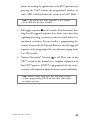
➜ arming the vrs®
To arm the VRS®, turn the ignition to the ON position and press
the arm button on the remote transmitter for one second. The
parking lights will flash and the siren will chirp once. This can be
done before driving or while driving the vehicle. Once the system
is armed, it will initiate its triggered sequence (see below) if any
door is opened and closed. If you are forced from the vehicle, the
system will trigger as the door is opened and closed. This is how
the system works to combat intersection carjacking. To protect
against parking lot carjacking, arm the VRS® before leaving the
vehicle. The system will now trigger automatically the next time
you or anyone drives the vehicle. This helps to protect the vehicle
46
© 2006 directed electronics
if someone takes your keys and remote transmitter by force in a
parking lot.
note: If the VRS® system is armed while operating the vehicle and not disarmed prior to leaving the vehicle, it is still
armed and will trigger the next time the vehicle is driven.
➜ vrs® triggered sequence
Fifteen seconds after the last door has closed, the in-vehicle LED
will begin flashing. This delay is intended to allow you time to
distance yourself from your vehicle in the event of a carjacking.
Forty-five seconds later, the siren begins chirping and the park-
ing lights begin flashing. This time could be used to notify authorities that your vehicle has been hijacked, and tell them what
the VRS® will do next.
Fifteen seconds after the siren chirps begin, the siren’s output will
change to a continuous blast.
From this point on, when the ignition key is turned off, the VRS®
will immediately turn on the starter kill. This will prevent the
vehicle from being restarted, thus immobilizing it at that spot.
Three minutes after the constant siren output begins, the flashing
parking lights and the siren will stop. The starter kill will remain
active until the system is disarmed. If the door is opened or the
ignition is turned off and on in an attempt to restart the car, the
siren and light flashing will begin again.
© 2006 directed electronics
47
➜ disarming the vrs®
Take the time to familiarize yourself with the VRS® triggering sequence and the disarm procedure. It is important to recognize
and identify the VRS® trigger sequence and know how to disarm
it in case of accidental activation.
Once the VRS® is armed, it does not disarm automatically. You
must disarm it the next time you operate the vehicle. You must
disarm it with one of the following procedures:
If the system has not entered the triggered sequence (siren has
not started chirping):
1. Turn the ignition on.
2. Press
on the transmitter for one second. The
lights will flash and the siren will chirp twice.
If the system has entered the triggered sequence (siren has begun
chirping), pressing the disarm button of the transmitter will not
disarm VRS®. To disarm the VRS® during a VRS® trigger sequence:
1. Turn the ignition on.
2. Press the Valet button the preprogrammed number of times to
DRW-35
disarm the VRS® system.
note: If the VRS® system has begun its chirping sequence,
the ignition must be turned off, then on to disarm. If you
are driving the vehicle at the time, pull to a safe place
away from traffic and follow the triggered sequence disarm procedure.
48
© 2006 directed electronics
programming options
See your dealer for further details on the options listed below
available with this system.
Automatic Engine Disable: Prevents the vehicle from being started
even if the vehicle is not armed after turning the ignition Off and
exiting the vehicle.
Comfort Closure: Windows will close upon locking the vehicle.
Dual Sensor Trigger: If programmed On both the onboard and at
least one of the optional sensors need to be triggered within 1second of each other for full alarm.
note: In dual sensor mode, the LCD remote will report
showing both zones that tripped the alarm. The in-vehicle
LED will flash to indicate only the last sensor of the pair
which tripped the alarm.
Forced Passive Arming: If passive arming is on and a door is left
open the system will be armed after 30-seconds.
High Security Disarm:
If the system is triggered this feature allows
the user to silence the siren and reset the system to the armed
state without having to visually check the system status.
Multi-level Arming: Allows bypassing of user selected alarm zones
of the vehicle.
Grouped Arming: Allows bypassing of the group of alarm zones
for warn-away, or both warn-away and full alarm of the vehicle.
© 2006 directed electronics
49
Panic with Ignition Off: Prevents the Panic button on the remotes from
activating panic with ignition On (not allowed in some states).
Parking Light Supervision: The parking lights will illuminate for
30-seconds after disarming the system or turning the ignition off.
Remote Start Reporting: This channel 3 program option allows
bypass of the security inputs that would trigger an alarm when
activating an added optional remote start system, but still retains
a high level of security.
Retained Accessory Power: This output from the security system
can be connected to vehicle accessories. After the ignition has
been turned off, it will continue to supply power until a door
has been open and closed.
security & convenience expansions
Here we have listed only some of the many expansion options
available. Please contact your dealer for a complete explanation
of all the options available to you.
Audio Sensor: Metal on glass, glass cracking, and breaking glass
each produce distinctive acoustic signatures. The 506T audio
sensor uses a microphone to pick up sounds, and then analyzes
them with proprietary acoustic software to determine if the glass
has been struck.
Backup Battery: The 520T keeps the system armed, triggers the
50
© 2006 directed electronics
alarm and keeps the starter kill active if main battery power is
disconnected.
Field Disturbance Sensor: An invisible dome of coverage is estab-
lished by installing the 508D "radar" sensor. Your security
system can then react to any intrusions into this field with the
triggered sequence.
Garage Door: Remote control of your system can go beyond
your vehicle. You can also control your automatic garage door
using the 519H2 garage door opener with your remote control.
Ask you dealer for details. Additional parts and labor required.
Headlight and Parking Light Automation: The 545T Nite-Lite®
will automatically turn on your parking and headlights when it
gets dark. In addition, the 545T will turn your headlights on
whenever the windshield wipers are used. A transmitter function
can also be used to turn on your parking and headlights for a
programmed time.
Power Trunk Release: The channel two output of the system can
operate a factory power release for the vehicle’s trunk or hatch.
(An additional relay may be required.) If the factory release is not
power activated, then Directed's 522T trunk release solenoid can
often be added.
Power Window Control: Automatic power window control is pro-
vided with the 529T and 530T systems.
Tilt Sensor: The 507M tilt sensor can be added to your system
© 2006 directed electronics
51
to protect your car when its parked. It can protect your vehicle
from being lifted to protect your expensive rims.
Valet Start System: For the ultimate in convenience, the Valet
start system can start your vehicle, monitor engine functions,
and power your climate control system with a push of a button.
Over-rev protection, open-hood lockout, brake pedal shutoff,
and automatic timer shutoff are all included. (This feature is
only for automatic transmission, fuel-injected vehicles.)
Ultrasonic Sensor: Providing a field of protection inside your car
using the 509U Ultrasonic sensor to protect your belongings.
52
© 2006 directed electronics
glossary of terms
ASK Amplitude Shift Keying—a method of transmitting data.
Control Unit: The "brain" of your system. Usually hidden under
the dash area of the vehicle. It houses the microprocessor which
monitors your vehicle and controls all of the system's functions.
Fail Safe Starter Kill: An automatic switch controlled by the secu-
rity system which prevents the vehicle’s starter from cranking
whenever the system is armed. The vehicle is never prevented
from cranking when the system is disarmed, in Valet mode, or
should the starter interrupt switch itself fail. Your system is ready
for this feature, however installation may require additional labor.
Input: A physical connection to the system. An input can be
provided by a sensor, pinswitch or through an existing system in
the vehicle, such as ignition or courtesy lights.
In-vehicle status LED: A light mounted somewhere in the vehicle.
It is used to indicate the status of your system. It is also used to
report triggers and faults in the system or sensors.
LCD: This is a Liquid Crystal Display used on your remote trans-
mitter to display your vehicles status/alarm information.
Shock Sensor: This is a sensor mounted in the vehicle that is
designed to pick up impacts to the vehicle or glass.
Siren: Noise generating device usually installed in the engine
compartment of the vehicle. It is responsible for generating the
© 2006 directed electronics
53
"chirps" you hear, as well as the six tones you hear while the
alarm is triggered.
Transmitter: Hand-held, remote control which operates the
various functions of your system.
Trigger or Triggered Sequence: This is what happens when the
alarm "goes off" or "trips". The triggered response of your
system consists of the siren sounding and parking light flashing
for the programmed duration.
Valet Button: A small push-button switch mounted somewhere
inside the vehicle. It is used to override the alarm when a transmitter is lost or damaged, or to enter or exit Valet mode.
Warn Away® Response: Lighter impacts to the vehicle will generate
the Warning Zone response. It consists of several seconds of siren
chirps and parking light flashes.
Zone: A zone is a separate input that the alarm can recognize as
unique. Each input to the system is connected to a particular
zone. Two or more inputs often share the same zone.
54
© 2006 directed electronics
✂
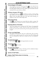
QUICK REFERENCE GUIDE
To arm using your LCD remote
Cut along dotted line and fold for a quick and easy reference to keep in your purse or wallet.
➤
You can activate, or arm, the system by pressing
on your remote for one
second. When the system arms, you will hear a short siren sound, or chirp, and
the parking lights will flash once. If the vehicle’s power door locks have been
connected to the system, the doors will lock.
To disarm using your LCD remote
➤
To disarm the system, press
. You will hear two chirps, and the parking
lights will flash twice. If power locks are connected to the system, the doors will
unlock. If the siren chirps either four or five times when disarming, see
Diagnostics section. This is called Tamper Alert.
Arming while driving
➤
Press
on your remote for two second while the vehicle is running. The
system will chirp once and then once more to indicate that the ignition is on.
Disarming without a LCD remote
➤
Turn on the ignition. Press and release the Valet® button the programmed
number of times within 15 seconds. After five seconds, the system will disarm.
If it does not, you may have waited too long. Turn the ignition off and on and
try again.
To enter or exit Valet® Mode
➤
Turn ignition to RUN position, then turn to OFF position. Press and release
the Valet® button within 10 seconds. The in-vehicle status LED will light solid
if you are entering Valet® Mode, and it will go out if you are exiting Valet®
Mode.
To activate Panic Mode
➤
Press and hold
or
down for approximately two seconds.
To exit Panic Mode
➤
Press
or
on the remote.
To activate Silent Mode™
➤
Press
briefly before arming or disarming, and the confirmation chirp(s)
will be eliminated for that one operation only.
✂
Location of Valet® Button_______________________________
Number of Valet® Button pulses for disarming_____________
© 2006 directed electronics
55
The company behind this system is Directed Electronics
Since its inception, Directed has had one purpose, to provide consumers with the
finest vehicle security and car stereo products and accessories available. The recipient
of more than 20 patents in the field of advanced electronic technology, Directed is
ISO 9001 registered.
Quality Directed Electronics products are sold and serviced throughout North America
and around the world.
Call (800) 274-0200 for more information about our products and services.
Directed® is committed to delivering world class quality products
and services that excite and delight our customers.
Directed Electronics
Vista, CA 92081
www.directed.com
© 2006 Directed Electronics. - All rights reserved
G3302X 11-06