1
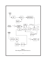
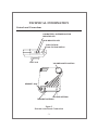
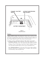
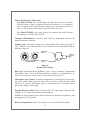
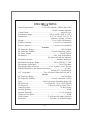
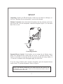
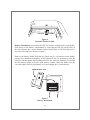
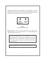
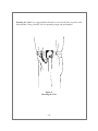
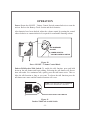
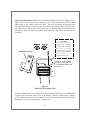
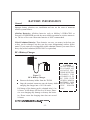
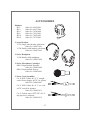
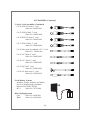
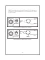
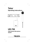
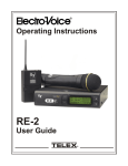
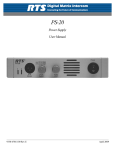
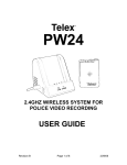
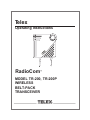
Telex TE LE X Operating Instructions RadioCom MODEL TR-200, TR-200P WIRELESS BELT-PACK TRANSCEIVER Table of Contents Page INTRODUCTION .......................................................................................................1 General Description ...............................................................................................1 Block Diagram...................................................................................................2 TECHNICAL INFORMATION ..................................................................................3 Controls and Connections......................................................................................3 Features ..................................................................................................................4 Volume ON/OFF Control..................................................................................4 Low Battery and Over Modulation Indicator LED ......................................... 4 Push-To-Talk/Lock-To-Talk Switch .................................................................5 Transmit LED Indicator ....................................................................................5 Headset Jack ......................................................................................................5 Belt Clip.............................................................................................................5 Microphone Gain Control..................................................................................5 Dynamic/Electret Switch ...................................................................................5 Battery Compartment.........................................................................................5 SPECIFICATIONS ......................................................................................................6 SET-UP ........................................................................................................................7 Unpacking ..............................................................................................................7 Headset Connection ...............................................................................................7 Dynamic/Electret Switch .......................................................................................7 Battery Installation.................................................................................................8 Battery Check ........................................................................................................9 Battery Removal ....................................................................................................9 Dressing the Unit.................................................................................................10 OPERATION .............................................................................................................11 Power ...................................................................................................................11 Push-to-Talk/Lock-to-Talk Switch......................................................................11 Adjusting Microphone Gain ................................................................................12 BATTERY INFORMATION .....................................................................................13 General.................................................................................................................13 Alkaline Batteries ............................................................................................13 Nickel-Cadmium Batteries ..............................................................................13 BC-4 Battery Charger......................................................................................13 FCC INFORMATION ...............................................................................................14 RECOMMENDED HEADSETS...............................................................................14 ACCESSORIES.........................................................................................................17 WARRANTY SERVICE INFORMATION...............................................................20 -i- INTRODUCTION General Description The Telex Model’s TR-200 and TR-200P Belt-pack Transceivers, are designed with one transmit and one receive channel and will operate on selected frequencies within the 150 to 216 MHz band. The TR-200 Transceiver operates in the continuous transmit mode with the audio, or talk, activated by a switch. As many as four TR-200 belt-pack transceivers can operate in a fully duplex network with one Telex Model BTR-200 or BTR-200 II Base Station. The TR-200P Transceiver operates in the Push-to-Transmit mode (the transmit and talk function are activated together). Any number of TR-200P transceivers can be used in a half-duplex network with one BTR-200 or BTR-200 II Base Station. Operate only one transmitter at a time. Attempting to use two transmitters simultaneously on the same channel will cause interference. Both the TR-200 and TR-200P can be configured to operate with another TR-200 or TR-200P. The receiver portion of the TR-200 and TR-200P consists of a crystal controlled dual conversion superheterodyne design. The transmitter portion of the TR-200 and TR-200P consists of a crystal controlled multiplier/amplifier design. -1- Figure 1 Block Diagram of TR-200 Transceiver -2- TECHNICAL INFORMATION Controls and Connections LOW BATTERY / OVERMODULATION INDICATOR LED TALK INDICATOR LED PUSH-TO-TALK/ LOCK-TO-TALK SWITCH BELT CLIP VOLUME ON/OFF CONTROL R HEADSET JACK RECEIVE ANTENNA TRANSMIT ANTENNA Figure 2 External controls and Connections -3- DYNAMIC / ELECTRET SWITCH FCC ID: B5DTR200 S/N: P / N : 7 0 6 8 1- E ACCESS TO MICROPHONE GAIN CONTROL D BATTERY COMPARTMENT Figure 3 Internal Controls Features Volume ON/OFF Control: This thumbwheel control serves as both an on/off switch and as a volume control. The transceiver is turned off when the control is in the extreme counterclockwise position, when viewed from the front, and the volume is loudest when the control is in the extreme clockwise position. Low Battery and Over Modulation Indicator LED: (labeled “bat/ovmod”) Low Battery Indicator: Part of the battery check circuit. When the volume ON/OFF Control is placed in the “ON” position the LED will flash one time if the battery is good. A poor battery will cause the LED to illuminate continuously and a bad or unusable battery will not cause any illumination at all. Over Modulation Indicator: Uses the same LED as the low battery indicator. During the transmit mode if microphone gain is too high the LED will illuminate when talking. Adjust microphone gain. -4- Push-to-Talk/Lock-to-Talk Switch: For Model TR-200, this switch enables the talk function. Press the button and hold down as long as required (Push-to-talk function), or if continuous talk is required (lock-to-talk function), quickly press the button two times to lock on. To release the talk function, press the button one time. For Model TR-200P, this switch enables the transmit and audio function and operates as described for TR-200. Transmit LED Indicator: (Labeled “talk”) Will be illuminated whenever the transmit function is enabled. Headset Jack: 4 Pin XLR Connector for Input/Output. The headset jack will accept 5 different Telex Model headsets and 1 handset. See Recommended Headsets starting on Page 14. MICROPHONE SHIELD (-) 4 1 2 MALE CONNECTORS BTR-200/TR-200 HEADPHONE BALANCED AUDIO OUT 3 MICROPHONE AUDIO (+) Figure 4 Headset Jack Wiring Belt Clip: Combination Belt Clip/Battery Cover. Access to Battery Compartment, Microphone Gain Control and Dynamic/Electret Switch is accomplished by removal of belt clip via a quick release 1/4 turn fastener.(See Page 8) Microphone Gain Control: Screwdriver adjustable by removing belt clip and prying out the small rubber plug to the right of the screw boss. Adjust the gain control clockwise to increase microphone gain or counterclockwise to decrease microphone gain. Replace rubber plug. Dynamic/Electret Switch: Place switch towards “D” when using a Dynamic Microphone or “E” when using an Electret Microphone. NOTE: All Telex headsets used with this intercom are dynamic microphones. Unit is shipped in the “D” position. Battery Compartment: Holds 6 AA batteries in a removable battery holder. -5- SPECIFICATIONS Overall Power Requirements....................6 AA cells (Alkaline, NEDA, MN 1500) Nickel Cadmium Optional Current Drain..........................................................................typical 65 mA Temperature Range ......................................-4°F to 130°F (-20°C to 55°C) Dimensions.....................................................4.25" W x 4.125" H x 2.0" D (108mm x 105mm x 51mm) Weight ................................................................13 oz (369g) with batteries Transmit Antenna ..................................................1/4-wave wire (attached) Receive Antenna....................................................1/4-wave wire (attached) Transmit RF Frequency Range ..............................................................150-216 MHz RF Frequency Stability .....................................Crystal Controlled, 0.005% RF Power Output..................................................................50 mW Typical Modulation ..............................................................FM, 5000 Hz deviation, 100 micro-seconds Pre-emphasis Modulation Limiter.......................................................Internal Compressor Modulation Frequency Range ................................300 to 5000 Hz +/-2 dB Microphone Audio Input....................................................30 to 3500 ohms Microphone Input Sensitivity ......................2 mV Dynamic, 4 mV Electret Radiated Harmonics and Spurious Emissions................................-45 dBC, Exceeds FCC Specifications FCC Acceptance ..............................Type Accepted Under Parts 90 and 74 Receive RF Frequency Range ..............................................................150-216 MHz RF Frequency Stability .....................................Crystal Controlled, 0.005% Type ................................................Dual Conversion Superheterodyne, FM RF Sensitivity ......................................Less than 0.5 µV for 12 dB SINAD IF Selectivity .............................................3 dB at 30 kHz (Ceramic Filter) Image Rejection ....................................................................70 dB or better Squelch Quieting..................................................................................90 dB Squelch Threshold..............................................................3.0 µV (internal) Signal-to-Noise Ratio ..........................................................................90 dB Audio Output............................................32 mW into 600 ohms (Headset) Distortion ......................................................Less than 1% at Rated Output -6- SET-UP Unpacking: Unpack your TR-200 System. If there are any defects or shortages, refer to the “Warranty Service Information” section in this manual. Headset Connection: Insert the headset/microphone into the connector on the bottom of the unit. See the microphone connection diagram (Figure 4) if unit other than Telex is used. R TO HEADSET Figure 5 Connecting Headset Dynamic/Electret Switch: If the headset you are using has an Electret microphone, the dynamic/electret switch must be in the “E” position (Electret). This switch is accessible by removing the belt clip and removing the battery holder. A +5 volt bias is available at the microphone plug for electret use. If you are using a headset with a dynamic microphone, place the dynamic/electret switch in the “D” position (Dynamic). Refer to Figure 6. NOTE: FOR PROPER OPERATION YOU MUST MATCH THE TYPE OF MICROPHONE YOU ARE USING WITH THE DYNAMIC/ELECTRET SWITCH LOCATED INSIDE THE UNIT. -7- FCC ID: B5DTR200 S/N: P / N : 7 0 6 8 1- E ELECTRET D DYNAMIC Figure 6 Dynamic/Electret Switch Battery Installation: Assure that the OFF/ON Volume control knob is turned OFF. Gain access to the battery compartment by removing the belt clip on the back of the unit. Release the 1/4 turn fastener located on the back of the belt clip and remove the belt clip/cover. Refer to Figure 7. Remove the battery holder from the box. Insert six (6) AA batteries in the holder, paying close attention to polarities of the batteries.It may be necessary to turn the batteries with the thumb and forefinger the first few times the batteries are inserted into the battery holder to Assure good positive contact. Insert the holder into the case and replace the belt clip/battery cover and engage the 1/4 turn fastener. REMOVE BELT CLIP Figure 7 Battery Installation -8- Battery Check: Rotate the Volume ON/OFF Control knob clockwise to turn the unit on. Note that the battery LED (Labeled bat/ ovmod) should flash one time on good batteries. Poor batteries will cause the LED to be illuminated continuously and a bad or unusable battery will not cause any illumination at all. bat/ ovmod talk Figure 8 Low Battery Indicator LED Battery Removal: To remove the battery holder from the case to change batteries, follow the instructions as before for removing the cover. Pull the pull bale on the holder. The holder should come out. NOTE: For maximum uninterrupted service it is suggested that new 1.5 volt alkaline AA batteries (Mallory MN1500 or equivalent) be installed prior to each use. Avoid “shelf worn” or “economical” batteries. Operation from heavy duty nickel-cadmium batteries is also permissible, at the expense of operating time. (NEDA 10015 or equivalent). Typical life of fresh alkaline batteries with the TR-200 is approximately 24 hours maximum. 8-10 hours is typical of fully charged nickel-cadmium batteries. NOTE: Nickel-cadmium batteries can be charged right in the holder using the Telex BC-4 Battery Charger (P/N 70741000). Refer to Battery Information Section. -9- TE LE X Dressing the Unit: It is suggested that the unit be worn on the belt or pocket with both antenna’s hung vertically for best operating range and performance. Figure 9 Dressing the Unit -10- OPERATION Power: Rotate the ON/OFF - Volume Control Switch counterclockwise to turn the unit on. Refer to the Battery Check Section and check batteries. After batteries have been checked, adjust the volume control by rotating the control either clockwise or counterclockwise as required for comfortable listening volume. LE X ON/ INCREASES VOLUME TE POWER ON/OFF & VOLUME CONTROL SWITCH Figure 10 Power ON/OFF - Volume Control Knob Push-to-Talk/Lock-to-Talk Switch: To enable the talk function, press and hold down on the talk button and begin talking. Releasing the talk button will discontinue talk audio. For continuous talk, quickly press the talk button twice. This enables the talk function as long as you want. To release the talk function press the talk button once more and the transmit function will cease. NOTE: The talk LED will be illuminated whenever the talk function is activated. talk talk PUSH-to-TALK/LOCK-to-TALK SWITCH Figure 11 Push-to-Talk/Lock-to-talk Switch -11- Adjusting Microphone Gain: If the transmitted audio from the microphone is too high or too low, remove the belt clip on the rear of the unit and pry out the small rubber plug to the right of the screw boss. This will reveal the microphone gain control potentiometer. Using a plastic screwdriver (supplied), adjust the gain control clockwise to increase the microphone gain or counterclockwise to decrease the microphone gain. Reinstall the rubber plug and belt clip when adjustments are complete. CAUTION DO NOT remove this rubber plug or attempt to adjust. This beltpack has been precisely tuned and any attempt to alter this adjustment will result in a non-operational unit. REMOVE BELT CLIP REMOVE THIS RUBBER PLUG FOR ACCESS TO THE MICROPHONE GAIN CONTROL Figure 12 Adjusting Microphone Gain If the microphone gain is too high, the over modulation LED (the Over Modulation Circuitry uses the same LED as the Low Battery Circuitry [labeled bat/ ovmod]) will be illuminated when you are talking. Decrease the Microphone Gain until this illumination ceases when talking in a normal tone. -12- BATTERY INFORMATION General Improper battery selection, use, installation and care are the cause of numerous wireless system failures. Alkaline Batteries: Alkaline batteries such as Mallory’s DURACELL or Eveready’s ENERGIZER provide the most reliable operation in wireless transceivers. The use of low cost carbon-zinc batteries is NOT recommended. Nickel-Cadmium Batteries: These batteries can save you money in the long run, as they can be recharged, but they can also cause disappointing wireless performance. If you want to use rechargeable nickel-cadmium batteries you must select a heavy duty nickel-cadmium (NEDA 10015 or equivalent) BC-4 Battery Charger Figure 13 BC-4 Battery Charger · Remove the battery holder from the TR-200. · Snap the terminal connector onto the battery holder and plug the charger into a 110 Volt outlet. Full charge of the battery pack is obtained after 14 to 16 hours. A full charge will last 8 to 10 hours. Extensive over-charging may damage or destroy the batteries. Please assure the charging time does not exceed 16 hours. ENERGIZER® is a registered trademark of Union Carbide Corporation. DURACELL® is a registered trademark of Duracell Inc. -13- CAUTION DO NOT ATTEMPT TO CHARGE ANY ALKALINE BATTERIES WITH THIS CHARGER. THIS CHARGER IS TO BE USED WITH NICKEL CADMIUM BATTERIES USED IN THE TR200 BATTERY HOLDER ONLY. FCC INFORMATION The Telex Model TR-200 transceiver is Type Accepted under United States Federal communications Commission Parts 90 and 74. Licensing of Telex equipment is the user’s responsibility and licensability depends upon the user’s classification, user’s application, and frequency selected. Telex strongly urges the user to contact the appropriate telecommunications before ordering and choosing frequencies. CAUTION: Changes or modifications made by the user could void the user’s authority to operate the equipment. RECOMMENDED HEADSETS V-Series (See pages 17 and 18 for Ordering Information) Earphone Frequency Response ..........................................10 Hz - 20 kHz Earphone Input Sensitivity .................................................90dB @ 1 mW Microphone Frequency Response Dynamic (MB-11)...............................................50 Hz - 15 kHz ±3 dB Electret (MB-12) .................................................20 Hz - 20 kHz ±3 dΒ Microphone Input Sensitivity (re: 1 volt/µbar) Dynamic (MB-11) ........................................................................-87 dB Electret (MB-12) ..........................................................................-84 dB Impedance Earphones:...............................................................Mono 150 or 600 Ω Stereo 75 or 300 Ω Microphones ..................................................................................150 Ω Size H-W-D..........................8" (203 mm) x 9" (228 mm) x 4" (102 mm) Weight V-200 double-sided headphone..........................14 ounces (396 grams) V-210 single-sided headset .............................10.5 ounces (298 grams) V-220 double-sided headset .............................15.5 ounces 439 grams) -14- Recommended Headsets Continued PH-1 Catalog No..................................................................................64438-005 Earphone Type ...................................................................Dynamic/Single Earphone Impedance....................................................................150 ohms Earphone Frequency Response .............................................50-15,000 Hz Earphone Output ..............................................................................105 dB Microphone Type .............................................Dynamic Noise Cancelling Microphone Impedance ...............................................................150 ohms Microphone Frequency Response .........................................100-8,000 Hz Microphone Output ...................................-83 re: 1V/microbar (.071 mV) Cable Length.................................................................6 ft. (1.8 m) coiled Cable Connector ..........................................................Female XLR-4 type PH-2 Catalog No..................................................................................64437-006 Earphone Type...........................................................Dynamic/Dual/Mono Earphone Impedance....................................................................150 ohms Earphone Frequency Response .............................................50-15,000 Hz Earphone Output ..............................................................................105 dB Microphone Type .............................................Dynamic Noise Cancelling Microphone Impedance ...............................................................150 ohms Microphone Frequency Response .........................................100-8,000 Hz Microphone Output ...................................-83 re: 1V/microbar (.071 mV) Cable Length.................................................................6 ft. (1.8 m) coiled Cable Connector ..........................................................Female XLR-4 type PH-4 Catalog No..................................................................................70340-000 Earphone Type...........................................................Dynamic/Dual/Mono Earphone Impedance....................................................................150 ohms Earphone Frequency Response .............................................50-15,000 Hz Earphone Output ................................................................................98 dB Microphone Type .............................................Dynamic Noise Cancelling Microphone Impedance ...............................................................200 ohms Microphone Frequency Response .........................................50-10,000 Hz Microphone Output ...................................-89 re: 1V/microbar (.035 mV) Cable Length............................................................................5 ft. (1.5 m) Cable Connector ..........................................................Female XLR-4 type -15- Recommended Headsets Continued PH-8 Catalog No..................................................................................70415-001 Earphone Type....................................................................Dynamic/Mono Earphone Impedance....................................................................150 ohms Earphone Frequency Response .............................................50-15,000 Hz Earphone Output ................................................................................98 dB Microphone Type .............................................Dynamic/Noise Cancelling Microphone Impedance ...............................................................200 ohms Microphone Frequency Response .........................................50-10,000 Hz Microphone Output ...................................-89 re: 1V/microbar (.035 mV) Cable Length.................................................................5 ft. (1.5 m) coiled Cable Connector ..........................................................Female XLR-4 type PH-10 Catalog No..................................................................................70470-003 Earphone Type...........................................................Dynamic/Dual Mono Earphone Impedance....................................................................150 ohms Earphone Frequency Response .............................................50-15,000 Hz Earphone Output ..............................................................................105 dB Microphone Type .............................................Dynamic Noise Cancelling Microphone Impedance ...............................................................150 ohms Microphone Frequency Response .........................................100-8,000 Hz Microphone Output ...................................-83 re: 1V/microbar (.071 mV) Cable Length.................................................................6 ft. (1.8 m) coiled Cable Connector ..........................................................Female XLR-4 type PH-16 Catalog No. ...............................................................................70770-003 Catalog No. (Optional liquid filled cushions) ...........................70753-001 Earphone Type ..............................................................................Dynamic Earphone Impedance....................................................................150 ohms Earphone Frequency Response .............................................15-15,000 Hz Earphone Output ..............................................................................105 dB Microphone Type .............................................Dynamic Noise Cancelling Microphone Impedance ...............................................................150 ohms Microphone Frequency Response .........................................100-8,000 Hz Microphone Output.....................................-83 re: 1V/micobar (.071 mV) Cable Length.................................................................6 ft. (1.8 m) coiled Cable Connector ..........................................................Female XLR-4 type -16- ACCESSORIES Headsets PH-1 PH-2 PH-4 PH-8 PH-10 PH-16 Order Order Order Order Order Order No. No. No. No. No. No. 64438-005 64437-006 70340-000 70415-001 70470-003 70770-003 V-series Headsets V-210 Single sided headset with boom Order No. 300027-001 V-220 Double sided headset with boom Order No. 300027-002 V-Series Headphone V-200 Double sided headphone Order No. 300027-000 V-Series Microphone Cartridges MB-11 Supercardioid Dynamic Order No. 300028-000 MB-12 Supercardioid Electret Order No. 300028-001 V-Series Cord Assemblies CA-10 XLR-3 Male & 1/4" 5’ straight cord w/Power Supply & PTC for electret Order No. 300029-007 CA-11 XLR-3 Male & 1/4" 5’ str. cord w/PTC switch for dynamic Order No. 300029-011 CA-12 Carbon amp w/PTT/PTC & 1/4" ring-tip-sleeve connector Order No. 300029-012 -17- ACCESSORIES (Continued) V-Series Cord Assemblies (Continued) CA-20 XLR-4 Female 5’ cord Order No. 300029-001 CA-22 XLR-4 Male 5’ cord Order No. 300029-000 CA-30 XLR-5 Female 5’ cord Order No. 300029-009 CA-33 XLR-5 Male 5’ cord Order No. 300029-004 CA-40 Sony mini 4-conductor 1/8" 5’ cord Order No. 300029-006 CA-50 1/4" Mono 5’ cord Order No. 300029-005 CA-60 1/4" Stereo 5’ cord Order No. 300029-003 CA-70 Pig Tail 5’ cord Order No. 300029-002 CA-80 1/8 mini stereo 5’ cord Order No. 300029-010 Nicad Battery System: Includes; Charger, batteries and battery sled. For charging nickel-cadmium batteries used in the TR-200 BC-4 Order No. 70741-000 Belt Clip Replacement Gray Order No. 96605-001 Black Order No. 96605-000 -18- NOTE: This manual is also used for the RTS version 2110/2105 Intercom system which uses a different headphone jack. Use the illustrations below in place of Figure 4 of page5. MICROPHONE SHIELD (-) HEADPHONE BALANCED AUDIO OUT 1 4 2 3 4 1 3 2 MICROPHONE AUDIO (+) FEMALE CONNECTORS RTS 2110/2105 RTS 2110/2105 4-Pin Headset XLR Connector MICROPHONE SHIELD (-) HEADPHONE AUDIO OUT (MONO) 1 5 4 5 1 2 4 3 2 3 MICROPHONE AUDIO (+) FEMALE CONNECTORS RTS 2110/2105 HEADPHONE COMMON RTS 2110/2105 5-Pin Headset XLR Connector -19- CUSTOMER SERVICE INFORMATION If your receiver or transmitter should need servicing under the warranty, please contact: Customer Service Department TELEX COMMUNICATIONS, INC. 8601 East Cornhusker Highway, P.O. Box 5579, Lincoln, Nebraska 68505-5579 U.S.A. Phone: (402) 467-5321 or 465-7021 All claims of defect or shortage should be sent to the above address. When returning items for service, you must provide date and proof of purchase, such as a copy of the sales receipt, to establish warranty. A letter should be included outlining all symptoms and claimed defects. Information on how the equipment was installed and used is very helpful. Please include your phone number and return address in case our service technicians need to contact you. Units that have been modified cannot be accepted for repair. Include all information requested by the Service Department. Then pack the unit as follows: Check the unit to see that all parts and screws are in place. Then wrap it in heavy paper or put it in a plastic bag. If the original carton is not available, place the unit in a strong carton that is at least six inches bigger in all three dimensions than the unit. Fill the carton equally around the unit with resilient packing material (shredded paper, foam, etc.). Seal it with gummed paper tape, tie it with a strong cord, and ship it by prepaid express, United Parcel Service or insured parcel post to the Telex Service Department. It is very important that the shipment be well-packed and fully insured. Damage claims must be settled between you and the carrier and this can delay repair and return of the unit to you. Telex reserves the right to make changes in design and improvement on its product without assuming any obligation to install the same on any of its products previously manufactured. Further Telex reserves the right to ship new and/or improved products which are similar to the form, fit and function of products originally ordered. -20- TELEX COMMUNICATIONS, INC. 12000 Portland Ave. South, Bur nsville, MN 55337, U.S.A. MADE IN U.S.A. APRIL 1998 PN 802205-2