1
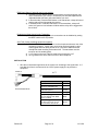
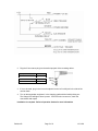
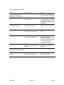
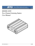
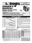
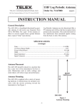
2.4GHZ WIRELESS SYSTEM FOR
POLICE VIDEO RECORDING
USER GUIDE
Revision B
Page 1 of 9
12/11/08
TABLE OF CONTENTS
1.
2.
3.
4.
5.
6.
7.
Revision B
Quick Set Up and Operation ....................................................... 3
Installation .................................................................................... 4
Guidelines For Best Performance ................................................ 6
Troubleshooting Guide................................................................. 7
Technical Specifications............................................................... 8
Service and Warranty................................................................... 9
Components and Accessories ..................................................... 9
Page 2 of 9
12/11/08
QUICK SET UP AND OPERATION
Synching Up The Transmitter and Base The synch operation only needs to be performed
the first time a system is used, or a new bodypack is used with a base previously synched to
another bodypack. Do not perform the synch operation multiple times; it only needs to
be done one time when a new bodypack is used with a new base.
1) Turn the transmitter power switch to ON and place the transmitter in the
recharge cradle of the base. The transmitter goes in the base with the
beltclip facing out.
2) The recharge LED will light (Green if fully charged, Red if charging). Leave
the transmitter in the cradle for 4 hours for a full charge.
3) Press the In-Use button on the transmitter and hold until the In-Use LED on
the transmitter and base start to flash, then release the button.
4) After a few seconds the light will stop flashing, and a beep will sound (If the
beep is enabled).
5) The transmitter and base are now synched and will continue to be until
another transmitter is linked to that base.
Normal Operation
1) With the transmitter synched up, remove it from the cradle, plug in the lapel
microphone (if used) and place the transmitter on your belt.
2) To start the recording, press the In-Use button and the In-Use LED will light a
constant green and you will hear a short beep
3) To end recording, press the In-Use button and the In-Use LED will turn off
and you will hear a short beep.
4) At the end of your shift turn the transmitter off and replace it in the charging
cradle.
Out of Range
1) If you use the Transmitter too far away from the Receiver during recording,
the transmitter will alert you with Audible warning beeps (two tone) and the
In-Use LED will blink in red.
2) Move closer to the receiver base and the link will be re-established once you
return to normal range. The In-Use LED will light constant green when link is
back to normal operation.
3) If the link is not re-established within 30 seconds, the transmitter and receiver
will return to standby mode.
4) If you went out of range in Standby mode, or the unit reverted to standby
mode, re-enter normal range and press the In-Use button. Operation will
return to normal.
5) If you will be out of range for a long period of time, turn the bodypack off.
Low Battery Warning
1) If the transmitter Low BATT indicator (red) starts flashing or you hear warning
beeps, return the transmitter to its cradle on the receiver to fully charge the
transmitter.
2) The Charge LED indicator will light constant green when the unit is fully
charged.
Revision B
Page 3 of 9
12/11/08
EMG Panic Button (if wired for use in your vehicle)
1) The EMG or Panic Button can be programmed to do many things but may
not be connected in your vehicle. Check with your technical department to
understand what this button will control before you use it.
2) In Record mode: Press the EMG button on the transmitter, a beep will sound
and the relay will be triggered at the receiver.
3) In Standby mode: Press the EMG button on the transmitter, a beep will
sound, the green In-Use indicator will blink and the relay will be triggered at
the receiver.
Disabling the Beep Sound On the Transmitter
1) All of the audible beep signals on the transmitter can be disabled by setting
the BEEP switch to the off position.
Auto Talk (if video recording equipment supports)
1) The Auto Talk feature is used to turn on the microphone whenever the video
recorder is turned on. Some video record units can be triggered by other
events (lights and siren being turned on etc.) and Auto Talk ensures the
microphone starts recording at the same time. The transmitter must be
turned on and in standby mode.
2) A +5V signal on the Auto Talk line means the microphone is off.
3) 0V or ground on the Auto Talk line turns on the microphone
INSTALLATION
1. Wire the un-terminated signal wires to the control unit according to the signal chart. A 5
Amp fast blow fuse is recommend in the 12VDC power supply line to protect the
equipment.
Audio In
Un-terminated wires
Revision B
12 FT
Description
Power +12V DC
Video Trigger
(Ground = Transmitter On)
Left Channel (Ground to enable
Inside Microphone)
Power Ground
AUX (Panic) Trigger
12V+ DC Output when EMG
button is pushed
Auto Talk Trigger
5V+ DC to 0V to turn on mic
0V to 5V+DC to turn off mic
Page 4 of 9
Color
Red
Blue
Yellow
Orange
Black
Brown
12/11/08
2. Plug the 3.5mm stereo plug into the audio input jack of the recording device.
Description
Position
Inside Car Mic Audio
Tip
Ring
Sleeve
Transmitter Audio
Audio Ground
Sleeve
Ring
Tip
3. If it is to be used, plug in the in-car microphone into the In-Car Mic jack in the side of the
receiver base.
4. Turn on the transmitter and place it in the charging cradle with the beltclip facing out.
The Charge LED will light if there is power. If the LEDs do not come on, check the
connections and repeat.
Installation is complete. Refer to Operation Section for more information.
Revision B
Page 5 of 9
12/11/08
4) Guidelines and recommendations for best performance.
Compatibility
The transmitter and receiver must synchronize to work together (see Synch process on page 3).
The synch operation only needs to be performed the first time a system is used, or when a new
bodypack is used with a base previously synched to another bodypack. Do not synch multiple
times, just once until a new bodypack is used. Any PR24N can be synchronized with any
PB24N base.
Using Multiple Wireless Systems
The PW24N system has 95 possible channels that are really different frequency hopping
schemes. Each synchronized base and transmitter will automatically find a clear channel so up
to 40 systems can work together in one location depending on other interference problems.
Potential Sources of Interference
There are many potential sources of interference for your wireless system. Any electronic
product that contains digital circuitry including digital signal processors (reverb/multi-effects units),
electronic keyboards, digital lighting controllers, CD and DVD players, and computers, all emit RF
energy that can adversely affect the performance of your wireless system. It is always best to
place the receiver as far away as possible from these devices to minimize potential problems.
The PW24N operates in the 2.4MHz ISM band and other devices in that band may interfere. The
spread spectrum technique used in the PW24N is very robust and should operate even in the
presence of other 2.4MHz devices such as walkie-talkies, LANs, cordless phones, etc. in the
area.
Battery Recommendations
The Lithium-Ion battery built into the PB24N transmitter will work at full capacity for over 500
charge cycles. If you notice lower than usual battery life over time, it may be time to replace the
cell.
Warnings
Do not use this product in or near water, i.e. near a bathtub, sink, or swimming pool.
Do not use this product in the vicinity of a gas leak or to report a gas leak.
Revision B
Page 6 of 9
12/11/08
5) Trouble Shooting Guide
Problem
No audio and no In-Use LED
light on the receiver when
transmitter is on and In-Use
Possible Causes
Receiver is not powered
Solutions
Make sure that the power
supply is properly connected
Transmitter and receiver not
synchronized
No (or low) Audio with all InUse LEDs solid green
Turn on transmitter and place
in recharge cradle. Press the
In-Use button until the In-Use
LEDs flash 3 and the pair will
be synched
Lapel Microphone not connected Check the mic connection and
or positioned properly
placement of the microphone
Receiver audio output cable is
damaged or disconnected
Connect, repair or replace
cable
Interference
Another 2.4GHz device in the
area causing interference.
Push the In-Use button twice
and the PW24N will
automatically select a clearer
channel. If the interference is
too strong, this may not
completely eliminate it.
Short range or drop-outs
RF reflective metal obstacles
between the transmitter and
receiver
Move the obstacles, or
reposition the receiver if
possible
In-Use LED on beltpack flashes Transmitter is out of range
red and two tone beep sounds
Move closer to the receiver.
Variable synch times or failure
to synch
Power cycle the base station
and Synch one time.
Revision B
Synch process run more than
one time with same pair
Page 7 of 9
12/11/08
PR24N RECEIVER BASE STATION
Controls
Video Trigger Active +12/GND
Indicators
IN-USE LED:
GREEN
CHARGE LED:
CHARGING -> RED
FULL CHARGED -> GREEN
Connections
In Car Mic
2.5mm Mono Plug
Un-terminated Cord
RED
+12V DC Power
BLUE
Microphone Trigger (Ground or 12VDC = Transmitter On)
BLACK
AUX (Panic) Trigger (+12V when EMG is pushed)
YELLOW
Left Channel (Inside Mic)
ORANGE
Power Ground
BROWN
Auto Talk (5V = mic off, 0V = mic on)
Audio Connector
Tip
Inside Car Mic
Ring
Transmitter Audio
Sleeve
Audio Ground
RF Specifications
Frequency Range:
2.4GHz
Number of Channels:
95 possible
Diversity:
Internal antenna
Receiver Type:
Fast Frequency Hopping
RF Sensitivity:
-102 +/-3 dBm(I,Q signal level at -3dB point))
FCC type acceptance: Approved under Part 15
Audio Specifications
Frequency Response: 200 ~ 4000Hz +/- 3 dB
Audio Output Level:
3.6Vp-p
Distortion:
Less than 2%
Signal to Noise Ratio: > 40 dB
Dynamic Range:
> 50 dB
General Specifications
Range
1000 feet typical in line of sight
Power Supply:
External 12 VDC
Current Draw:
190mA Typical
Size:
2.75in x 2.99in x 3.15in
70mm x 76mm x 80mm
Weight
233 g
PB24N Bodypack Transmitter
Controls
On/Off Switch
Beep On/Off Switch
In Use Button
Emergency Button
Indicators
Red LED
Yellow LED
Battery
Battery Life
Battery Recharge Time
Antenna
1.5mm Mic Connector
Secondary Microphone
RF Output
Size:
Weight
Revision B
low battery indicator/Emergency indicator
In Use
Internal Li-ion 3.7V/1200mAh cell
8 hours In Use with full charge
14days Standby
3.5 hours from full discharge
Internal
Tip
Signal, Sleeve
Ground
Internal
30 ~ 40 mW (typical)
2.5 in. x 1.8 in. x 0.94 in.
64 mm x 46 mm x 24 mm
74 g
Page 8 of 9
12/11/08
Factory Service (North America)
If factory service is required, ship the unit prepaid in its original carton to:
Telex Audio Service
c/o Telex Communications
8601 East Cornhusker Highway
Lincoln, NE 68507-9702 U.S.A.
Tel: 402/467-5321 or 800-553-5992
Fax: 402/467-3279
Enclose a note describing the problem along with any other pertinent information and how to contact you.
Warranty (Limited)
Telex products are guaranteed against malfunction due to defects in materials or workmanship for a specified period, as
noted in the individual product-line statement(s) below, or in the individual product data sheet or owner's manual,
beginning with the date of original purchase. If such malfunction occurs during the specified period, the product will be
repaired or replaced (at our option) without charge. The product will be returned to the customer prepaid via UPS Ground.
Exclusions and Limitations: The Limited Warranty does not apply to: (a) exterior finish or appearance; (b) certain
specific described in the individual product-line statement(s) below,
or in the individual product data sheet or owner's manual; (c) malfunction resulting from use or operation of the product
other than as specified in the product data sheet or owner's manual; (d) malfunction resulting from misuse or abuse of the
product; or (e) malfunction occurring at any time after repairs have been made to the product by anyone other than
Electro-Voice or any of its authorized service representatives.
Obtaining Warranty Service: To obtain warranty service, the customer must deliver the product, prepaid, to Telex
together with proof of purchase of the product in the form of a bill of sale or receipted invoice.
Incidental and Consequential Damages Excluded: Product repair or replacement and return to the customer are the
only remedies provided to the customer. Telex shall not be liable for any incidental or consequential damages including,
without limitation, injury to persons or property or loss of use.
Other Rights (United States Only): This warranty gives you specific legal rights and you may also have other rights,
which vary from state to state.
Telex 2.4GHz Wireless Systems are guaranteed against malfunction due to defects in materials or workmanship for a
period of one (1) year from the date of original purchase. The Limited Warranty does not extend to cables or cable
connectors. Additional details are included in the Uniform Limited Warranty Statement. Technical Assistance: 800-3923497(U.S. and Canada only)
ACCESSORIES AND PARTS
Police Wireless PW24N
Model
Part #
PB24N
PRD00018001
PR24N
TC-24
KT24-ML
PW24-MI
PRD00018000
302039004
302039007
302039005
Revision B
DESCRIPTION
Bodypack transmitter with internal microphone,
internal Li-ion battery cell, belt clip, no microphone
Receiver and recharge station, un-terminated
connection cable
Optional TX Charger Base for PB24N
Lapel Microphone for PB24N
In Car Microphone
Page 9 of 9
12/11/08