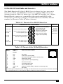
1
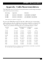
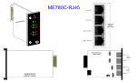
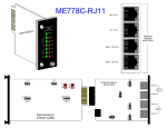
MAY 1995
ME758C-RJ11
ME758C-RJ45
ME759C-RJ11
ME759C-RJ45
Multi-Function LD Cards
Power
TD
RD
RTS
CD
Error
Test
Remote
511/E
CUSTOMER
SUPPORT
INFORMATION
Analog
511
Order toll-free in the U.S.: Call 877-877-BBOX (outside U.S. call 724-746-5500)
FREE technical support 24 hours a day, 7 days a week: Call 724-746-5500 or fax 724-746-0746
Mailing address: Black Box Corporation, 1000 Park Drive, Lawrence, PA 15055-1018
Web site: www.blackbox.com • E-mail: [email protected]
FCC STATEMENTS
FEDERAL COMMUNICATIONS COMMISSION
AND
INDUSTRY CANADA
RADIO FREQUENCY INTERFERENCE STATEMENTS
This equipment generates, uses, and can radiate radio-frequency energy, and if not
installed and used properly, that is, in strict accordance with the manufacturer’s
instructions, may cause interference to radio communication. It has been tested
and found to comply with the limits for a Class A computing device in accordance
with the specifications in Subpart B of Part 15 of FCC rules, which are designed to
provide reasonable protection against such interference when the equipment is
operated in a commercial environment. Operation of this equipment in a
residential area is likely to cause interference, in which case the user at his own
expense will be required to take whatever measures may be necessary to correct
the interference.
Changes or modifications not expressly approved by the party responsible
for compliance could void the user’s authority to operate the equipment.
This digital apparatus does not exceed the Class A limits for radio noise emission from
digital apparatus set out in the Radio Interference Regulation of Industry Canada.
Le présent appareil numérique n’émet pas de bruits radioélectriques dépassant les limites
applicables aux appareils numériques de la classe A prescrites dans le Règlement sur le
brouillage radioélectrique publié par Industrie Canada.
TRADEMARKS USED IN THIS MANUAL
AT&T is a registered trademark of American Telephone and Telegraph
Company.
Littelfuse is a registered trademark of Littelfuse, Inc.
Any other trademarks mentioned in this manual are acknowledged to be the property of the
trademark owners.
1
MULTI-FUNCTION LD CARD
NORMAS OFICIALES MEXICANAS (NOM)
ELECTRICAL SAFETY STATEMENT
INSTRUCCIONES DE SEGURIDAD
1. Todas las instrucciones de seguridad y operación deberán ser leídas antes de
que el aparato eléctrico sea operado.
2. Las instrucciones de seguridad y operación deberán ser guardadas para
referencia futura.
3. Todas las advertencias en el aparato eléctrico y en sus instrucciones de
operación deben ser respetadas.
4. Todas las instrucciones de operación y uso deben ser seguidas.
5. El aparato eléctrico no deberá ser usado cerca del agua—por ejemplo, cerca
de la tina de baño, lavabo, sótano mojado o cerca de una alberca, etc..
6. El aparato eléctrico debe ser usado únicamente con carritos o pedestales que
sean recomendados por el fabricante.
7. El aparato eléctrico debe ser montado a la pared o al techo sólo como sea
recomendado por el fabricante.
8. Servicio—El usuario no debe intentar dar servicio al equipo eléctrico más allá
a lo descrito en las instrucciones de operación. Todo otro servicio deberá ser
referido a personal de servicio calificado.
9. El aparato eléctrico debe ser situado de tal manera que su posición no
interfiera su uso. La colocación del aparato eléctrico sobre una cama, sofá,
alfombra o superficie similar puede bloquea la ventilación, no se debe colocar
en libreros o gabinetes que impidan el flujo de aire por los orificios de
ventilación.
10. El equipo eléctrico deber ser situado fuera del alcance de fuentes de calor
como radiadores, registros de calor, estufas u otros aparatos (incluyendo
amplificadores) que producen calor.
11. El aparato eléctrico deberá ser connectado a una fuente de poder sólo del
tipo descrito en el instructivo de operación, o como se indique en el aparato.
2
NOM STATEMENTS
12. Precaución debe ser tomada de tal manera que la tierra fisica y la polarización
del equipo no sea eliminada.
13. Los cables de la fuente de poder deben ser guiados de tal manera que no
sean pisados ni pellizcados por objetos colocados sobre o contra ellos,
poniendo particular atención a los contactos y receptáculos donde salen del
aparato.
14. El equipo eléctrico debe ser limpiado únicamente de acuerdo a las
recomendaciones del fabricante.
15. En caso de existir, una antena externa deberá ser localizada lejos de las lineas
de energia.
16. El cable de corriente deberá ser desconectado del cuando el equipo no sea
usado por un largo periodo de tiempo.
17. Cuidado debe ser tomado de tal manera que objectos liquidos no sean
derramados sobre la cubierta u orificios de ventilación.
18. Servicio por personal calificado deberá ser provisto cuando:
A: El cable de poder o el contacto ha sido dañado; u
B: Objectos han caído o líquido ha sido derramado dentro del aparato; o
C: El aparato ha sido expuesto a la lluvia; o
D: El aparato parece no operar normalmente o muestra un cambio en su
desempeño; o
E: El aparato ha sido tirado o su cubierta ha sido dañada.
3
MULTI-FUNCTION LD CARD
Contents
Chapter
Page
1.
Specifications ............................................................................................. 5
2.
Introduction ............................................................................................... 8
2.1 Overview .............................................................................................. 8
2.2 Features ............................................................................................... 8
3.
Configuration ........................................................................................... 10
3.1 Setting the Switches on the Main Module ....................................... 10
3.2 Setting the Jumpers on the Interface Module ................................ 17
4.
Installation ................................................................................................
4.1 The MicroRacks: An Overview .........................................................
4.2 The MicroRacks’ Power Supply .......................................................
4.3 Installing the Multi-Function LD Card in the MicroRack ..............
4.4 The RS-232 Serial Cables and Connectors ......................................
4.5 The Modem-to-Modem Line Cables and Connectors ....................
4.6 Multipoint Applications ....................................................................
22
22
23
24
25
26
28
5.
Operation and Diagnostics ......................................................................
5.1 Status LEDs ........................................................................................
5.2 Diagnostic Testing Using the Error LED ........................................
5.3 Power-Up ...........................................................................................
5.4 V.54 and V.52 Diagnostic Tests ........................................................
29
29
31
32
33
6.
Troubleshooting ...................................................................................... 36
6.1 Calling Your Supplier ....................................................................... 36
6.2 Shipping and Packaging ................................................................... 36
Appendix: Cable Recommendations ............................................................. 37
4
CHAPTER 1: Specifications
1. Specifications
Hardware
Required —
Cards can be installed only in MicroRacks (see
Section 4.1)
Cable Required —
For modem-to-modem line: Two- or four-wire
unconditioned twisted-pair, 19 to 26 AWG (see
the Appendix), pinned as shown in Section 4.5
Compliance —
FCC Part 15 Class A, DOC Class/MDC classe A
Interfaces —
Serial:
ME758C models: EIA/TIA-561 (compatible with
EIA RS-232 and ITU-TSS [CCITT] V.24);
ME759C models: EIA RS-232/ITU-TSS V.24
Line: Two- or four-wire telco;
Internal: Card-edge for module↔MicroRack
interconnection
Protocol —
Synchronous or asynchronous
Clock Source —
Internal, external (from DTE) or received (from
other Card) (user-selectable)
Data Format —
Word length (including start bit, data bits, stop bits,
and parity bit) must equal 8, 9, 10, or 11 bits (userselectable)
Flow Control —
Transparent to all types of software (X-ON/X-OFF,
robust X-ON/X-OFF, etc.) flow control; can be set
to support hardware flow control
Operating Mode —
Two-wire half-duplex or four-wire full- or halfduplex (user-selectable)
5
MULTI-FUNCTION LD CARD
Data Rates —
57.6, 38.4, 28.8, 19.2, 14.4, 9.6, 7.2, 4.8, 3.6, 2.4, or
1.2 kbps (user-selectable)
Maximum
Distance —
See the maximum distance chart in the Appendix
Isolation —
1500 volts RMS minimum using custom transformers
Surge-Protection
Method —
Silicon Avalanche Diodes
Surge-Response
Time —
1 ps
Maximum Surge
Protection —
600 watts dissipated after 1 ms
User Controls —
(2) Front-panel toggle switches:
Remote or (local) Analog loopback;
511 or 511/E V.52 diagnostics;
(3) 8-position DIP switches on main module:
(1) for data rate, clock source, protocol, and carrier
control;
(1) for 2- or 4-wire operation, diagnostics, RTS/CTS
delay, signaling-rate range, and word length;
(1) for input impedance, point-to-point or
multipoint operation, remote loopback-test
initiation, and antistream control;
(3) Frame-ground-connection jumpers on interface
module:
To Line Shield, DTE Shield (Protective Ground),
and Signal Ground
Indicators —
(11) Front-panel LEDs:
(1) each for Power, Test, Error;
(2) each for TD, RD, RTS, and CD
Diagnostics —
ITU-TSS V.54 remote digital and local analog
loopbacks; ITU-TSS V.52 BERT testing
Connectors —
On main module:
All models:
6
CHAPTER 1: Specifications
(1) 50-position card-edge male (to MicroRack);
On interface module:
All models:
(1) 50-position card-edge male (to MicroRack);
ME758C-RJ11:
(1) 6-pin RJ-11 female for modem-to-modem line,
(1) DB25 female for modem-to-DTE line;
ME758C-RJ45:
(1) RJ-45 female for modem-to-modem line,
(1) DB25 female for modem-to-DTE line;
ME759C-RJ11:
(1) 6-pin RJ-11 female for modem-to-modem line,
(1) 10-pin RJ female for modem-to-DTE line;
ME759C-RJ45:
(1) RJ-45 female for modem-to-modem line,
(1) 10-pin RJ female for modem-to-DTE line
Power —
From MicroRack’s power supply (see Section 4.2):
Input 120 VAC or 240 VAC (user-selectable);
Output: 10 VAC;
Consumption: 1.8 watts typical
Fuse —
On MicroRack (see Section 4.2.2):
400 mA when power supply is set to 120-VAC input;
200 mA when power supply is set to 240-VAC input
Temperature —
32 to 122˚F (0 to 50˚C)
Humidity —
Up to 95% noncondensing
Maximum
Altitude —
15,000 ft. (4572 m)
Size —
Main (front) module: 3.1"H x 1"W x 5.4"D
(7.9 x 2.5 x 13.7 cm);
Interface (rear) module: 3.5"H x 1"W x 2.9"D
(8.9 x 2.5 x 7.4 cm)
Weight —
Total for main and interface modules: 0.2 lb. (0.1 kg)
7
MULTI-FUNCTION LD CARD
2. Introduction
2.1 Overview
The Multi-Function LD Card is a short-range modem on a dual rack card (it
has a main [front] module and an interface [rear] module). The Card
operates across two wires (half-duplex) or four wires (full- or half-duplex),
communicating synchronously or asynchronously, up to a maximum range of
20 miles (32.2 km). You can set the Card to any of twelve data rates from 1.2
to 57.6 kbps. Local and remote modems on Multi-Function LD Cards always
communicate with each other synchronously. When connected to an
asynchronous RS-232 device, the Card performs synchronous↔asynchronous
conversion.
The Card has several features that enhance its overall performance,
including automatic equalization, automatic gain control, an antistreaming
timer, transformer isolation, and Silicon Avalanche Diode surge protection.
The Card also has strong diagnostics: It features V.52-compliant bit-error-rate
(BERT) pattern tests and two V.54 test modes. With the Card’s 11 easy-to-read
front-panel LEDs, you can easily monitor the status of data transmission and
diagnostic testing.
The Multi-Function LD Card is fabricated using the latest surface-mount
technology, so you get high-quality short-range-modem performance on a
convenient rack card. The Card is available with either DB25 or 10-pin RJ-style
serial-interface connectors, and either RJ-11 or RJ-45 line-interface
connectors, on its interface (rear) module. It fills one function-card slot in
our MicroRacks (RM202, RM204, RM208, or RM216).
2.2 Features
• Convenient rack-card design
• Synchronous or asynchronous communication
• Data rates up to 57.6 kbps, distances up to 20 miles (32.2 km)
• 2-wire/half-duplex or 4-wire/full- or half-duplex operation
• Point-to-point or multipoint operation
8
CHAPTER 2: Introduction
• Internal, external, or received loopback clocking
• Hardware or software flow control
• Automatic equalization and gain control
• Anti-streaming timer
• Built-in transformer isolation and high-speed surge protection
• V.52 and V.54 test modes
• Eleven LED indicators show you status at a glance
• Error LED lights when Card detects broken or inferior cable
9
MULTI-FUNCTION LD CARD
This chapter describes the locations and posssible settings of the MultiFunction LD Card’s configuration controls, and provides detailed instructions
for setting them. Section 3.1 tells you about the three 8-position DIP switches
on the Card’s main (front) module. Section 3.2 tells you about the three
jumpers (“straps”) on the Card’s interface (rear) module. Once you’ve
configured the Multi-Function LD Card, it is designed to operate
transparently, without needing to be frequently reconfigured. Just set it and
forget it!
3.1 Setting the Switches on the Main Module
3.1.1 WHERE THE SWITCHES ARE
The Multi-Function LD Card has three 8-position DIP switches—S1, S2, and
S3—mounted on the circuit board of its main (front) module, as shown in
Figure 3-1 below. These configuration switches allow you to select data rates,
clocking methods, V.52 and V.54 tests, word lengths, extended signaling rates,
sync or async protocol, 2- or 4-wire operation, antistream control, and input
impedance. As shown in Figure 3-2 on the next page, the “ON” and “OFF”
points are the same for all of the switch positions.
S1
S2
S3
(on other
side of
board)
Figure 3-1. The main-module switches.
10
CHAPTER 3: Configuration
ON
ON
1
2
3
4
5
6
7
8
OFF
Figure 3-2. The ON and OFF settings of the DIP switches.
3.1.2 CONFIGURATION SWITCH “S1”
Use the individual positions on DIP switch S1 to set data rate, clock source,
sync vs. async protocol, and carrier-control method. The factory-default
settings are summarized in Table 3-1 below.
Table 3-1. Switch S1 Summary
Position
Function
Default Setting
S1-1
S1-2
S1-3
S1-4
Data Rate
Data Rate
Data Rate
Data Rate
On
Off
Off
On
9600 bps
S1-5
S1-6
Clock Source
Clock Source
On
On
Internal
S1-7
Protocol
On
Asynchronous
S1-8
Carrier Control
Off
Constantly ON
11
MULTI-FUNCTION LD CARD
S1 Positions 1 through 4: Data-Rate Setting
Set positions 1 through 4 of switch S1 to determine the data rate (valid for
both synchronous and asynchronous protocols) of the Multi-Function LD
Card.
S1-1
On
Off
On
Off
On
Off
On
Off
On
Off
On
Off
S1-2
On
On
Off
Off
On
On
Off
Off
On
On
On
On
S1-3
On
On
On
On
Off
Off
Off
Off
On
On
Off
Off
S1-4
On
On
On
On
On
On
On
On
Off
Off
Off
Off
Data Rate
1.2 kbps
1.8 kbps
2.4 kbps
3.6 kbps
4.8 kbps
7.2 kbps
9.6 kbps (default)
14.4 kbps
19.2 kbps
28.8 kbps
38.4 kbps
57.6 kbps
S1 Positions 5 and 6: Clock Source
Set positions 5 and 6 of switch S1 to determine which transmit-clock source
the Multi-Function LD Card uses.
S1-5
On
Off
On
S1-6
On
On
Off
Clock Source
Internal transmit clock (default)
Receive-recover clock
External transmit clock
S1 Position 7: Protocol
Set position 7 of switch S1 to determine whether the Multi-Function LD Card
operates synchronously or asynchronously.
S1-7
On
Off
12
Protocol
Asynchronous (default)
Synchronous
CHAPTER 3: Configuration
S1 Position 8: Carrier-Control Method
Set position 8 of switch S1 to determine whether the carrier is “constantly on”
or “controlled by RTS.” In the “controlled by RTS” setting, the Switch can
support switched-carrier, multipoint, or hardware flow-control applications.
S1-8
Off
On
Carrier
Constantly ON (default)
Controlled by RTS
3.1.3 CONFIGURATION SWITCH “S2”
Use the individual positions on DIP switch S2 to set word length, signalingrate range, RTS/CTS delay, or 2- or 4-wire operation, as well as to control
diagnostic testing. The factory-default settings are summarized in Table 3-2
below.
Table 3-2. Switch S2 Summary
Position
Function
Default Setting
S2-1
Not Used
N/A
S2-2
2-Wire/4-Wire
Off
4-Wire
S2-3
V.52, V.54 Tests
Off
Normal Operation
S2-4
S2-5
RTS/CTS Delay
RTS/CTS Delay
On
On
7 ms
S2-6
Signaling-Rate Range
On
-2.5 to +1%
S2-7
S2-8
Word Length
Word Length
Off
Off
10 bits
S2 Position 2: 2-Wire vs. 4-Wire Operation
Set position 2 of switch S2 to determine whether the Multi-Function LD Card
operates in 2-wire or 4-wire mode.
S2-2
Off
On
Operation
4-wire (full- or half-duplex) (default)
2-wire (half-duplex only)
13
MULTI-FUNCTION LD CARD
S2 Position 3: V.52 and V.54 Diagnostic Testing
To reset the V.54 circuit, turn switch S2 position 3 ON, then back OFF.
S2-3
Off
On
Test Mode
Normal Operation (default)
Test Disabled
S2 Positions 4 and 5: RTS/CTS Delay
Set positions 4 and 5 of switch S2 to determine the amount of time the MultiFunction LD Card waits after it “sees” RTS before it sends CTS. Possible
settings are no delay, 7 ms, or 53 ms.
S2-4
On
On
Off
Off
S2-5
On
Off
On
Off
RTS/CTS Delay
7 ms (default)
53 ms
No delay
No delay
S2-6: Signaling-Rate Range
Set position 6 of switch S2 to determine the degree of asynchronous data-rate
fluctuation that the Multi-Function LD Card will accept (that is, how much
variance from a given frequency level the Card will tolerate).
S2-6
Off
On
Signaling-Rate Range
-2.5% to +1% (default)
-2.5% to +2.3%
S2-7 and S2-8: Word Length
Set positions 7 and 8 of switch S2 to determine the word length that the MultiFunction LD Card will expect for synchronous or asynchronous data. For
example, if you are using the most common data format (1 start bit,
8 data bits, 1 stop bit, and no parity), you would use the factory-default wordlength setting (10 bits).
S2-7
On
On
Off
Off
14
S2-8
Off
On
Off
On
Word Length
8 bits
9 bits
10 bits (default)
11 bits
CHAPTER 3: Configuration
3.1.4 CONFIGURATION SWITCH “S3”
Use the individual positions on DIP switch S3 to set antistream control,
receive (input) impedance, and point-to-point/multipoint, as well as to
enable or disable local and remote loopbacks. The factory-default settings are
summarized in Table 3-3 below.
Table 3-3. Switch S3 Summary
Position
Function
Default Setting
S2-1
S2-2
Input Impedance
Input Impedance
On
Off
S2-3
Reserved
N/A
S2-4
Pt.-to-Pt./Multipoint
On
Point-to-Point
S2-5
DTE Local Loopback
Off
Disabled
S2-6
DTE Remote Loopback
Off
Disabled
S2-7
S2-8
Antistream Control
Antistream Control
Off
Off
Disabled
200 ohms
S3-1 and S3-2: Input Impedance
Set positions 1 and 2 of switch S3 to determine the Multi-Function LD Card’s
input impedance.
Choose the optimum impedance setting for your application. In longdistance applications, the impedance of the cable must match the impedance
of the load (or resistor) of the Multi-Function LD Card: Thicker-gauge cables
require a lower ohm setting, while thinner-gauge cables require a higher ohm
setting. Also, higher data rates call for a lower ohm setting, and lower data
rates dictate a higher ohm setting. Table 3-4 below lists our recommendations
for setting this switch.
S3-1
On
On
Off
Off
S3-2
On
Off
On
Off
Input Impedance
130 ohms
200 ohms (default)
320 ohms
High (minimum 2000 ohms)
15
MULTI-FUNCTION LD CARD
Table 3-4. Recommended Impedance Settings
Cable
Gauge
1.2
1.8
2.4
3.6
Data Rates in kbps
4.8 7.2 9.6 14.4 19.2 28.8 38.4 57.6
19
320
320
200
200
200
200
200
130
130
130
130
130
22
320
320
320
200
200
200
200
200
130
130
130
130
24
320
320
320
320
200
200
200
200
200
130
130
130
26
320
320
320
320
320
200
200
200
200
200
130
130
S3-4: Mode Selection
Set position 4 of switch S3 to determine whether the Multi-Function LD Card
operates in point-to-point or multipoint mode.
S3-4
On
Off
Operation
Point-to-point (also multipoint as the “master”) (default)
Multipoint (as a “slave”)
S3-5: DTE RS-232 Initiation of Local Loopback Test
Set position 5 of switch S3 to determine whether or not the attached DTE can
initiate the Multi-Function LD Card’s local analog loopback test by raising the
Local Loopback (LL) signal on Pin 18 of the RS-232 interface.
S3-5
On
Off
DTE Initiation of Local Loopback
Enabled
Disabled (default)
S3-6: DTE RS-232 Initiation of Remote Loopback Test
Set position 6 of switch S3 to determine whether or not the Multi-Function
LD Card’s remote analog loopback test can be initiated by raising the Remote
Loopback (RL) signal on Pin 21 of the RS-232 interface.
S3-6
On
Off
16
DTE Initiation of Remote Loopback
Enabled
Disabled (default)
CHAPTER 3: Configuration
S3-7 and S3-8: Antistream Control
Set positions 7 and 8 of switch S3 to determine the timeout period for the
Multi-Function LD Card’s antistream-control timer, or to disable the timer
entirely.
S3-7
Off
Off
On
On
S3-8
Off
On
Off
On
Setting
Disabled (default)
12.5 seconds
50 seconds
12.5 seconds
3.2 Setting the Jumpers on the Interface Module
3.2.1 THE INTERFACE-MODULE OPTIONS
The Multi-Function LD Card has four interface-module options:
• The ME758C-RJ11 has a DB25 connector for an RS-232 serial port and an
RJ-11 modem-to-modem port.
• The ME758C-RJ45 has a DB25 connector for an RS-232 serial port and an
RJ-45 modem-to-modem port.
• The ME759C-RJ11 has a 10-pin RJ-style connector for an RS-232
compatible serial port and an RJ-11 modem-to-modem port.
• The ME759C-RJ45 has a 10-pin RJ-style connector for an RS-232
compatible serial port and an RJ-45 modem-to-modem port.
17
MULTI-FUNCTION LD CARD
Figure 3-3, below, shows the rear panels of each of these interface modules.
ME758C-RJ11
ME758C-RJ45
ME759C-RJ45
ME759C-RJ11
Line: RJ-11
Line: RJ-45
Line: RJ-11
Line: RJ-45
Serial: DB25
Serial: DB25
Serial: 10-Pin RJ
Serial: 10-Pin RJ
Figure 3-3. The four interface modules.
Before you install the Card, you should examine the interface module you
have selected and make sure that it is configured for your application. Each
interface module has three jumpers on its circuit board, as described in the
following sections.
3.2.2 THE CONFIGURATION JUMPERS ILLUSTRATED
Figure 3-4, below, shows the possible settings of the Multi-Function LD Card’s
jumpers. Each jumper can be either on pegs 1 and 2, as shown at left, or on
pegs 2 and 3, as shown at right.
1
2
3
1
2
3
Figure 3-4. The possible jumper settings.
18
CHAPTER 3: Configuration
3.2.3 WHERE THE JUMPERS ARE
Figure 3-5, below, shows the locations of the jumpers on the interface
modules (the locations are the same for both the -RJ11 and -RJ45 models).
These jumpers determine various grounding and signal characteristics for the
serial and modem-to-modem lines.
JB2
JB3
(peg 1 on left)
(peg 1 on top)
ME758C interface
module
JB4
(peg 1 on left)
JB2
(peg 1 on top)
JB3
ME759C interface
module
(peg 1 on top)
JB4
(peg 1 on left)
Figure 3-5. The jumper locations.
19
MULTI-FUNCTION LD CARD
Table 3-5, below, provides a summary of the functions of these jumpers. The
functions are described in more detail afterward.
Table 3-5. Summary of Interface-Module Jumper Functions
Jumper Function
Pos. 1 & 2
Pos. 2 & 3
JB2
Line Shield and FGND
Connected
N/C*
JB3
PGND (DTE Pin 1) and FGND Connected
N/C*
JB4
SGND and FGND
N/C*
Connected
*factory-default settings
Line Interface: Line Shield Connection to Frame Ground (JB2)
This jumper applies to the line interface. When this jumper is in positions 1
and 2, it links RJ-11 Pins 1 and 6 or RJ-45 Pins 2 and 7 on the corresponding
line to the interface module’s frame ground. (If you are using shielded
twisted-pair cable, the shield can be connected to these pins.) In positions 2
and 3, RJ-11 Pins 1 and 6 or RJ-45 Pins 2 and 7 remain connected to each
other, but are disconnected (“lifted”) from frame ground.
JB2
Positions 1 and 2 = Line Shield and FGND Connected
Positions 2 and 3 = Line Shield and FGND Not Connected (default)
CAUTION!
If you connect shield to frame ground, make sure that RJ-11 Pins 1 and 6
or RJ-45 Pins 2 and 7, as well as the cable shield, are connected to
ground at one end of the cable only. Connecting them at both ends of the
cable will defeat the transformer isolation and will leave your system
open to damage from ground loops.
20
CHAPTER 3: Configuration
Serial Interface: DTE Shield (Pin 1) Connection to Frame Ground (JB3)
This jumper applies to the serial interface. In position 1 and 2, this jumper
links the Protective Ground (PGND) or “DTE Shield” lead (DB25 Pin 1 or 10pin RJ Pins 1 and 10) of the RS-232 line to the interface module’s frame
ground (FGND). When this jumper is in positions 2 and 3, the RS-232
Protective Ground on DB25 Pin 1 or RJ-45 Pins 1 and 10 is disconnected
(“lifted”) from frame ground.
JB5
Positions 1 and 2 = PGND and FGND Connected
Positions 2 and 3 = PGND and FGND Not Connected (default)
Serial Interface: Signal Ground and Frame Ground (JB4)
This jumper also applies to the serial interface. In position 1 and 2, this
jumper links the Signal Ground (SGND) lead (DB25 Pin 7 or 10-pin RJ
Pin 5) of the RS-232 line to the interface module’s frame ground (FGND).
When this jumper is in positions 2 and 3, RS-232 Signal Ground on DB25 Pin
7 or 10-pin RJ Pin 5 is disconnected (“lifted”) from frame ground.
JB5
Positions 1 and 2 = SGND and FGND Connected
Positions 2 and 3 = SGND and FGND Not Connected (default)
21
MULTI-FUNCTION LD CARD
4. Installation
This chapter describes the functions of the MicroRacks, tells how to install the
front and rear modules of the Multi-Function LD Cards in them, and provides
diagrams for wiring the interface connections correctly.
4.1 The MicroRacks: An Overview
Multi-Function LD Cards are designed to be installed in our MicroRacks
(product codes RM202 for the 2-card models, RM204 for the 4-card models,
RM208 for the 8-card models, and RM216 for the 16-card models). You will
install Multi-Function LD Cards in any MicroRack the same way.
As an example of these products, the MicroRack 16, shown in Figure 4-1
below, features sixteen slots for short-range modem cards, plus its own power
supply. Measuring only 3.5" (8.9 cm) high, the MicroRack 16 is designed to
occupy only 2U in a 19" rack. Sturdy front handles allow the MicroRack 16 to
be extracted and transported conveniently.
Figure 4-1. The MicroRack 16 (shown with fifteen
Multi-Function LD Cards installed).
22
CHAPTER 4: Installation
4.2 The MicroRacks’ Power Supply
The power supply included with the MicroRacks uses the same mid-plane
architecture as the line-driver cards. Slide the front module of the power
supply into the MicroRack from the front, and slide the rear module in from
the rear. The two modules plug into one another in the middle of the rack.
Secure the front module with thumbscrews and the rear module with
conventional metal screws; these screws and thumbscrews come with the rack.
4.2.1 SWITCHING THE POWER SUPPLY ON AND OFF
The MicroRack’s power switch is located on the power supply’s front panel.
When the MicroRack is plugged in and switched on, the power supply will
light the red LED on its front panel. Since the MicroRack is a “hot-swappable”
rack, you don’t have to install any cards before switching on the power supply. Also,
the power supply may be switched off at any time without harming the
installed cards, and you can install or remove cards without turning off the
power supply. However, you should always unplug the power cord before
removing, replacing, or switching the power supply or its fuses.
4.2.2 REPLACING THE POWER SUPPLY’S FUSE
The MicroRack’s power supply uses a 400-mA fuse for 120-VAC circuits, and a
200-mA fuse for 240-VAC circuits. The fuse compartment is located just below
the AC socket on the power supply’s rear module. To replace the fuse, follow
these steps:
1. Making sure the rack is turned off and unplugged, use a small screwdriver to pop the compartment open: It will slide open like a drawer.
2. Notice that there are two fuses in the compartment: The rear fuse is
“active,” and the front fuse is the “spare.”
3. If the active fuse appears to be blown, remove it from the clips and
replace it with the spare from the front of the compartment. Note the
size and rating of the blown fuse before discarding it.
4. Order a new replacement fuse. Both the 400-mA fuses (Littelfuse®
239.400 or equivalent) and the 200-mA fuses (Littelfuse 239.200 or
equivalent) measure 5 x 20 mm.
CAUTION!
For continued protection against the risk of fire, replace blown fuses
only with fuses of the same type and rating.
23
MULTI-FUNCTION LD CARD
4.2.3 SWITCHING THE POWER SUPPLY BETWEEN 120 AND 240 VOLTS
Although the MicroRack is shipped from the factory with a customer-specified
power-supply configuration, you may change the configuration yourself.
Follow these steps to switch the configuration of the power supply between
120 VAC and 240 VAC:
1. Making sure the rack is turned off and unplugged, remove the power
supply’s front module and locate the two-position switch (labeled either
“110/220” or “115/230”) near the back of the card. Slide the switch to
the setting corresponding to your desired voltage.
2. Replace the existing fuses with fuses of the correct type (see step 4 of
Section 4.2.2).
3. If necessary, replace the power-supply cord with a country-specific cord.
(For certain countries, your supplier might be able to give you a special
quote on country-specific cords.) Plug the cord back in.
4.3 Installing the Multi-Function LD Card in the MicroRack
The Multi-Function LD Card is made up of a main (front) module and an
interface (rear) module. The two cards meet inside the rack chassis; their
mating 50-pin card-edge connectors plug into each other. Use these steps to
install each Multi-Function LD Card into a MicroRack:
1. Slide the rear module into the back of the MicroRack on the metal rails.
2. Secure the rear module using the included metal screws.
3. Slide the front module into the front of the chassis. It should meet the
rear module when it is almost completely in the chassis.
4. Push the front module gently into the card-edge receptacle of the rear
module. It should “click” into place.
5. Secure the front module using the thumbscrews.
NOTE
Since the MicroRacks allow “hot swapping” of cards, it is not necessary to
power down the rack when you install or remove a Multi-Function LD
Card.
24
CHAPTER 4: Installation
4.4 The RS-232 Serial Cables and Connectors
The Multi-Function LD Card’s RS-232 port is always the lower port on its
interface module. On ME758C models it is a standard DB25 connector
(pinout shown in Table 4-1 below, top). On ME759C models it is a 10-pin
female RJ-style connector (compatible with regular male RJ-45 cable
connectors), pinned according to a modified version of the EIA/TIA-561
standard, as shown in Table 4-2 below (bottom).
Table 4-1. Pinout of the RS-232 Interface
DIRECTION
STANDARD RS-232/V.24 DCE PINNING
From Card
Transmit Clock DCE (TCC) 15
From Card
To Card
Receive Clock DCE (RCC) 17
Local Loopback (LL) 18
To Card
To Card
To Card
From Card
Data Terminal Ready (DTR) 20
Remote Loopback (RL) 21
1 Protective Ground (PGND)
2 Transmit Data (TD)
3 Receive Data (RD)
4 Request to Send (RTS)
5 Clear to Send (CTS)
6 Data Set Ready (DSR)
7 Signal Ground (SGND)
DIRECTION
To Card
From Card
To Card
From Card
From Card
Transmit Clock DTE (TCT) 24
Test Mode (TM) 25
Table 4-2. Pinout of the 10-Pin RJ Interface
Pin
Number
ITU-TSS
V.24
Circuit
Signal Name/Description
1
N/A
Not Used
2
107
DCE Ready (DCR [DSR])
3
109
Received Line Signal Detector (RLSD [CD])
4
108/2
DTE Ready (DTR)
5
102
Signal Common (SCOM [SGND])
6
104
Receive Data (RD)
7
103
Transmitted Data (TD)
8
106
Clear to Send (CTS)
9
105 or 133
Request to Send (RTS) or Ready for Receiving (RR)
N/A
Not Used
10
0000000001
1234567890
Pins 3 through 9 correspond to Pins 2 through 8 of the EIA/TIA-561 non-synchronous interface standard.
Pin 2 corresponds to Pin 1 of the EIA/TIA TSB-25 preliminary interface standard.
25
MULTI-FUNCTION LD CARD
The Multi-Function LD Card is wired as a DCE (Data Communications
Equipment) device. Therefore, it would normally be connected to a DTE
(Data Terminal Equipment) RS-232 device. You might need to run a special
cable or use a special adapter if the serial port of the RS-232 device you want
to attach is not the same type of connector as the one on your Card. Even if
the serial ports on the Card and the DTE are both RJ-45 connectors, you
might still need to use a specially pinned cable. Call your supplier for
technical support with these issues, or if you want to attach a DCE device to
the Card.
4.5 The Modem-to-Modem Line Cables and Connectors
The Multi-Function LD Card’s line port is always the upper port on its
interface module. It is a 6-pin RJ-11 connector on the -RJ11 models or an
8-pin RJ-45 connector on the -RJ45 models, pinned for a standard telco-wiring
environment, as shown in Table 4-3 and Figure 4-2 on the next page.
The Multi-Function LD Card operates half-duplex over two wires (one
twisted pair) or full- or half-duplex over four wires (two twisted pairs). In all
applications, the twisted-pair wire must be 26 AWG or thicker, unconditioned,
dry, and metallic. Both shielded and unshielded cable yield favorable results.
NOTE
The Multi-Function LD Card can only communicate in a closed data
circuit with another Multi-Function LD Card. It will not work with dialup
analog circuits, such as those used with standard modems. For further
information about acceptable wire grades, refer to the recommendations
in the Appendix.
The modem-to-modem cable connection must be specially cross-pinned, as
shown in Table 4-3 and Figure 4-2 on the next page. If your cabling includes
punchdown blocks, you can easily do the cross-pinning at a punchdown block.
If you will be running cable directly between two Multi-Function LD Cards,
you can get a custom cable from your supplier as a special quote, or you can
use regular straight-through-pinned cable and repin one of the RJ connectors
(that is, rearrange the wiring connections between the terminal block and the
actual contacts). You might need special crimping tools or new connectors;
call your supplier for these items, or for technical support if you have
difficulty.
26
CHAPTER 4: Installation
Table 4-3. Line-Cable Pinouts
RJ-11 (Four-Wire)
SIGNAL
PIN#
COLOR*
COLOR*
GND**
RCV–†
XMT+
XMT–
RCV+
GND**
1
2
3
4
5
6
Blue..................................................White
Yellow ..............................................Red
Green...............................................Black
Red ..................................................Yellow
Black ................................................Green
White................................................Blue
SIGNAL
PIN#
COLOR*
GND**
RCV–†
XMT+
XMT–
RCV+
GND**
2
3
4
5
6
7
Orange.............................................Brown
Black ................................................Green
Red ..................................................Yellow
Green...............................................Black
Yellow ..............................................Red
Brown...............................................Orange
SIGNAL
PIN#
COLOR*
XMT+†
XMT–
3
4
Green...............................................Green
Red ..................................................Red
SIGNAL
PIN#
COLOR*
XMT+†
XMT–
4
5
Red ..................................................Red
Green...............................................Green
PIN#
SIGNAL
6
4
5
2
3
1
GND**
XMT–
RCV+
RCV–
XMT+
GND**
PIN#
SIGNAL
7
5
6
3
4
2
GND**
XMT–
RCV+
RCV–
XMT+
GND**
PIN#
SIGNAL
3
4
XMT+
XMT–
PIN#
SIGNAL
4
5
XMT+
XMT–
RJ-45 (Four-Wire)
COLOR*
RJ-11 (Two-Wire)
COLOR*
RJ-45 (Two-Wire)
COLOR*
*Standard color codes—wire colors in your cable might be different
**Connection to ground is optional
†The Multi-Function LD Card is not sensitive to polarity
1 – Blue
2 – Yellow
3 – Green
4 – Red
5 – Black
6 – White
1 – Blue
2 – Orange
3 – Black
4 – Red
5 – Green
6 – Yellow
7 – Brown
8 – Slate
Figure 4-2. AT&T® standard modular color codes.
27
MULTI-FUNCTION LD CARD
4.6 Multipoint Applications
The Multi-Function LD Card supports multipoint applications using
equipment arranged in a star topology. Maximum distance between the units
will vary based on the number of drops, data rate, wire gauge, etc. Call your
supplier’s technical support for distance estimates more specific to your
application. Figures 4-3 and 4-4 below show how to wire two-pair and one-pair
cables respectively for a Multi-Function LD Card star network.
HOST
FIRST SLAVE
XMT
RCV
SECOND SLAVE
RCV
XMT
RCV
RCV
RCV
XMT
XMT
RCV
XMT
XMT
Figure 4-3. Two-pair star wiring for host and slave Cards.
HOST
FIRST SLAVE
XMT
XMT
SECOND SLAVE
XMT
XMT
XMT
XMT
Figure 4-4. Single-pair star wiring for host and slave Cards.
28
CHAPTER 5: Operation and Diagnostics
5. Operation and Diagnostics
Once you have configured each Multi-Function LD Card and connected the
cables, you are ready to operate the units. This chapter describes the Card’s
LEDs, the power-up procedure, and diagnostic testing.
5.1 Status LEDs
The Multi-Function LD Card features 11 front-panel status LEDs (shown in
Figure 5-1 below) that indicate the condition of the modem and the
communication link.
Model 1080RC
Power
TD
RD
RTS
CD
Test
Remote
511/E
Error
Analog
511
Figure 5-1. The Card’s front panel.
5.1.1 THE TD AND RD INDICATORS
The TD and RD indicators (one red and one green LED for each signal)
blink when data activity occurs: The red LEDs indicate a low RS-232 logic
level, while the green LEDs indicate a high RS-232 logic level. Also, since RS232 devices idle in a low state, the red LED will be steadily lit if the
connections are correct and the RS-232 device is in an idle state.
29
MULTI-FUNCTION LD CARD
5.1.2 THE RTS AND CD INDICATORS
The RTS and CD indicators (again, one red and one green LED for each
signal) function much like the TD and RD LEDs: The red LEDs light for a
“low” signal, while the green LEDs light for a “high” signal. The RTS LEDs
light for an incoming RTS signal on the RS-232 side (DB25 Pin 4 or 10-pin RJ
Pin 9). The CD LEDs light for an incoming signal on the line side and the
resulting output signal on the RS-232 side (DB25 Pin 8 or 10-pin RJ
Pin 3).
5.1.3 THE POWER INDICATOR
The green Power LED lights to indicate that the Card is receiving power.
5.1.4 THE TEST INDICATOR
The green Test LED lights to indicate that V.52 or V.54 tests are running.
5.1.5 THE ERROR INDICATOR
The red Error LED has three functions:
A. When the Card is in test mode (green Test LED is lit), the Error LED
glows red when bit errors occur.
B. When the Card is not in test mode (green Test LEDis dark), the Error
LED is used to indicate an RTS streaming condition (see Section 5.2.2).
C. The Error LED can also indicate line-quality problems (see
Section 5.2.1) such as:
1. The improper use of “flat satin” (non-twisted-pair) cable, or lowquality twisted-pair cable, to connect the modems.
2. One or more broken wires in the 4-wire twisted-pair cable.
4. Broken or corroded connectors.
30
CHAPTER 5: Operation and Diagnostics
5.2 Diagnostic Testing Using the Error LED
5.2.1 TESTING CABLE QUALITY
NOTE
The Error LED’s circuitry is designed to detect line quality across 4-wire
twisted-pair cable only, and might not function properly with 2-wire
cable.
If there is any question as to the quality of your line, we recommend the
following test:
1. Disconnect both local and remote modems from their attached RS-232
DTE devices. Make sure the red TD, RD, and RTS LEDs are all lit.
2. Set the input impedance of both modems to 200 ohms by setting switch
S3 position 1 “On” and S3 position 2 “Off.”
3. Set the data rate on both modems to 9.6 kbps by setting switch S1
position 1 “On,” S1 position 2 “Off,” S1 position 3 “Off,” and S1 position
4 “On.”
4. On the local modem, set carrier control for “Constantly on” by setting
switch S1 position 8 “Off.”
5. On the remote modem, set carrier control to “Controlled by RTS” by
setting switch S1 position 8 to “On.”
6. Move both front-panel toggle switches to the center (neutral) position.
(The Test LED should not light.)
7. Connect both modems to the 4-wire twisted-pair cable to be tested. (See
Section 4.5 for pinouts and guidelines for this type of cable.)
8. Here’s how to interpret the results:
A. If the quality of the line is good, neither modem’s Error LED will
light. The local modem’s red CD LED will light, and the remote
modem’s green CD LED will light.
B. If there is flat satin cable in the line somewhere between the modems,
the local modem’s Error LED and green CD LED will both light. On
the remote modem, the remote modem’s green CD LED will light,
but the Error LED will stay dark.
31
MULTI-FUNCTION LD CARD
NOTE
We cannot guarantee that the Card will accurately detect small pieces of
flat satin cable in the line if they are farther than 1500 ft. (457.2 m) from
the local modem.
C. If one wire among the four twisted-pair wires is broken, the Error
LED and the green CD LED will both light on at least one of the
modems.
5.2.2 DETECTING STREAMING ERRORS
When the Multi-Function LD Card is not in test mode (its green Test LED is
dark), the front-panel Error LED can also indicate streaming errors. When
the Card’s antistreaming circuitry is enabled (one or both of switch S3
positions 7 and 8 set to “On”), the RTS signal from the attached DTE is timercontrolled. The timer begins to count down when the DTE raises RTS. If RTS
remains high for longer than the preset timeout period, the antistream circuit
will force RTS low. The Error LED will light, indicating a streaming condition
(RTS continually on). This feature prevents a malfunctioning terminal from
tying up a computer port in a multidrop or polling environment.
When the DTE drops RTS, the antistreaming timer is automatically reset
and the Error LED goes dark. The timeout period is user-selectable for 12.5
or 50 seconds. See Section 3.1.4.
5.3 Power-Up
There is no power switch on the Multi-Function LD Card: Power is
automatically applied to the Card whenever—and for as long as—its cardedge connector is plugged into the MicroRack’s mid-plane socket and the
MicroRack’s power supply is turned on.
NOTE
The Multi-Function LD Card is a “hot-swappable” card—it will not be
damaged by plugging it in or removing it while the rack is powered up.
32
CHAPTER 5: Operation and Diagnostics
When the local and remote Multi-Function LD Cards are both powered up and
are passing data normally, the LEDs on the Cards will look like this:
• Power: Steadily lit
• TD and RD: Flashing red and green
• RTS and CD: Green steadily lit, red dark
• Test and Error: Dark
5.4 V.54 and V.52 Diagnostic Tests
The Multi-Function LD Card offers two V.54 test modes and two V.52 test
modes to evaluate the condition of the modems and the communication link.
Both sets of tests can be activated physically from the front panel. The V.54
test can also be activated from the RS-232 interface.
NOTE
V.54 and V.52 test modes on the Multi-Function LD Card are available for
point-to-point applications only.
5.4.1 LOCAL ANALOG LOOPBACK (LAL)
The Local Analog Loopback (LAL) test checks the operation of the local
Multi-Function LD Card, and is performed separately on each unit. Any data
sent to the local Multi-Function LD Card in this test mode will be echoed
(returned) back to the user device. For example, characters typed on the
keyboard of a terminal will appear on the terminal’s screen. To perform a
LAL test, follow these steps:
1. Activate LAL. You can do this in either of two ways. One is to move the
upper front-panel toggle switch labeled “Remote—Analog” to the
“Analog” (right-hand) position. The other is to raise the signal on
Pin 18 of the RS-232 interface (switch S3 position 5 must be “On”—see
Section 3.1.4). Once LAL is activated, the Card’s transmit output is
connected to its own receiver. The Test LED should light.
2. Verify that the attached DTE is operating properly and can be used for a
test.
3. Move the lower front-panel toggle switch labeled “511/E—511” to the
“511” (right-hand) position. This will activate the V.52 BERT test mode
and inject a 511 test pattern into the local loop. If any errors are present
in the loop, the Error LED will blink sporadically.
33
MULTI-FUNCTION LD CARD
4. If the BERT test indicates no errors are present, move the “511/E—511”
toggle switch to the left-hand position to activate the “511/E” test with
periodic errors. If this test is working properly, the Error LED will blink
regularly. A successful 511/E test will confirm that the loop is in place,
and that the Multi-Function LD Card’s built-in 511 generator and
detector are working properly.
5. If the BERT test indicates that errors are present, make sure that the RS232 cable connecting the DTE to the Multi-Function LD Card is wired
straight-through, and is plugged in properly. Also, make sure that the
Card is configured properly. Then recheck your DTE equipment. If you
still get errors and can’t find the cause, call your supplier for technical
support (see Section 6.1).
5.4.2 REMOTE DIGITAL LOOPBACK (RDL)
The Remote Digital Loopback (RDL) test checks the performance of both the
local and remote Multi-Function LD Cards, and the communication link
between them. Any characters sent to the remote Card in this test mode will
be echoed (returned) back to the originating device. For example, characters
typed on the keyboard of the local terminal will appear on the local terminal’s
screen after having been passed to the remote Multi-Function LD Card and
looped back. To perform an RDL test, follow these steps:
1. Activate RDL. You can do this in either of two ways. One is to move the
upper front-panel toggle switch labeled “Remote—Analog” to the
“Remote” (left-hand) position. The other is to raise the signal on
Pin 21 of the RS-232 interface (switch S3 position 6 must be “On”—see
Section 3.1.4). Once RDL is activated, the remote Card’s receive input is
connected to its own transmitter. The Test LED should light on both
Cards.
2. Verify that the DTE attached to the local Card is operating properly and
can be used for a test.
3. Move the lower front-panel toggle switch labeled “511/E—511” to the
“511” (right-hand) position. This will activate the V.52 BERT test mode
and inject a 511 test pattern into the remote loop. If any errors are
present in the loop, the Error LED will blink sporadically.
34
CHAPTER 5: Operation and Diagnostics
4. If the BERT test indicates no errors are present, move the “511/E—511”
toggle switch to the left-hand position to activate the “511/E” test with
periodic errors. If this test is working properly, the Error LED will blink
regularly. A successful 511/E test will confirm that the loop is in place,
and that the Multi-Function LD Card’s built-in 511 generator and
detector are working properly.
5. If the remote BERT test indicates that errors are present, but the local
analog loopback BERT tests showed that both Multi-Function LD Cards
were functioning properly, there is probably a problem with the twistedpair communication line connecting the two modems. A common
problem is improper crossing of the pairs. Also, check the cable’s
pinning (see Section 4.5) and continuity. If you still get errors and can’t
find the cause, call your supplier for technical support (see Section 6.1).
5.4.3 USING THE V.52 BERT TEST INDEPENDENTLY
The Multi-Function LD Card can perform its V.52 BERT test independently of
the V.54 loopback tests. This requires two operators: one to initiate and
monitor the test at the local Card, and one to do the same at the remote
Card. To use the V.52 BERT test by itself, both operators should
simultaneously follow these steps:
1. Move the lower front-panel toggle switch labeled “511/E—511” to the
“511” (right-hand) position. This will activate the V.52 BERT test mode
and transmit a 511 test pattern to the other unit. If any errors are
present, the receiving modem’s Error LED will blink sporadically.
NOTE
For this independent test to work properly, the “511/E—511” switch on
both Multi-Function LD Cards must be set the same way (that is, moved
to the “511” position for this step and to the “511/E” position for the next
step).
2. If the BERT test indicates no errors are present, move the “511/E—511”
toggle switch to the left-hand position to activate the “511/E” test with
periodic errors. If this test is working properly, the receiving modem’s
Error LED will blink regularly. A successful 511/E test will confirm that
the link is in place, and that the Multi-Function LD Cards’ built-in 511
generators and detectors are working properly.
35
MULTI-FUNCTION LD CARD
6. Troubleshooting
6.1 Calling Your Supplier
If you determine that your Multi-Function LD Card is malfunctioning, do not
attempt to alter or repair it. Contact your supplier. The problem might be
solvable over the phone.
Before you do, make a record of the history of the problem. Your supplier
will be able to provide more efficient and accurate assistance if you have a
complete description, including:
• The nature and duration of the problem.
• When the problem occurs.
• The components involved in the problem.
• Any particular application that, when used, appears to create the problem
or make it worse.
6.2 Shipping and Packaging
If you need to transport or ship your Multi-Function LD Card:
• Package it carefully. We recommend that you use the original container.
• Before you ship a unit for repair or return, contact your supplier to
get a Return Authorization (RA) number, and make sure you include
everything you received with the unit when you ship it.
36
APPENDIX: Cable Recommendations
Appendix: Cable Recommendations
The Multi-Function LD Card has been performance-tested using twisted-pair
cable with these characteristics:
Wire Gauge
Capacitance
Resistance
19 AWG
22 AWG
24 AWG
26 AWG
83 nf/mi. or 15.72 pf/ft.*
83 nf/mi. or 15.72 pf/ft.*
83 nf/mi. or 15.72 pf/ft.*
83 nf/mi. or 15.72 pf/ft.*
16.3 Ω/1000 ft. (53.5 Ω/km)
32.6 Ω/1000 ft. (107 Ω/km)
51.65 Ω/1000 ft. (169.5 Ω/km)
82.35 Ω/1000 ft. (270.2 Ω/km)
*Alternatively, 51.6 nf/km or 51.6 pf/m
If you use the Multi-Function LD Card with a different type of twisted-pair
cable, make sure that the cable has characteristics similar to, or better than,
those listed above (for example, lower capacitance or lower resistance).
Bench tests yield the following data-rate/maximum-distance results:
Data Rate
in bps
19 AWG
57,600
12 (19.3)
7 (11.3)
5.3 (8.5)
4 (6.4)
38,400
13 (20.9)
7.5 (12.1)
6.2 (10)
4.2 (6.8)
28,800
14 (22.5)
8 (12.9)
6.6 (10.6)
4.6 (7.4)
19,200
16 (25.7)
8.5 (13.7)
7 (11.3)
5.1 (8.2)
14,400
Maximum Distance in miles (km)
22 AWG
24 AWG
26 AWG
17 (27.4)
11 (17.7)
9.2 (14.8)
6.5 (10.5)
18.5 (29.8)
13 (20.9)
10.4 (16.7)
7.5 (12.1)
7200
19 (30.6)
13.5 (21.7)
10.9 (17.5)
8 (12.9)
4800
19.5 (31.4)
14 (22.5)
11.3 (18.2)
8.8 (14.2)
3600
20 (32.2)
14.5 (23.3)
11.5 (18.5)
8.8 (14.2)
2400
20.5 (33)
15 (24.1)
11.6 (18.7)
9 (14.5)
1800
20.5 (33)
15 (24.1)
11.5 (18.5)
8.9 (14.3)
1200
20 (32.2)
15 (24.1)
11.4 (18.3)
8.9 (14.3)
9600
Many environmental factors can affect the maximum distances obtainable at a particular
site. Use this table as a general guideline only.
37
MULTI-FUNCTION LD CARD
To gain optimum performance from the Multi-Function LD Card, please
keep these guidelines in mind:
• Always use twisted-pair cable—this is not an option.
• Use twisted-pair cable with a capacitance of 20 pf/ft. (65.6 pf/m) or less.
• Avoid twisted-pair cable thinner than 26 AWG (that is, avoid higher AWG
numbers than 26).
• Using twisted-pair cable with a resistance greater than that listed at the
top of this page might reduce the maximum distance you can run the
cable, but should not otherwise affect your system.
38
© Copyright 1995. Black Box Corporation. All rights reserved.
1000 Park Drive
•
Lawrence, PA 15055-1018
•
724-746-5500
•
Fax 724-746-0746