1
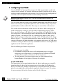
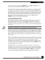
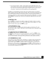
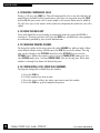
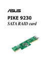
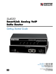
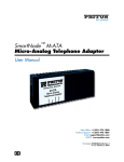
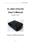
IP250D
VoIP Network Terminal
User’s Guide
For SIP and MGCP
Teledex LLC
6311 San Ignacio Avenue
San Jose, California 95119
USA
Contents Copyright © Teledex 2003. All Rights Reserved.
Telephone:
Fax:
Internet:
email:
(408) 363-3100
(408) 363-3136
www.teledex.com
[email protected]
Part Number 600-0480-60
SAFETY
IMPORTANT SAFETY INSTRUCTIONS
WHEN USING YOUR TELEPHONE EQUIPMENT, BASIC SAFETY PRECAUTIONS SHOULD ALWAYS BE FOLLOWED TO REDUCE
THE RISK OF FIRE, ELECTRIC SHOCK AND INJURY TO PERSONS, INCLUDING THE FOLLOWING:
1. READ AND UNDERSTAND ALL INSTRUCTIONS.
2. FOLLOW ALL WARNINGS AND INSTRUCTIONS MARKED ON THE PRODUCT.
3. UNPLUG THE PRODUCT FROM THE WALL OUTLET BEFORE CLEANING. DO NOT USE LIQUID CLEANER OR AEROSOL
CLEANERS. USE A DAMP CLOTH FOR CLEANING.
4. DO NOT USE THIS PRODUCT NEAR WATER; FOR EXAMPLE NEAR A BATHTUB, WASH BOWL, KITCHEN SINK OR
LAUNDRY TUB, IN A WET BASEMENT, OR NEAR A SWIMMING POOL.
5. DO NOT PLACE THIS PRODUCT ON AN UNSTABLE CART, STAND OR TABLE. THE PRODUCT MAY FALL, CAUSING
SERIOUS DAMAGE TO THE PRODUCT.
6. SLOTS AND OPENINGS IN THE CABINET AND THE BOTTOM ARE PROVIDED FOR VENTILATION, TO PROTECT
IT FROM OVERHEATING. THESE OPENINGS MUST NOT BE BLOCKED OR COVERED. THE OPENINGS SHOULD NEVER
BE BLOCKED BY PLACING THE PRODUCT ON A BED, SOFA, RUG OR ANY OTHER SIMILAR SURFACE. THIS PRODUCT
SHOULD NEVER BE PLACED NEAR OR OVER A RADIATOR OR HEAT REGISTER. THIS PRODUCT SHOULD NOT BE
PLACED IN A BUILT-IN INSTALLATION UNLESS PROPER VENTILATION IS PROVIDED.
7. NEVER PUSH OBJECTS OF ANY KIND INTO THIS PRODUCT THROUGH CABINET SLOTS AS THEY MAY TOUCH
DANGEROUS VOLTAGE POINTS OR SHORT OUT PARTS THAT COULD RESULT IN A RISK OF FIRE OR ELECTRIC
SHOCK. NEVER SPILL LIQUID OF ANY KIND ON THE PRODUCT.
8. TO REDUCE THE RISK OF ELECTRIC SHOCK, DO NOT DISASSEMBLE THIS PRODUCT, BUT TAKE IT TO QUALIFIED
SERVICE PERSONNEL WHEN SOME SERVICE OR REPAIR WORK IS REQUIRED. OPENING OR REMOVING COVERS
MAY EXPOSE YOU TO DANGEROUS VOLTAGES OR OTHER RISKS. INCORRECT REASSEMBLY CAN CAUSE ELECTRIC
SHOCK WHEN THE APPLIANCE IS SUBSEQUENTLY USED.
9. UNPLUG THIS PRODUCT FROM THE WALL OUTLET AND REFER SERVICING TO QUALIFIED SERVICE PERSONNEL
UNDER THE FOLLOWING CONDITIONS:
• WHEN THE POWER SUPPLY CORD OR PLUG IS DAMAGED OR FRAYED.
• IF LIQUID HAS BEEN SPILLED INTO THE PRODUCT.
• IF THE PRODUCT HAS BEEN EXPOSED TO RAIN OR WATER.
• IF THE PRODUCT DOES NOT OPERATE NORMALLY BY FOLLOWING THE OPERATING INSTRUCTIONS. ADJUST
ONLY THOSE CONTROLS THAT ARE COVERED BY THE OPERATING INSTRUCTIONS, AS IMPROPER ADJUSTMENT
OF OTHER CONTROLS MAY RESULT IN DAMAGE AND WILL OFTEN REQUIRE EXTENSIVE WORK BY A
QUALIFIED TECHNICIAN TO RESTORE THE PRODUCT TO NORMAL OPERATION.
• IF THE PRODUCT HAS BEEN DROPPED OR THE CABINET HAS BEEN DAMAGED.
• IF THE PRODUCT EXHIBITS A DISTINCT CHANGE IN PERFORMANCE.
10. AVOID USING A TELEPHONE (OTHER THAN A CORDLESS TYPE) DURING AN ELECTRICAL STORM. THERE MAY BE A
RISK OF ELECTRIC SHOCK FROM LIGHTNING.
ii
Teledex IP250D User’s Guide SIP/MGCP
Part Number 600-0480-60
NOTICES
REQUIREMENTS OF PART 15 - FCC RULES
NOTE: This equipment has been tested and found to comply with the limits for a Class A
digital device, pursuant to Part 15 of the FCC Rules. These limits are designed to provide
reasonable protection against harmful interference in a residential installation. This
equipment generates, uses, and can radiate radio frequency energy and, if not installed
and used in accordance with the instructions, may cause harmful interference to radio
communications. However, there is no guarantee that interference will not occur in a
particular installation. If this equipment does cause harmful interference to radio or television
reception, which can be determined by turning the equipment off and on, the user is encouraged to try to correct the interference by one or more of the following measures: a) move the
telephone away from the receiver; b) consult the dealer or an experienced radio/TV technician
for help. Any changes made by the user not approved by the manufacturer can void the user's
authority to operate the telephone.
EUROPEAN REQUIREMENTS
This product complies with the following CE requirements:
89/336/EEC
EN 55022
EN 55024
EN 60950 (CB SCHEME)
Teledex IP250D User’s Guide SIP/MGCP
iii
TABLE OF CONTENTS
Contents
1 Introduction to the IP250D VoIP Network Terminal 1
1.1 THE IP250D WORKS LIKE A TELEPHONE 1
1.2 TWO LINES 2
1.3 THE NETWORK 2
1.4 THE CALL CONTROL SERVER 2
1.5 THE NETWORK OR SYSTEM ADMINISTRATOR 2
2 Installing the IP250D 2
2.1 A MATTER OF SAFETY 2
2.2 UNPACKING THE IP250D 3
2.3 CONNECTING THE HANDSET 3
2.4 CONNECTING THE IP250D TO THE NETWORK 3
2.5 CONNECTING A PC TO THE IP250D 3
2.6 ARRANGING THE IP250D ON THE DESK 4
2.7 MOUNTING THE IP250D ON A WALL 4
2.8 CONNECTING A HEADSET TO THE IP250D 4
3 Configuring the IP250D 5
3.1 THE HOME PAGE 5
3.2 LAN CONFIGURATION 6
3.2.1 LAN INTERFACE SETTINGS 6
3.2.2 VLAN SETTINGS 6
3.3 MGCP CONFIGURATION 6
3.3.1 MGCP SETTINGS 7
3.3.2 OOB SIGNALLING SETTINGS 7
3.3.3 HANDSET SETTINGS 8
3.3.4 VLAN SETTINGS 8
3.4 SIP CONFIGURATION 8
3.4.1 SIP SETTINGS 8
3.4.2 OOB SIGNALLING SETTINGS 8
3.4.3 VLAN SETTINGS 9
3.5 CODEC CONFIGURATION 9
3.6 SYSTEM CONFIGURATION 9
3.6.1 SECURITY SETTINGS 9
3.6.2 LOCALIZATION SETTINGS 9
3.6.3 SNMP SETTINGS 10
3.7 DOWNLOAD CONFIGURATION 10
3.8 RESET CONFIGURATION 10
iv
Teledex IP250D User’s Guide SIP/MGCP
Part Number 600-0480-60
TABLE OF CONTENTS
4 Using the IP250D 11
4.1 TELEPHONE IDLE 11
4.2 INCOMING CALL NOTIFICATION 11
4.3 RECEIVING A CALL 11
4.4 PLACING A CALL 12
4.5 DTMF SIGNALLING 13
4.6 TERMINATING A CALL 13
4.7 HEADSET AND SPEAKERPHONE USAGE 13
4.8 HOLD AND MULTIPLE LINES 14
4.9 MUTING A CALL 16
4.10 TRANSFERRING A CALL 16
4.11 REDIALING THE LAST NUMBER DIALED 16
4.12 FORWARDING ALL CALLS 16
4.13 MAKING CONFERENCE CALLS 17
4.14 USING THE MSGS KEY 17
4.15 CHANGING RINGING SOUNDS 17
4.16 CONFIGURING LOCAL SPEED DIAL NUMBERS 17
5 Troubleshooting and Care 18
5.1 BASIC TROUBLESHOOTING MEASURES 18
5.2 GENERAL TROUBLESHOOTING 18
5.3 NETWORK TROUBLESHOOTING 18
5.4 MGCP-SPECIFIC ISSUES 20
5.5 SIP-SPECIFIC ISSUES 20
5.6 CLEANING THE IP250D 21
6 The Downloader Application 21
6.1 EXECUTING THE DOWNLOADER APPLICATION 21
6.2 USING THE DOWNLOADER APPLICATION 21
7 Appendix A: Determining the IP Address 22
8 Appendix B: Safe Bootup Modes 22
9 Appendix C: Restoring Factory Defaults 23
10 Appendix D: Dial Plans 24
11 Appendix E: Tone and Ring Cadence Configuration 25
12 Appendix F: IP250D Product Specifications 28
13 Appendix G: Product Support 29
Teledex IP250D User’s Guide SIP/MGCP
v
INTRODUCTION TO THE IP250D
1 Introduction to the Teledex IP250D VoIP Network Terminal
The Teledex IP250D VoIP network terminal is very similar to a modern business desk
telephone. Instead of using telephone lines, it connects to the office network in the same
manner as computers and printers do. The acronym VoIP means Voice over Internet
Protocol. The voice and control signals to and from the IP250D are entirely digital data
that is transmitted over the office data network, rather than phone lines.
FIGURE 1.1 – THE IP250D KEYSET
1.1 THE IP250D WORKS LIKE A TELEPHONE
The IP250D functions in a manner very similar to a modern office telephone that is
connected to a PABX (private automatic branch exchange.) In this user’s guide, the
IP250D VoIP network terminal will sometimes be referred to as a “phone.”
1
Teledex IP250D User’s Guide SIP/MGCP
Part Number 600-0480-60
INSTALLING THE IP250D
1.2 TWO LINES
The IP250D can handle one or two calls simultaneously, much like a standard “two-line”
analog or digital telephone. However, there is only one line (or cable) connecting the
IP250D to the network.
1.3 THE NETWORK
Instead of telephone lines, the IP250D connects to other IP phones via an Ethernet network.
1.4 THE CALL CONTROL SERVER
A specialized network server, called a “SIP server” for SIP IP phones, or a “Call Agent”
for MGCP phones, controls all of the IP250D terminals, and other types of VoIP
terminals that are connected to the network.
1.5 THE NETWORK OR SYSTEM ADMINISTRATOR
The IP250D requires configuration in order to work properly on the network. This task
is performed by a technical specialist referred to as a network or system administrator.
The network administrator will perform the configuration steps from a control station.
2 Installing the IP250D
Installing the IP250D at an office desk or workstation is as simple as installing a
conventional office telephone.
2.1 A MATTER OF SAFETY
!
WARNING
WARNINGS mean danger to persons and possibly, damage to equipment. Whenever you
see this symbol, be careful to study the steps that you will perform, and be sure that you
understand the nature of the hazards before beginning the task.
CAUTIONS mean risk of damage to equipment. Whenever you see this symbol, be aware
of the steps that you will perform and be sure that you avoid the conditions that may
damage the equipment.
NOTES point out exceptions or additions to the information presented in a particular
section. You may want to highlight some information that you will need to remember
periodically in the operation or installation of this device.
Teledex IP250D User’s Guide SIP/MGCP
2
INSTALLING THE IP250D
2.2 UNPACKING THE IP250D
The IP250D VoIP network terminal package contains several components:
• The main base unit, sometimes referred to as the keyset
• A handset for use during conversations
• A desk/wall mount bracket, to support the keyset at a convenient angle on
the desk, or for mounting the phone on a vertical surface, such as a wall
• A network patch cable for connecting the keyset to the network
• A handset coil cord, to connect the handset to the keyset
• Package may also contain an optional power supply (if necessary)
2.3 CONNECTING THE HANDSET
Plug one end of the coil cord into the RJ-10 receptacle on the handset and the other end
into the receptacle on the left front side of the keyset. Place the handset into the cradle of
the keyset.
2.4 CONNECTING THE IP250D TO THE NETWORK
!
WARNING
Warning! Risk of electrical shock! Dangerous voltages may be present on the terminals of
the network patch cable after it is plugged into the network wall jack. Connect the patch
cable to the keyset base first, then to the network wall jack.
Plug one end of the network patch cable into the RJ-45 receptacle labeled 10/100 SW on
the bottom of the IP250D keyset. Connect the other end of the cable to the network wall
jack (receptacle) designated by the network administrator.
Caution: Do not connect a telephone cord to the network RJ-45 jack. A standard RJ-11
telephone cord connector can fit into the RJ-45 jack, however there is risk of damaging the
equipment if this is done.
Note: The IP250D will not function until it has been configured and activated by the
network administrator.
2.5 CONNECTING A PC TO THE IP250D
If the office or cubicle space has only one active network receptacle, and another network
device such as a PC must share the same space, the PC should be disconnected from
the wall jack and reconnected to the RJ-45 receptacle on the bottom of the IP250D that
is labeled 10/100 PC.
3
Teledex IP250D User’s Guide SIP/MGCP
Part Number 600-0480-60
INSTALLING THE IP250D
Caution: The cable from the network wall jack must be connected to the connector marked
SW, and if there is a PC, it must be connected to the connector marked PC, otherwise the
IP250D will not function.
2.6 ARRANGING THE IP250D ON THE DESK
Route the network cable toward the rear of the keyset and attach the desk/wall
mounting bracket by inserting the snap fasteners into the matching holes in the base.
Place the unit at a convenient location on the desk. Be sure to replace the handset on the
cradle and ensure that the hookswitch is properly depressed by the weight of the earpiece
of the handset.
2.7 MOUNTING THE IP250D ON A WALL
The IP250D can be mounted on a wall or other vertical surface. To do so, the desk/wall
mounting bracket should be rotated 180 degrees, compared to the desk mounting
position. Use screws (and anchors, if necessary) to match the hole pattern in the bracket.
The wall mounting clip near the hookswitch should be removed and re-installed after
rotating it 180 degrees. To remove the clip, push it firmly toward the hookswitch.
The clip will hold the handset in the cradle and cause it to depress the hookswitch when
the phone is not in use.
2.8 CONNECTING A HEADSET TO THE IP250D
Two types of headsets may be connected to the IP250D:
a) The type that replaces the handset and connects to the RJ-10 handset cord receptacle
b) The type that connects to a 2.5 mm diameter jack (located on the right front side
of the keyset)
When using the 2.5 mm type, the handset should be left in the cradle, such that it
depresses the hookswitch. Please follow the headset manufacturer’s instructions when
using the type that replaces the handset.
Note: The handset, headset and speakerphone devices have special rules that describe their
modes of use, as described in section 4.7.
Teledex IP250D User’s Guide SIP/MGCP
4
CONFIGURING THE IP250D
3 Configuring the IP250D
Once the IP250D has been unpacked, set up on the desk (or mounted to a wall), and
connected to the network, the network administrator should be notified that the unit is
ready for network configuration and activation. Once the unit has been configured and
activated, it will receive power from the network and begin to function.
Note: The IP250D will not function until it has been configured and activated by the
network administrator.
The user cannot make any changes to the network configuration of the IP250D, but can
make certain changes to suit personal preferences, such as volume settings, ringer tones,
speed-dial phone numbers and the like. These steps are covered later in this manual.
This section contains information on how to access the device’s built in web pages for
further configuration. In order to access the built-in configuration web pages of the
device, you need to know its IP address. If you do not know the IP address of the unit,
refer to Appendix A for instructions on how to determine the unit’s IP address. If the IP
address is known, a web browser URL can be pointed to the address. Doing so will
display the device’s main configuration web page, which will look similar to that shown
below in Figure 3-1. The main configuration menu appears on the left of the screen. The
contents of this menu will differ depending on the purpose of the device, the VoIP protocol which is running on the device (if any), and whether the device is executing the main
application or the downloader application.
Note the following web browser requirements:
• Javacript must be enabled.
• For optimum viewing of the device's web configuration pages, we suggest
configuring your system display to a minimum viewing resolution of 800x600
and your browser display maximized to fill the viewing area.
• To avoid potential javascript execution errors, we also recommend using
Internet Explorer 4.0 or higher, or Netscape 4.0 or higher.
3.1 THE HOME PAGE
The home page is the first page displayed when the device’s web pages are accessed. It
shows how long the device has been running since its last reboot, the IP address the
device is currently using, whether or not the device is password protected, and also displays the main application and downloader application firmware versions. To navigate
the system settings, click on the selections to the left side of the page.
5
Teledex IP250D User’s Guide SIP/MGCP
Part Number 600-0480-60
CONFIGURING THE IP250D
FIGURE 3.1 – THE CONFIGURATION HOME PAGE
3.2 LAN CONFIGURATION
The LAN Configuration page allows configuration of the device’s local network settings.
Sub-pages are available to configure the LAN Interface settings.
3.2.1 LAN Interface Settings
This sub-page allows the user to configure the device’s LAN interface settings. Select
whether you wish for the device to be configured via a DHCP server on the network, or
statically configured. If you wish to statically assign the network settings, enter the IP
address, subnet mask, default gateway IP address and DNS server IP address. It is also
recommended that the network domain name be provided as well, to ensure correct DNS
operation. Press SAVE LAN SETTINGS to save the network settings.
3.2.2 VLAN Settings
To enable VLAN for network traffic, set the VLAN TAG AND PRIORITY TAG. Press SAVE
VLAN Settings to save the VLAN settings. Reset the unit to have the new settings take
effect.
3.3 MGCP CONFIGURATION
If the device is running the MGCP protocol, select MGCP from the menu. This will
provide sub-options to configure the MGCP server and device endpoint settings, how the
device is to handle any out-of-band (OOB) DTMF signaling, and VLAN prioritization
for MGCP packets.
Teledex IP250D User’s Guide SIP/MGCP
6
CONFIGURING THE IP250D
3.3.1 MGCP Settings
This sub-page allows configuration of the MGCP server and device endpoint settings.
Enter the address and port number of the MGCP Call Agent. The address may be an IP
address or the name of the server.
If no Call Agent address is entered, the device will attempt to self-provision a Call Agent
using a DNS query. For this to be successful, ensure that the DNS settings on the device
include a DNS server address which is configured with the Call Agent address, and will
respond to the query, and the appropriate domain name of the network.
For the endpoint, configure the domain name of the device as it will appear in all MGCP
signaling transactions with the call agent. For example, if the domain name is set to
"teledex.com", configure the domain name to read: aaln/[email protected]
If the domain name is left blank, the device’s IP address will be used as the domain name.
For example: aaln/1@[192.168.1.100]
Enter the maximum delay before the device will send out the RSIP message after it
powers up. The actual RSIP time-out will be a random number between zero and the
number entered on this page. If you wish for the device to immediately send the RSIP
after powering up, enter the value zero.
Under the compatibility section, select which MGCP "Profile" is to be used. Finally,
select whether the MGCP stack should employ message "piggybacking" whenever
possible when sending packets. Some older call agents do not support piggybacked
messages. Press SAVE MGCP SETTINGS to save the new values. Reset the unit to have the
new settings take effect.
3.3.2 OOB Signalling Settings
This sub-page configures the handling of out-of-band telephony events signalling using
the RFC2833 protocol over RTP. First, select whether telephony events are to be sent
using RFC2833, and the destination port value which should be used for the signalling.
Select whether any voice packets are to suppressed (dropped) during the transmission of
RTP RFC2833 signalling packets. Some networks may enforce this to ensure that no
extra bandwidth is consumed by the signalling. Select whether the inband audio DTMF
is to be "squelched" (i.e. the device on the other end will not hear any audio DTMF).
Select the ABCD event transition handling mode to be used. In transition mode,
signalling packets are only sent when the ABCD event changes state. In continuous mode,
ABCD packets are continuously sent for a particular ABCD state. Press SAVE RFC2833
SETTINGS to save the new values.
7
Teledex IP250D User’s Guide SIP/MGCP
Part Number 600-0480-60
CONFIGURING THE IP250D
3.3.3 Handset Settings
This sub-page allows configuration of the MGCP IP Phone display and function key
settings. If you want the IP phone’s extension number to be displayed on the LCD during
idle operation, enter the phone’s extension number, or leave blank if you wish not to
display a number. Enter the key / command sequences to be sent to the MGCP call agent
for class 5 features. The class 5 features available on the MGCP IP Phone are:
• Call Forwarding (FWD)
• Call Transfer (XFER)
• Call Hold / Retrieve (HOLD)
• Conference Calls (CONF)
If the key / command sequence contains a "flash" event, you may specify this by using
"f" or "F" (e.g. "F7" = "flash" + "7"). You may also enter the extension / number of the
voice mail (MSGs) service on the network. Press SAVE HANDSET SETTINGS to save.
3.3.4 VLAN Settings
To enable VLAN for MGCP and audio traffic, set the VLAN TAG and PRIORITY TAG. Press
SAVE VOIP VLAN SETTINGS to save the VLAN settings. Reset the unit to have the new
settings take effect.
3.4 SIP CONFIGURATION
If the device is running the SIP protocol, select SIP from the menu. This will provide sub
options to configure the SIP server and device endpoint settings.
3.4.1 SIP Settings
This page allows configuration of the SIP server and endpoint settings. Enter the IP
address and port value of the SIP server. If no SIP server address is entered, the device will
attempt to self-provision a SIP server using a DNS query. For this to be successful, ensure
that the DNS settings on the device include a DNS server address which is configured
with the SIP server address and will respond to the query, and the appropriate domain
name of the network. Enter the domain name of the network. For the endpoint, set the
dial plan to be used by all lines, and select the transport method to be used in the SIP
signalling (either UDP or TCP). For each line on the endpoint (note: the IP phone has a
single line), enter the line phone number, Caller ID name, signalling port value, password,
and select whether AEC is to be performed. All settings, except for the port value, are
optional. Press SAVE SIP SETTINGS to save the new values. Reset the unit to have the new
settings take effect.
3.4.2 OOB Signalling Settings
Under this section various options for handling DTMF are available. Press SAVE RFC2833
SETTINGS to save the new values. Reset the unit to have the new settings take effect.
Teledex IP250D User’s Guide SIP/MGCP
8
CONFIGURING THE IP250D
3.4.3 VLAN Settings
To enable VLAN for SIP and audio traffic, set the VLAN TAG and PRIORITY TAG. Press
SAVE VOIP VLAN SETTINGS to save the VLAN settings. Reset the unit to have the new
settings take effect.
3.5 CODEC CONFIGURATION
This page is available for configuring the audio CODEC parameters. Enter which codecs
are to be supported. For some protocols (e.g. SIP), the G711U and G711A protocols are
always supported by default. For MGCP, it is possible to remove these codecs from the
device’s list of supported "capabilities".
Select the appropriate complex codec if it is desired. Select the packetization period to be
used. For MGCP, a range of packetizations may be provided for each codec (to be
advertised in the device’s "capabilities" set.)
Finally, select whether silence suppression is to be supported for each codec. Press SAVE
CODEC SETTINGS to save the new codec parameters. These settings will only take effect
when the device is rebooted.
3.6 SYSTEM CONFIGURATION
This main menu option provides subpages to configure the device’s security and
localization settings.
3.6.1 Security Settings
This sub-page allows an administrator to configure the device with an access password.
Enter the password and confirm by reentering it. Press SAVE SECURITY SETTINGS to apply
the password protection. Effective immediately, the password will be required whenever
anyone wishes to access the device’s configuration web pages.
3.6.2 Localization Settings
This sub-page only applies to devices running a VoIP protocol, and is used to configure
the localization settings of the device. Enter the country (certain media hub devices
require this information in order to communicate with analog phones which follow different international standards.) If you wish for the device to automatically obtain the
time via NTP, enter the NTP server address for the network (if this address is left blank, a
default public NTP server will be used, if accessible). Select the time zone, and whether or
not to adjust for daylight savings. Press SAVE LOCALIZATION SETTINGS to save the new
values. These settings will only take effect when the device is rebooted.
9
Teledex IP250D User’s Guide SIP/MGCP
Part Number 600-0480-60
CONFIGURING THE IP250D
3.6.3 SNMP Settings
This sub-page is used for configuring the device’s SNMP server. Configure the SNMP
Trap Host IP address and community, the SNMP read and write community parameters,
and the SNMP System Description and System Object ID parameters. Press Save SNMP
Settings to apply the new values. These settings will only take effect when the device is
rebooted.
3.7 DOWNLOAD CONFIGURATION
This page provides two options for downloading a new firmware application image
to the device. If you wish to download the new firmware image using TFTP, enter the
filename of the ROM image and enter the IP address of the TFTP server on which this
file resides. Press START TFTP DOWNLOAD to initiate the TFTP download process.
If the ROM image is stored on the same local machine you are using to access the
device’s web pages, you can choose to download the ROM file to the device using an
HTTP post. Enter the filename of the ROM image or press BROWSE to help locate the
file. Press START HTTP DOWNLOAD to initiate the HTTP download process. If the main
application is executing at the time, the device will automatically reboot itself into the
downloader mode and begin the download process. If the downloader application is
executing at the time, the download process will begin. The download status will be
displayed when the image download process is complete. Please refer to Section 6, The
Downloader Application for more details on the download process.
3.8 RESET CONFIGURATION
This page provides options for resetting the device. Select whether you wish to reset the
device and start executing the main (default) application, or whether you wish to reset
the device and start executing the internal downloader application. Press RESET to reset
the device.
Teledex IP250D User’s Guide SIP/MGCP
10
USING THE IP250D
4 Using the IP250D
This section describes how to use the IP250D. The references and actions associated to
the "LINE 1", "LINE 2" keys and LEDs apply to the SIP version of the IP250D only.
The "LINE 1" and "LINE 2" keys and LEDs are inactive on the MGCP version.
4.1 TELEPHONE IDLE
The IP250D is in an idle state when the handset is on-hook, the headset and speaker are
off, and the user is not attempting to use or configure the phone in any way. The IP250D
displays the date and time when the telephone is in an idle state. The date and time may
be displayed in a MM-DD-YY, MM-DD, DD-MM-YY, or DD-MM format for the date
and a 24-hour or 12-hour format for the time. The phone also displays its extension
number or telephone number.
4.2 INCOMING CALL NOTIFICATION
The phone provides notification of an incoming telephone call in three ways:
1) The phone rings using a tone chosen by the user. Different ring tones may be
chosen for internal and external calls.
2) During an incoming call, the IP250D flashes the LED for line 1, if no lines are
active. If line 1 is active but line 2 is not, the phone flashes the LED for line 2,
and if line 2 is active but Line 1 is not, the phone flashes the LED for line 1.
3) The IP250D displays any caller information (if available) on its display.
4.3 RECEIVING A CALL
The IP250D allows the user to receive a call and establish a virtual audio connection with
the other party through the handset, speakerphone, or headset:
HANDSET – From the idle state, the user may receive a call by lifting the handset, thereby
placing the IP250D off-hook. If the user is already conducting a conversation with
another party, the call may be answered using the handset by placing the initial party on
hold and pressing the LINE 1 or LINE 2 key corresponding to the new call. If the phone is
idle but the handset is already off-hook when a call arrives, the user can receive the call
by hanging up the handset and lifting it again, or by pressing the LINE 1 or LINE 2 key
corresponding to the new call. The user will be able to identify the proper line key to
press because the LED above that key will be flashing.
11
Teledex IP250D User’s Guide SIP/MGCP
Part Number 600-0480-60
USING THE IP250D
HEADSET – For a SIP version phone only, the user may receive a call using the headset by
pressing the LINE 1 or LINE 2 key corresponding to the new call when a headset is plugged
in and the handset is down. The IP phone hardware accommodates two types of headsets,
and the software routes the virtual audio connection to both headset jacks whenever at
least one headset is plugged in. The software also routes the audio to the headset when
the handset is down.
SPEAKERPHONE – The user may receive a call on the speakerphone by pressing the
SPKR/HSET key or by pressing the LINE 1 or LINE 2 key corresponding to the new call if
the headset is not plugged in and the handset is on-hook. Once the call is received, the
caller information disappears, the flashing of the LED and ringing stops, and a virtual
audio channel for conversation is opened.
4.4 PLACING A CALL
The IP250D allows the user to initiate a call through the handset, speakerphone, or
headset as follows:
HANDSET – From the idle state, the user may initiate a call by lifting the handset and
placing the phone off-hook. The user should then listen for a dial tone and dial the
number or extension of the call recipient. The user may also initiate a call while already
on the line with another party.
HEADSET – The user may initiate a call from the idle state using the headset, by plugging
the headset in, keeping the handset on-hook, and pressing the SPKR/HSET key or pressing
the LINE 1 or LINE 2 key.
SPEAKERPHONE – The user may initiate a call on the speakerphone when the handset is
down and the headset is unplugged by pressing the SPKR/HSET key or pressing the LINE 1
or LINE 2 key.
When initiating a call, the LED corresponding to the appropriate line is lit continuously
and the number dialed is shown on the display. Once the user has finished dialing and a
virtual audio connection with the other party has been established, the display changes to
show the elapsed call time. All of the digits dialed while initiating the call are erased from
the display. The user may also dial using speed dial and directory features. During a
telephone conversation, The phone displays the time elapsed for the active call until the
conversation is terminated. The time is displayed in HH:MM:SS format. In the unlikely
event that a call lasts for 100 hours or more, the display simply rolls over to start at 0,
instead of consuming an extra character on the display. The LED for the appropriate line
is lit continuously.
Teledex IP250D User’s Guide SIP/MGCP
12
USING THE IP250D
The volume of the handset can be increased or decreased by pressing the up or down
volume keys. The volume buttons adjust the volume for the currently active call. The
volume settings may be saved for future calls by setting the volume to the desired level
and pressing the PROGRAM key immediately afterward.
4.5 DTMF SIGNALING
Virtually all telephony applications, such as those used by customer service centers and
calling cards, require touch tone data entry. For example, calling cards frequently request
that the user press ‘1’ for English and ‘2’ for Spanish. The technical name for the tones
generated by pressing digits on the keypad is dual tone multiple frequency, or DTMF.
The IP250D supports DTMF signaling by generating DTMF tones over the virtual audio
connection. The keys pressed during telephone calls are also displayed on the display
below the call duration indicator. The digits begin appearing on the second row (left side)
of the display. Each line on the display has room for sixteen digits; the display scrolls to
the left when the user dials a number exceeding sisxteen digits in length, and will
continue to scroll as more numbers are dialed.
4.6 TERMINATING A CALL
You may terminate a call by various methods, depending upon whether you are using the
handset, speakerphone or a headset:
• If using the handset, the call may terminated by replacing the handset on
the cradle.
• If using a headset, the call may be terminated by pressing the SPKR/ HSET key, or
by lifting the handset off the cradle and then putting it down again on the cradle.
• If using the speakerphone, the call may be terminated by pressing the SPKR/HSET
key, or by picking up the handset off the cradle and putting it down again.
If no other call is active, the phone will revert to the idle state upon the termination of a
conversation. If another call is active, and therefore on hold, it will remain on hold until
the user takes it off hold, or the other party terminates the conversation. In either case,
the software will turn off the LED corresponding to the formerly active line.
4.7 HEADSET AND SPEAKERPHONE USAGE
The IP250D software routes the voice to the handset, speakerphone, or headset based
upon the actions of the user. The software gives the highest priority to the handset,
secondary priority to the headset, and lowest priority to the speakerphone. If a call is
initiated while the handset is off-hook, or if a call is received and the user takes the
handset off hook, the audio channel will be routed through the handset. The headset
may be activated by pressing the SPKR/HSET key while on the handset, and then putting
13
Teledex IP250D User’s Guide SIP/MGCP
Part Number 600-0480-60
USING THE IP250D
the handset down, or by pressing the SPKR/HSET key, or the LINE 1 or LINE 2 keys to
initiate or receive the call while the handset is on hook.
The audio channel is routed to the speakerphone if the headset is not plugged in, and to
the headset jack if the headset is plugged in. To switch from headset to speakerphone,
unplug the headset from the headset jack. To switch from speakerphone to headset, plug
the headset back in. In order to switch from the speaker or headset back to the handset,
pick up the handset. The software will not allow more than one speaking device to be
used at a time. While the speakerphone or headset is active, the LED above the
SPKR/HSET button on the keypad will be illuminated.
4.8 HOLD AND MULTIPLE LINES
While engaged in conversation on a particular line, the HOLD feature may be used to
mute both the microphone and speaker on the handset, speakerphone, or headset
(depending on which is in use) by pressing the HOLD key. Placing a call on hold allows
the alternate line to be used to either receive or initiate a new call, without disconnecting
the first call.
Note: Placing a call on hold does not allow access to any functions, such as programming or
phone book, for example, that are not available in normal conversation mode.
In order to indicate that a call is on hold (SIP phone only) the software flashes the LED
above the button for the line on hold. The flashing pattern for HOLD is slow and continuous, as opposed to the flashing pattern for an incoming call notification, in which the
LED flashes quickly for two seconds with each ring and then turns off for several seconds
between rings.
When a call is on hold, the system continues to count the time elapsed for the call, even if
the user switches lines. For example, if the user speaks to another party for thirty seconds
and then places that party on hold for thirty more seconds, the display will read
"00:01:00" when the other party is taken off hold. The call will cease being on hold if
the other party hangs up, or if the user releases the hold by pressing the HOLD key, or the
key corresponding to the line on hold.
The IP250D (SIP version) allows for two virtual lines to be active at any time. The
functionality of the two lines is similar to the feature of call waiting on analog telephones,
except that you may use the line keys to switch between lines, instead of using the hook
switch. The virtual lines are accessed through the LINE 1 and LINE 2 keys; the status of
any line is displayed through the LED above the corresponding button as follows:
Teledex IP250D User’s Guide SIP/MGCP
14
USING THE IP250D
• When a line is inactive, the corresponding LED is off.
• When a line is ringing, the corresponding LED flashes quickly for two seconds
with each audible ring and turns off in between rings. This flashing pattern is used
even when the ring is not audible.
• When an user is initiating a call, or conducting a conversation on a particular line,
the corresponding LED is illuminated continuously.
• When a line is on hold, the corresponding LED flashes slowly.
The IP250D software gives notification of a second incoming call regardless of whether
the user is initiating a call, conducting a conversation, receiving another call, or on hold
on the first line. In the descriptions below of scenarios for the second incoming call, the
descriptions of line 1 and line 2 can be interchanged freely except where otherwise noted.
• If the user is initiating a call on line 1 when the second call arrives, the LED for
line 2 will also begin flashing, and the call information for the incoming call will
be shown on the display. The second call may be received by pressing on the
LINE 2 key, by hanging up the handset and picking it up again, or by pressing the
SPKR/HSET key once to hang up, and once again to pick up if using the speaker
phone or headset. To continue initiating the original call, simply continue dialing.
The display will change back to the dialing screen for each subsequent key
pressed.
• If the user is conducting a conversation on line 1 when a call arrives on line 2,
a half-second tone will sound on the receiver of the speaking device (handset,
speakerphone, or headset), the LED for line 2 will begin flashing, and the call
information for the incoming call is shown on the display. If the user begins
pressing keypad buttons for DTMF signaling, the display will change to the
DTMF signaling screen, then change back to the incoming call screen after six
seconds. To receive the second call, either press the LINE 2 key, which will auto
matically place the line 1 call on hold, or press HOLD and then the LINE 2 key.
Otherwise, the phone will produce a half-second tone on the receiver of the
speaking device every twelve seconds until the calling party on line 2 hangs up or
the incoming call is sent to the voicemail server. The incoming call may not be
forwarded directly to voicemail.
• If one call arrives, and then another call arrives before the user can receive the
first call, the ringer will ring as usual, but both the LEDs for lines 1 and 2 will
flash. In addition, the display will alternate every six seconds between the infor
mation for the call on line 1 and the information for the call on line 2. To answer
the call on line 2 first, press the LINE 2 key to place the call on speakerphone and
then pick up the handset if you so desire.
15
Teledex IP250D User’s Guide SIP/MGCP
Part Number 600-0480-60
USING THE IP250D
• If a call arrives on line 1 while a conversation is being conducted on line 2, the
conversation on line 2 may be terminated by hanging up the call. After the call on
line 2 has been terminated, the phone begins using the normal ring tone for the
call on line 1 rather than the half-second tone on the speaking device.
In addition to accommodating incoming calls on the second virtual line, the software
allows outgoing calls to be made on the second line. This can be done by placing the first
line on hold, and then dialing the destination number (using the keypad, speed dial, or
the directory.) Both lines may be placed on hold simultaneously. If both lines are on hold
and the HOLD key is pressed, the call that was first placed on hold will be the one that is
released.
4.9 MUTING A CALL
Press the MUTE key to mute the microphone of either the handset, headset, or speakerphone, depending on which is in use. A green LED indicates that the phone is in "mute"
mode. To remove mute, repress the MUTE key again.
4.10 TRANSFERRING A CALL
To transfer a call, press the XFER key, then dial the number to which the call is to be
transfered When either a ring or a dial tone is heard, the phone may be hung up to complete the transfer.
4.11 REDIALING THE LAST NUMBER DIALED
The REDIAL key allows the last ten numbers dialed to be viewed. Press REDIAL and use
the SCROLL keys to see the last ten numbers dialed. Press the keys 0-9 on the keypad to
select the desired number. (Pressing the ‘0’ key will dial the tenth number on the list.)
4.12 FORWARDING ALL CALLS
Your calls may be forwarded to either an IP phone or standard analog or digital phone,
including wireless phones. To do this, place the phone off hook in either handset or
headset mode. Press the FWD key. Dial the number to which calls are to be forward.
To deactivate call forwarding, go off hook and press the FWD key. While the phone is in
the call forward state, the message FORWARDING TO: and the number to which calls are
to be forwarded is displayed on the LCD.
Teledex IP250D User’s Guide SIP/MGCP
16
USING THE IP250D
4.13 MAKING CONFERENCE CALLS
During a call, press the CONF key. This will automatically select a new line and place the
original party on hold. Dial the second party; when they are connected, press the CONF
key to add this party to the call. As many people as the system allows may be added to
the call. Once you (as the initator of the conference) drop from the conference, the call is
ended.
4.14 USING THE MSGS KEY
Voice mail should be set up according to instructions from the system the IP250D is
running on. To connect to voice mail, press the MSGS key and follow the voice prompts
or instrcutions provided by your system administrator..
4.15 CHANGING RINGING SOUNDS
To change the volume of the ringer, press the either VOLUME key while on hook. Adjust
to the desired volume setting, and then press the PGM Key to set the volume. The ring
tone can be selected via the SETTINGS menu. Press the SETTINGS key to access the
SETTINGS menu. Follow the sequence: press 1 to enter PHONE SETUP mode; press 2 to
enter RINGER mode; press 1 to enter RINGER TONES, then set the ring tone. Select from
numbers 1 through 8 to choose the desired ring tone.
4.16 CONFIGURING LOCAL SPEED DIAL NUMBERS
To program configurable autodial keys for numbers:
1)
2)
3)
4)
17
Press the PGM key
Dial the number you want to store
Press the memory dialing key where you want to store the number
Press the PGM key again to complete the process.
Teledex IP250D User’s Guide SIP/MGCP
Part Number 600-0480-60
TROUBLESHOOTING AND CARE
5 Troubleshooting and Care
This section covers troubleshooting and caring for your IP250D.
5.1 BASIC TROUBLESHOOTING MEASURES
If the IP250D does not seem to function as expected, there are several troubleshooting
techniques that may be tried before contacting the network administrator.
5.1.1 Disconnect From the Network
Unplug the network patch cable from the wall jack. Wait at least fifteen (15) seconds,
then plug the cable back into the same jack. The IP250D will attempt to re-establish
contact with the SIP server or Call Agent. In many cases of malfunction, this should
restore normal operation.
!
WARNING
Warning: Risk of electrical shock! Dangerous voltages may be present on the exposed
terminals of the network patch cable after it is plugged into the network wall jack.
5.1.2 Disconnect the PC
If there is a PC or other network device connected to the “PC” network port, disconnect
the patch cable to the PC from the base of the keyset, then perform the actions from section 5.1.1, Disconnect From the Network.
5.1.3 Check the Cords and Cables
If the previous two steps do not solve the problem, all of the cords and cables (including
handset cord and headsets) should be disconnected, inspected for dirt or corrosion, and
reconnected.
5.2 GENERAL TROUBLESHOOTING
SYMPTOM: There is no LED or display activity at power on.
SOLUTION:
Check that the power supply unit (PSU) is properly connected.
5.3 NETWORK TROUBLESHOOTING
SYMPTOM: General network activity problems. The device does not appear to be
performing any network-related functions.
SOLUTION A: Ensure that the ethernet cable connection is secure, and that the link
indicators at both ends of the ethernet cable are active.
SOLUTION B: Try pinging the phone’s IP address from any Unix or Windows machine
connected to the same network. Type:
ping www.xxx.yyy.zzz [Enter]
(where www.xxx.yyy.zzz is the IP address of the unit).
Teledex IP250D User’s Guide SIP/MGCP
18
TROUBLESHOOTING AND CARE
SYMPTOM: The device’s Web pages are not accessible.
SOLUTION A: Ensure that the ethernet cable connection is secure, and that the link
indicators at both ends of the ethernet cable are active.
SOLUTION B: Try pinging the phone’s IP address from any Unix or Windows machine
connected to the same network. Type:
ping www.xxx.yyy.zzz [Enter]
(where www.xxx.yyy.zzz is the IP address of the unit).
SYMPTOM: The device does not respond to pings.
SOLUTION A: Ensure that the ethernet cable connection is secure, and that the link
indicators at both ends of the ethernet cable are active.
SOLUTION B: Verify that the DHCP server on the network is functioning.
SOLUTION C: If you do not have a DHCP server, or want to use a fixed IP address instead,
you need to reconfigure the device to use a static network assignment
(refer to section 3.2.1).
SYMPTOM: The LCD displays "Acquiring IP Address" indefinitely.
SOLUTION A: The unit is trying to acquire a DHCP IP address. Ensure that the ethernet
cable connection is secure, and that the link indicators at both ends of the
ethernet cable are active.
SOLUTION B: Verify that the DHCP server on the network is functioning.
SOLUTION C: If you do not have a DHCP server, or want to use a fixed IP address instead,
you need to reconfigure the device to use a static network assignment
(refer to section 3.2.1).
SYMPTOM: The automatic DNS discovery process for a VoIP server (MGCP call control
agent or SIP server) does not appear to work.
SOLUTION A: Ensure that the DNS server is capable of servicing DNS TXT or SRV
queries, and that it is configured to respond with the correct server
information when queried.
SOLUTION B: If the device is configured via DHCP, ensure that the DHCP server has
provided the correct DNS server and domain name information.
SOLUTION C: If the device network information has been statically assigned (i.e. not via
DHCP), ensure that the DNS server IP address is correct, and that the
network domain name has been provided and is correct.
SYMPTOM: The web browser complains often about errors on the page.
SOLUTION : Ensure that the web browser supports frames and that javascript is enabled.
Although the device’s internal web pages should be accessible from most
modern web browsers, Teledex recommends using Internet Explorer 4.0 or
higher, or Netscape 4.0 or higher for optimal results.
19
Teledex IP250D User’s Guide SIP/MGCP
Part Number 600-0480-60
TROUBLESHOOTING AND CARE
SYMPTOM: I’ve forgotten the IP address of the device, and hence cannot reach it via my
web browser.
SOLUTION : See Appendix A for instructions on how to determine the IP address of the
phone.
5.4 MGCP-SPECIFIC ISSUES
SYMPTOM: There is no dial tone when the phone is picked up.
SOLUTION A: There is no Call Agent configured. See section 3.2.1 on how to configure the
Call Agent.
SOLUTION B: The DNS discovery of a Call Agent has failed. Refer to section 5.2 on DNS
discovery troubleshooting.
SOLUTION C: The device is not getting a response from the Call Agent.
SOLUTION D: Check that the address and port of the Call Agent are configured correctly
for the device.
SOLUTION E: Ensure that the Call Agent is functioning correctly.
SOLUTION F: Check that the registration of the device in the Call Agent is correct.
Make sure that the Call Agent has registered the correct IP address of the
unit, and that any other endpoint-specific details (e.g. domain name,
codec preferences, etc. if applicable) are set correctly.
SOLUTION G: Ensure that the ethernet cable connection is secure, and that the link
indicators at both ends of the ethernet cable are active.
SOLUTION H: Check that the device is connected to the network (try accessing the device’s
web pages or pinging the device).
5.5 SIP-SPECIFIC ISSUES
SYMPTOM: There is no dial tone when the phone is picked up.
SOLUTION A: There is no SIP server configured. See section 3.2.1 for information on how
to configure the SIP server settings.
SOLUTION B: The DNS discovery of a SIP server has failed. Refer to section 5.2 on DNS
discovery troubleshooting.
SOLUTION C: Check that the IP address and port of the SIP server are configured correctly
for the device.
SOLUTION D: Ensure that the SIP server is functioning correctly.
SOLUTION E Ensure that the ethernet cable connection is secure, and that the link
indicators at both ends of the ethernet cable are active.
SOLUTION F: Check that the device is connected to the network (try accessing the device’s
web pages or pinging the device).
Teledex IP250D User’s Guide SIP/MGCP
20
THE DOWNLOADER APPLICATION
5.6 CLEANING THE IP250D
Dust or deposited materials caused by normal handling of the IP250D handset or keyset
should be removed occasionally to ensure optimal performance. Use a soft cloth moistened
with water to wipe the plastic exterior parts.
Caution: Do not use solvents, powders or spray cleansers that may leak into the electronic
components and cause damage.
6 The Downloader Application
This section describes how to execute the downloader application and use it to upgrade
the main application firmware ROM image.
6.1 EXECUTING THE DOWNLOADER APPLICATION
The downloader application may be executed in one of three ways:
1) Click the "Downloader" option on the main web page.
2) From the "Reset" option on the web page main menu. Select the option "Reset
and execute Downloader Application" and press the "Reset" button.
3) Force the device to execute the Downloader Application after power cycling.
Refer to Appendix B for details on how to force the downloader application to
execute using a ’safe’ mode.
6.2 USING THE DOWNLOADER APPLICATION
If the downloader application is running, use a web browser on the same logical network
as the device to access the device’s configuration web pages (see Section 3 “Configuring
the Platform"). From here, the device’s network and system settings may be reconfigured.
These pages provide two options for downloading a new firmware application image
to the device. If you wish to download the new firmware image using TFTP, enter the
filename of the ROM image, and enter the IP address of the TFTP server on which this
file resides. Press "Start TFTP Download" to initiate the TFTP download process.
If the ROM image is stored on the same local machine you are using to access the
device’s web pages, you can choose to download the ROM file to the device using an
HTTP post. Enter the filename of the ROM image, or press "Browse" to help locate the
file. Press "Start HTTP Download" to initiate the HTTP download process.
21
Teledex IP250D User’s Guide SIP/MGCP
Part Number 600-0480-60
APPENDICES
If the main application is executing at the time, the device will automatically reboot
itself into the downloader mode and begin the download process. If the downloader
application is executing at the time, the download process will begin. The download
status will be displayed when the image download process is complete. After the
download is completed, the download status page will be displayed. If the download
repeatedly fails, please contact your technical support representative.
A typical download takes about one minute, although it may take up to two minutes if
the network link is slow or congested.
!
WARNING
Warning: Once the download is in progress, it MUST be allowed to complete in its entirety, or
the main application image will be destroyed. If an irrecoverable error occurs, reboot the
device. It will automatically start in the downloader application and allow you to reattempt
a download of the new firmware image.
7 Appendix A: Determining the IP Address
This section provides instructions on how to determine the IP address of a unit. The
following general instructions can be followed to determine the IP address of a unit:
1)
2)
3)
4)
Press the SETTINGS button to access the unit’s settings configuration menu.
Press ‘2’ to select the NETWORK CFG menu.
Press ‘1’ to select the HOST CONFIG menu.
Press ‘1’ to view the host’s IP address.
8 Appendix B: Safe Bootup Modes
It is possible to boot the downloader application on the unit into a ‘safe’ mode. The
following safe modes exist:
FORCE DHCP MODE: This will force the unit to execute the downloader application
and attempt to obtain an IP address via DHCP.
2) FORCE FIXED IP MODE: This will force the unit to execute the downloader application
and use the fixed IP address configured in the unit. If no fixed IP has been configured
for the device, the unit will attempt to obtain an address via DHCP.
3) FORCE IP ADDRESS OF 10.1.0.54: This will force the unit to execute the downloader
application and use the IP address 10.1.0.54. A computer on the same logical
network (10.1.0.x) of the device (e.g. 10.1.0.39) can now access the device’s web
configuration pages. You can then proceed to reconfigure the network settings
(LAN option).
1)
Teledex IP250D User’s Guide SIP/MGCP
22
APPENDICES
Once the downloader application is running, the unit’s web page will display downloader
options only, and not application choices such as protocol (SIP or MGCP) and audio
codecs. In any of the above safe modes, VLAN will be disabled.
8.1 ’SAFE’ MODES ON AN IP PHONE
The IP Phone can be forced into a ‘safe’ downloader mode by doing the following:
1) Take the handset off-hook.
2) To restore the device's factory defaults (no call agent, boot using DHCP),
continue holding down the ‘1’ key for four (4) seconds during power up.
The IP250D’s LCD will display a countdown during the four second timeout.
After four seconds, the config file will be erased, and the unit will reboot the
main application.
3) To use 10.1.0.54, press the star (*) key during power up.
4) To use a previously-configured fixed IP address, press the ‘0’ key during power
up. If no fixed IP address was previously configured, the unit will use DHCP to
acquire an IP address.
5) To use DHCP, press the pound (#) key during power up.
9 Appendix C: Restoring Factory Defaults
This section describes how to restore the factory default settings of your IP250D.
Restoring the default settings is equivalent to clearing the internal ROM configuration
file. The IP250D can be restored to its default settings by doing the following:
1) Take the handset off hook.
2) Power cycle the device while holding down key ‘1’ for four (4) seconds. The
display will count down, indicating the time remaining until the factory defaults
will be restored. After four (4) seconds, the message DEFAULTS RESTORED will be
displayed on the LCD, and the phone will reboot.
The same result can be obtained by using the t2burn application and specifying an empty
configuration file. For example:
t2burn NONE NONE empty.cfg <platform>
23
(where empty.cfg is an empty config file).
Note: It is important that the ‘1’ key be held for four (4) seconds from the point at which
the unit reboots. Releasing the ‘1’ key before four seconds elapse will abort the restoration
and continue with the normal booting procedure.
Teledex IP250D User’s Guide SIP/MGCP
Part Number 600-0480-60
APPENDICES
10 Appendix D: Dial Plans
The IP Phone SIP code will allow provisioning (via web browser) of the dial plan. A dial
plan gives the unit a map to determine when a complete number has been entered and
should be passed to the gatekeeper for resolution into an IP address. Dial plans are
expressed using the same syntax as used by MGCP NCS specification. The formal syntax
of the dial plan is described by the following notation:
DIGIT ::= "0" | "1" | "2" | "3" | "4" | "5" | "6" | "7" | "8" | "9"
TIMER ::= "T" | "T"
LETTER ::= DIGIT | TIMER | "#" | "*" | "A" | "A" | "B" | "B" | "C" | "C"
| "D" | "D"
RANGE ::= "X" | "X" -- MATCHES ANY DIGIT
| "[" LETTERS "]" -- MATCHES ANY OF THE SPECIFIED LETTERS
LETTERS::= SUBRANGE | SUBRANGE LETTERS
SUBRANGE::= LETTER -- MATCHES THE SPECIFIED LETTER
| DIGIT "-" DIGIT -- MATCHES ANY DIGIT BETWEEN FIRST AND LAST
POSITION::= LETTER | RANGE
STRINGELEMENT::= POSITION -- MATCHES ANY OCCURRENCE OF THE POSITION
| POSITION "." -- MATCHES AN ARBITRARY NUMBER OF OCCURRENCES
INCLUDING 0
STRING ::= STRINGELEMENT | STRINGELEMENT STRING
STRINGLIST::= STRING | STRING "|" STRINGLIST
DIALPLAN::= STRING | "(" STRINGLIST ")"
A dial plan, according to this syntax, is defined either by a (case insensitive) string or by a
list of strings. Regardless of the above syntax, a timer is only allowed if it appears in the
last position in a string (12T3 is not valid). Each string is an alternate numbering scheme.
The unit will process the dial plan by comparing the current dial string against the dial
plan, if the result is under-qualified (partial matches at least one entry) then it will do
nothing further. If the result matches or is overqualified (no further digits could possibly
produce a match) then send the string to the gatekeeper and clear the dial string.
The timer T is activated when it is all that is required to produce a match. The period of
timer T is four (4) seconds. For example, a dial plan of (xxxT|xxxxx) will match
immediately if five (5) digits are entered, it will also match after a four (4) second pause
when three (3) digits are entered.
Teledex IP250D User’s Guide SIP/MGCP
24
APPENDICES
10.1 SAMPLE DIAL PLANS
Simple Dial Plan
Allows dialing of seven (7) digit numbers (e.g. 5551234) or an operator on 0.
Dial plan is (0T|xxxxxxx)
Non-Dialed Line Dial Plan
As soon as handset is lifted, the unit contacts the gatekeeper (used for systems where
DTMF detection is done in-call). Dial plan is (x.) i.e. match against 0 (or more) digits.
(Note: the dot ‘.’)
Complex Dial Plans
Local operator on 0, long distance operator on 00, four-digit local extension number
starting with 3, 4 OR 5, seven-digit local numbers prefixed by an 8, two-digit star services
(e.g. *69), ten-digit long distance prefixed by 91, and international numbers starting with
9011+ variable number of digits, are all examples of complex dial plans. The dial plan
rule for these is:
(0T|00T|[3-5]xxx|8xxxxxxx|*xx|91xxxxxxxxxx|9011x.T)
11 Appendix E: Tone and Ring Cadence Configuration
The various tone patterns generated by the IP Phone are all configurable via the standard
config variable process. In addition, the ring cadence patterns used are also configurable.
This section describes how to configure tones and ring cadence patterns.
11.1 TONE CONFIGURATION
The "language" for specifying the tone components is quite simple. They can be
summarized by the following BNF:
Freqval ::= frequency in Hertz
Powerval ::= power in Dbm0
Timeval ::= time in milliseconds
Repeatval ::= # of cycles to repeat
Tonename ::= "DTMF_0" | "DTMF_1" | "DTMF_2" | "DTMF_3" |
"DTMF_4" |"DTMF_5" | "DTMF_6" | "DTMF_7" | "DTMF_8" | "DTMF_9"
|"DTMF_STAR" | "DTMF_POUND" | "DTMF_A" | "DTMF_B" |"DTMF_C" |
"DTMF_D" |"DIALTONE" | "BUSY" | "RINGBACK" | "CALLWAITING" |
"NETWORK_BUSY" | "CONFIRM" | "STUTTER_DIAL" | "OFF_HOOK_WARN"
|"MSG_WAIT_INDICATOR" | "REORDER" | "CUSTOM_1" | "CUSTOM_2" |
25
Teledex IP250D User’s Guide SIP/MGCP
Part Number 600-0480-60
APPENDICES
"CUSTOM_3" | "CUSTOM_4" | "CUSTOM_5" | "CUSTOM_6" |
"CUSTOM_7" |"CUSTOM_8" | "CUSTOM_9"
Idle ::= "IDLE"
Active ::= "ON" | "OFF"
Inactive ::= Idle "(" Timeval ")"
Active ::= Active "(" Timeval ")"
Sequence ::= Active | Active "," Sequence
Repetition ::= "[" Sequence "]" Repeatval
Repeat ::= "R"
Cycle ::= Sequence | Repetition
Fullsequence ::= Cycle | Cycle "," Fullsequence
Cadence ::= Fullsequence | Fullsequence "," Repeat |
Fullsequence ","
Inactive "," Repeat
Toneref ::= "{" Tonename "}"
Toneseq ::= Toneref | Toneref "|" Toneseq
Freqcomp ::= Freqval "@" Powerval
Freq ::= Freqcomp | Freqcomp "+" Freqcomp
Tone ::= Toneseq | Freq "#" Cadence
EXAMPLE TONE CONFIGURATIONS
Example 1: A European Dial Tone
DIALTONE 425@-5#ON(1000),R
Example 2: A European Ringback Tone
RINGBACK 425@-10#ON(1000),OFF(5000),R
Example 3: Custom Tones
CUSTOM_1 950@-25#ON(330),OFF(30)
CUSTOM_2 1400@-25#ON(330),OFF(30)
CUSTOM_3 1800@-25#ON(330),OFF(30),IDLE(1000)
CUSTOM_4 {CUSTOM_1}|{CUSTOM_2}|{CUSTOM_3}
A Config File Example
Name Value
DIALTONE 450@-5#ON(1000),R
RINGBACK 450@-10#ON(1000),OFF(4000),R
NETWORK_BUSY 450@-10#ON(350),OFF(350),R
BUSY 450@-10#ON(350),OFF(350),R
Teledex IP250D User’s Guide SIP/MGCP
26
APPENDICES
11.2 RING CADENCE CONFIGURATION
Using the above notation, the BNF description for the ring cadence patterns is as follows:
Timeval ::= time in milliseconds
Repeatval ::= # of cycles to repeat
Tonename ::= "RING_0" | "RING_1" | "RING_2" | "RING_3" |
"RING_4"| "RING_5" | "RING_6" | "RING_7" | "RING_8" |
"RING_9"
Idle ::= "IDLE"
Active ::= "ON" | "OFF"
Inactive ::= Idle "(" Timeval ")"
Active ::= Active "(" Timeval ")"
Sequence ::= Active | Active "," Sequence
Repetition ::= "[" Sequence "]" Repeatval
Repeat ::= "R"
Cycle ::= Sequence | Repetition
Fullsequence ::= Cycle | Cycle "," Fullsequence
Cadence ::= Fullsequence | Fullsequence "," Repeat |
Fullsequence"," Inactive "," Repeat
Ring ::= Cadence
EXAMPLE RING CADENCE CONFIGURATION
200ms
100ms
300ms
400ms
200ms
200ms
4000ms
100ms
300ms
200ms
400ms
4000ms
1 cycle
For the ring cadence pattern above, the configuration would be:
RING_0 ON(200),OFF(300),ON(100),OFF(400),ON(200),OFF(4000),R
The Bellcore standard ring cadence patterns are:
NAME VALUE
RING_0 ON(2000),IDLE(4000),R
RING_1 ON(800),OFF(400),ON(800),IDLE(4000),R
27
Teledex IP250D User’s Guide SIP/MGCP
Part Number 600-0480-60
APPENDICES
RING_2 [ON(400),OFF(200)]2,ON(800),IDLE(4000),R
RING_3 ON(300),OFF(200),ON(1000),OFF(200),ON(300),IDLE(4000),R
RING_4 ON(500)
RING_5
RING_6
RING_7
RING_8
RING_9
200MS
00MS
200MS 100MS
400MS 4000MS
200MS
300MS
200MS 100MS
400MS 4000MS
CYCLE
12 Appendix F: IP250D Product Specifications
TELEPHONE TYPE
Two-line, VoIP (Voice over Internet Protocol) network terminal
CALL CONTROL PROTOCOLS
Compatible with SIP, MGCP protocols
DIALING KEYPAD
12 keys: numeric 1 – 9, 0, *, # capable of DTMF signaling (dual-tone multiple frequency)
SPEED (OR MEMORY) DIALING
10 keys, user-programmable
DISPLAY KEYS
Settings, Program, Directory, Contrast, Scroll Up / Down
LINE KEYS
Hold, Line 1, Line 2, Conference, Mute, Speaker / Headset
FUNCTION KEYS
Forward, Messages, Transfer, Redial, Volume Up / Down
Teledex IP250D User’s Guide SIP/MGCP
28
PRODUCT SPECIFICATIONS
DISPLAY
LCD, 3 lines x 16 characters, backlit
INDICATORS
LEDs: Message Waiting, Line 1, Line 2, Conference, Mute, Speaker / Headset
NETWORK CONNECTION
Ethernet 10/100BaseT, RJ-45 connector, 2 ports:
-Uplink to network and switch
-Pass-through, switched, for local PC
AUDIO INPUT / OUTPUT
Handset (included), RJ-10 connector
Headset (not included), 2.5 mm jack (or, RJ-10 handset replacement style may be used)
Microphone (built-in)
Speaker (built-in)
POWER
Power supplied from network switch
(wall-mounted AC adapter accessory available if network does not supply power)
SIZE
8.8” wide x 7.0” deep x 3.8” high
WEIGHT
2.2 pounds
13 Appendix G: Product Support
If you need technical assistance with this Teledex product, please contact us via one of
the following methods:
EMAIL
[email protected]
TELEPHONE
(408) 363-3100
INTERNET
www.teledex.com
If you feel that the information contained herein does not represent the way your
product is operating, check our website (www.teledex.com) for the latest version
of this documentation.
29
Teledex IP250D User’s Guide SIP/MGCP
Part Number 600-0480-60