1
SpeedTouch™
605/608/608 WL/620
(Wireless) Business DSL Routers
User’s Guide
Release R5.3.1
SpeedTouch™608WL and
SpeedTouch™620 only
SpeedTouch™
605/608
608 WL/620
User’s Guide
R5.3.1
Copyright
Copyright ©1999-2005 THOMSON. All rights reserved.
Passing on, and copying of this document, use and communication of its contents is not permitted without written authorization
from THOMSON. The content of this document is furnished for informational use only, may be subject to change without notice,
and should not be construed as a commitment by THOMSON. THOMSON assumes no responsibility or liability for any errors or
inaccuracies that may appear in this document.
Thomson Telecom Belgium
Prins Boudewijnlaan, 47
B-2650 Edegem
Belgium
www.speedtouch.com
Trademarks
The following trademarks are used in this document:
SpeedTouch™ is a trademark of THOMSON.
UNIX® is a registered trademark of UNIX System Laboratories, Incorporated.
Adobe, the Adobe logo, Acrobat and Acrobat Reader are trademarks or registered trademarks of Adobe Systems, Incorporated, registered in the United States and/or other countries.
Netscape® and Netscape Navigator® are registered trademarks of Netscape Communications Corporation.
Microsoft®, MS-DOS®, Windows® and Windows NT® are either registered trademarks or trademarks of Microsoft Corporation in the United States and/or other countries.
Apple® and Mac OS® are registered trademarks of Apple Computer, Incorporated, registered in the United States and other
countries.
Ethernet™ is a trademark of Xerox Corporation.
UPnP™ is a certification mark of the UPnP™ Implementers Corporation.
Wi-Fi® and the Wi-Fi logo are registered trademarks of the Wi-Fi Alliance. "Wi-Fi CERTIFIED", "Wi-Fi ZONE", "Wi-Fi Alliance", their respective logos and "Wi-Fi Protected Access" are trademarks of the Wi-Fi Alliance.
Other products may be trademarks or registered trademarks of their respective manufacturers.
Document Information
Status: v1.0 (May 2005)
Reference: E-DOC-CTC-20050429-0104
Short Title: User’s Guide ST605/608/608 WL/620 R5.3.1
Contents
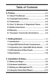
Contents
About this User’s Guide .............................................. 1
1
Your SpeedTouch™ ...................................................... 3
1.1
SpeedTouch™ Features .................................................................. 4
1.1.1
Hardware Specifications .................................................................................. 5
1.1.2
Software Features .......................................................................................... 6
1.2
SpeedTouch™ LED Behaviour ........................................................ 9
1.3
How to Access your SpeedTouch™.............................................. 11
1.3.1
Access via the Web Interface......................................................................... 12
1.3.2
Access via CLI ............................................................................................. 13
1.3.3
Access via FTP ............................................................................................ 15
1.3.4
Remote Assistance ....................................................................................... 18
2
Local Network Setup .................................................. 19
2.1
Wired Ethernet ............................................................................. 20
2.2
Wireless Ethernet ......................................................................... 21
2.2.1
Wireless Basics ............................................................................................ 22
2.2.2
Connecting First-time Wireless Clients............................................................. 24
2.2.3
Wireless Security.......................................................................................... 27
2.2.4
Connecting Additional Wireless Clients............................................................ 29
2.2.5
Extending the Range of Your Wireless Network ................................................ 31
3
Internet Connectivity Dial-In Clients ......................... 33
3.1
SpeedTouch™ Web Pages ............................................................ 35
3.2
IGD Control Agent ....................................................................... 37
E-DOC-CTC-20050429-0104 v1.0
i
Contents
ii
3.3
MS Windows XP BroadBand Connection ..................................... 39
3.4
Mac OS X PPPoE Dial-in Client .................................................... 43
4
Basic Configuration .................................................... 45
4.1
Navigation.................................................................................... 46
4.1.1
Menu .......................................................................................................... 47
4.1.2
Language Bar ............................................................................................... 48
4.1.3
Navigation Bar ............................................................................................. 49
4.1.4
Notification Area .......................................................................................... 50
4.1.5
Tasks.......................................................................................................... 51
4.2
Home ............................................................................................ 52
4.3
SpeedTouch ................................................................................. 53
4.3.1
Information .................................................................................................. 54
4.3.2
SpeedTouch™ Easy Setup .............................................................................. 55
4.3.3
Restart........................................................................................................ 56
4.3.4
Configuration ............................................................................................... 57
4.3.5
Backup & Restore......................................................................................... 58
4.3.6
Reset to Factory Defaults .............................................................................. 59
4.3.7
Event Logs .................................................................................................. 60
4.3.8
Update........................................................................................................ 61
4.4
Broadband Connection................................................................. 62
4.4.1
Connectivity Check....................................................................................... 63
4.4.2
DSL Connection ........................................................................................... 64
4.4.3
Internet Services .......................................................................................... 65
4.4.4
Internet Service Settings ............................................................................... 66
E-DOC-CTC-20050429-0104 v1.0
Contents
4.5
Toolbox ........................................................................................ 67
4.5.1
Remote Assistance ....................................................................................... 68
4.5.2
Game & Application Sharing .......................................................................... 69
4.5.3
Defined Games & Applications ....................................................................... 70
4.5.4
Game or Application Definition ....................................................................... 71
4.5.5
New Game or Application .............................................................................. 72
4.5.6
Web Site Filtering ......................................................................................... 73
4.5.7
Web Filtering Activation ................................................................................ 76
4.5.8
Content Level .............................................................................................. 77
4.5.9
New Content Level ....................................................................................... 78
4.5.10
Firewall ....................................................................................................... 80
4.5.11
Intrusion Detection ....................................................................................... 81
4.5.12
Dynamic DNS .............................................................................................. 82
4.5.13
User Management ........................................................................................ 83
4.5.14
Edit User ..................................................................................................... 84
4.5.15
Change Default User ..................................................................................... 85
4.5.16
Add User..................................................................................................... 86
4.6
Office Network ............................................................................ 87
4.6.1
Devices ....................................................................................................... 88
4.6.2
Device Settings ............................................................................................ 89
4.6.3
Assign Public IP ........................................................................................... 90
4.6.4
Wireless Device Settings ............................................................................... 91
4.6.5
Access Point Settings ................................................................................... 92
4.6.6
Configuring WDS.......................................................................................... 95
4.6.7
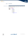
Interfaces .................................................................................................... 96
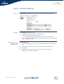
4.6.8
Interface Settings ......................................................................................... 97
4.6.9
DHCP Pool................................................................................................... 98
5
Expert Configuration ................................................ 101
5.1
Home .......................................................................................... 103
E-DOC-CTC-20050429-0104 v1.0
iii
Contents
iv
5.2
SpeedTouch™............................................................................. 104
5.2.1
Easy Setup ................................................................................................ 105
5.2.2
System Information .................................................................................... 106
5.2.3
Connections .............................................................................................. 108
5.2.4
Diagnostics................................................................................................ 109
5.2.5
Syslog ...................................................................................................... 110
5.2.6
System Update .......................................................................................... 112
5.2.7
SpeedTouch™ Services ................................................................................ 115
5.2.8
SNTP ........................................................................................................ 118
5.2.9
SLA .......................................................................................................... 119
5.2.10
Add-on...................................................................................................... 122
5.3
IP Router .................................................................................... 123
5.3.1
IP Addresses.............................................................................................. 124
5.3.2
Expressions ............................................................................................... 125
5.3.3
Classification ............................................................................................. 127
5.3.4
IP Routing ................................................................................................. 129
5.3.5
RIP ........................................................................................................... 130
5.3.6
NAT ......................................................................................................... 131
5.3.7
IP QoS ...................................................................................................... 133
5.4
Connections ............................................................................... 135
5.4.1
ATM ......................................................................................................... 136
5.4.2
Routed PPPoE ............................................................................................ 138
5.4.3
Routed PPPoA............................................................................................ 140
5.4.4
Routed PPPoI ............................................................................................. 142
5.4.5
Bridged Ethernet......................................................................................... 144
5.4.6
Routed Ethernet ......................................................................................... 147
5.4.7
Routed IPoA .............................................................................................. 148
5.4.8
PPTP-to-PPP Relay ...................................................................................... 149
5.4.9
Virtual LAN................................................................................................ 150
5.5
Local Networking....................................................................... 151
5.5.1
DHCP........................................................................................................ 152
5.5.2
DNS ......................................................................................................... 157
5.5.3
Managed Switch ........................................................................................ 158
5.5.4
Wireless .................................................................................................... 160
5.6
Firewall ...................................................................................... 167
5.6.1
Policy........................................................................................................ 168
5.6.2
Log........................................................................................................... 171
E-DOC-CTC-20050429-0104 v1.0
Contents
5.7
VPN ............................................................................................ 172
5.7.1
LAN to LAN ............................................................................................... 173
5.7.2
VPN Client................................................................................................. 174
5.7.3
VPN Server................................................................................................ 175
5.7.4
Certificates ................................................................................................ 176
5.7.5
Advanced .................................................................................................. 177
5.7.6
Debug ....................................................................................................... 178
5.8
SIP PBX ...................................................................................... 179
6
Software Keys ........................................................... 181
7
Software Upgrade..................................................... 183
7.1
Embedded Update Page ............................................................. 184
7.2
Upgrade Wizard on Setup CD..................................................... 186
7.3
Upgrade via a BOOTP/TFTP Server............................................. 189
8
Troubleshooting........................................................ 191
8.1
General SpeedTouch™ Troubleshooting .................................... 192
8.1.1
Wired Ethernet Troubleshooting.................................................................... 193
8.1.2
Wireless Ethernet Troubleshooting ................................................................ 194
8.1.3
Upgrade Troubleshooting............................................................................. 195
8.2
UPnP™ on Windows XP Systems............................................... 197
8.3
Reset to Factory Defaults .......................................................... 199
E-DOC-CTC-20050429-0104 v1.0
v
Contents
vi
E-DOC-CTC-20050429-0104 v1.0
About this User’s Guide
About this User’s Guide
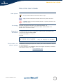
Used Symbols
A note provides additional information about a topic.
A tip provides an alternative method or shortcut to perform an action.
!
Terminology
Typographical
Conventions
A caution warns you about potential problems or specific precautions that
need to be taken.
Generally, the SpeedTouch™605(i), the SpeedTouch™608(i), the
SpeedTouch™608(i) WL, and the SpeedTouch™620(i) will be referred to as
SpeedTouch™ in this User’s Guide.
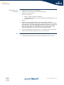
In interactive input and output, typed input is displayed in a bold font and
commands are displayed like this.
Comments are added in italics.
Example:
=>language list
CODE LANGUAGE VERSION FILENAME
en* english 4.2.0.1 <system>
Documentation and
software updates
Only one language is available
THOMSON continuously develops new solutions, but is also committed to improve
its existing products.
For more information on THOMSON's latest technological innovations, documents
and software releases, visit us at:
www.speedtouch.com
E-DOC-CTC-20050429-0104 v1.0
1
About this User’s Guide
2
E-DOC-CTC-20050429-0104 v1.0
Chapter 1
Your SpeedTouch™
1 Your SpeedTouch™
Introduction
With the SpeedTouch™605(i) and SpeedTouch™608(i) Business DSL Routers and the
SpeedTouch™608 WL(i) and SpeedTouch™620(i) Wireless Business DSL Routers you
can build a secure small (home-)office network, seamlessly connecting wired and
wireless devices and surf the Internet at high speed, all combined in one device.
Installation
For more information on how to set up your SpeedTouch™, installation and wiring
and how to do a first Internet connection setup, refer to the provided Installation and
Setup Guide.
Contents
Safety instructions
E-DOC-CTC-20050429-0104 v1.0
This User’s Guide will assist you in configuring your SpeedTouch™.
Before connecting the SpeedTouch™, please read the SpeedTouch™ Quick Installation
Guide and the Safety Instructions and Regularity Notices.
3
Chapter 1
Your SpeedTouch™
1.1 SpeedTouch™ Features
Introduction
Your SpeedTouch™ offers you a wide range of outstanding features.
In this section you will find a comprehensive overview of the:
4
Hardware Specifications
Software Features
E-DOC-CTC-20050429-0104 v1.0
Chapter 1
Your SpeedTouch™
1.1.1 Hardware Specifications
Router
Physical interfaces
Integrated multi-mode ADSL modem, supporting:
ADSL over POTS for a SpeedTouch™ ADSL/POTS variant)
ADSL over ISDN for a SpeedTouch™ ADSL/ISDN variant)
ADSL/RE-ADLS2/ADSL2/ADSL2+ for both ADSL over POTS and ADSL over
ISDN
WAN:
LEDs
Reset button
Association button
Wireless performance
Memory and CPU
Cardbus
E-DOC-CTC-20050429-0104 v1.0
One RJ-11 port for ADSL/POTS or ADSL/ISDN connection
Integrated ISDN Modem S0 interface (in case of a SpeedTouch™608 WL/
620)
LAN:
Four RJ-45 ports for managed 10/100Base-T Half-/Full-duplex autosensing MDI/MDI-X Ethernet switch
Wireless LAN: IEEE 802.11b/g Wi-Fi compliant access point on the
SpeedTouch™608 WL/620
LED indicators for all interfaces
One programmable recessed reset button for restoring the factory default settings
One push button for wireless association and registration on the
SpeedTouch™608 WL/620
On the SpeedTouch™608 WL/620:
Typical indoor coverage: 60m
Dynamic rate switching
Manual / Automatic channel selection
Manual / Automatic selection of pure 802.11g, pure 802.11b or mixed mode
(802.11b/g) network
Wireless Distribution System (WDS)
WPA-PSK / WEP data encryption
16 MB flash
32 MB SDRAM
Memory and processor load counters
On SpeedTouch™608 WL/620:
Power requirement
PCMCIA/CardBus plug-in slot for future extension: IPSec acceleration card,
PSTN back-up card, GPRS back-up card, ..
Power supply: 18V AC, 1000mA with patent-pending power-cord lock to avoid
accidental power plug-out
5
Chapter 1
Your SpeedTouch™
1.1.2 Software Features
ADSL compliance
ATM features
Bridging features
Routing features
6
If POTS in overlay: G. handshake, Full Rate ADSL, G.dmt, G.lite (splitterless
ADSL), ADSL2, RE-ADSL and ADSL2+
If ISDN in overlay: G.handshake, G.dmt, ADSL2, RE-ADSL and ADSL2+
Up to 16 simultaneous PVCs, allowing multiple simultaneous destinations
ATM QoS per PVC: CBR, VBR-rt, VBR-nrt, UBR
Service monitoring through ITU-T I.620 F4/F5 loopback, alarms (AIS / RDI) and
continuity checks
ATM PING command (loopback cells) and continuity check generator mode
RFC 1483 / 2684 multiprotocol encapsulation over AAL5 / ATM: both LLC /
SNAP and VC-based multiplexing supported
Multiport self-learning transparent bridge per IEEE 802.1D for LAN interconnect
Remote bridge ports are isolated from each other
Pre-defined bridge filters to WAN (no filter, no CPE-to-WAN broadcast, PPPoE
only) and to LAN (no filter, multicast filter)
Multi-port (up to 16 PVCs) router
Static routing, automatic routes (PPP, LAN)
IP address multi-homing
Packet classified routing:
Label classification of packet streams based on source and destination IP
address, source and destination port, type of service / diffserv bits,
protocol, source interface
Forwarding of packet streams based on the label classification
Type of service / DSCP marking based on the label classification
IGMPv1/v2/v3 forwarding
TCP (RFC793), UDP (RFC768), ICMP (RFC792), IPv4 router (RFC1812)
Dynamic routing RIPv1 (RFC 1058) and RIPv2 (RFC 1723 / 2453), configurable
per interface
E-DOC-CTC-20050429-0104 v1.0
Chapter 1
Your SpeedTouch™
Networking services
Security
Configuration
E-DOC-CTC-20050429-0104 v1.0
UPnP with NAT traversal capability:
enables game technologies (Xbox live, Direct X, and many others)
enables conferencing functions of Microsoft Messenger
Transparent bridging (IEEE802.1D)
PPPoE routing/bridging with integrated PPP Relay
PPPoA routing, PPPoA-to-PPTP relaying
Hyper-NAT with virtual server mapping (for instance for Web, FTP, Mail
servers) and ALGs (such as NetMeeting, MSN Messenger, VPN passthrough,
and others)
Quality of Service:
ATM QoS per PVC: CBR, VBR-rt, VBR-nrt, UBR
IP QoS
Managed Ethernet Switch with VLAN, DMZ, mirroring
Service Level Agreement services
Integrated Dynamic DNS client
PAP (RFC1334), CHAP (RFC1994) for PPP session
Integrated Stateful Inspection Firewall, Intrusion Detection
Website Filtering, URL Filtering
Wireless security on SpeedTouch™608 WL/620:
64/128bit WEP encryption, WPA-PSK
Wireless client registration/access control (with physical push button)
Multi-level SpeedTouch™ access policies, Digest Authentication
SSH, SSL
Embedded IPSec Software Module (on SpeedTouch™608/608 WL/620)
Dedicated support for provider-provisioned PE-based MPLS networks
Home Install Wizard, Easy Setup wizard
Intuitive web-based GUI (HTTP/HTTPs)
Advanced configuration via telnet/SSH, via the web-based GUI and serial
console - Command Line Interface (CLI)
Remote management access control
7
Chapter 1
Your SpeedTouch™
Management and
monitoring
VoIP
Multi-level user protection, Event logging
DHCP server, client and relay, DHCP-to-PPP spoofing
DNS server, client and relay
Time synchronization:
SNTPv1, SNTPv2, SNTPv3 and SNTPv4
integrated Real-Time Clock in case of SpeedTouch™608 WL/620 (for nonvolatile time-of-day)
Syslog
SNMPv1 support for:MIB II (RFC1213/2011/2012/2013), traps MIB
(RFC1215), bridge MIB (RFC1286/1493), ATM TC MIB (RFC2514), ATM MIB
(RFC1695/2515), ADSL MIB (RFC2662)/SHDSL MIB (RFC3276), Ethernet MIB
(RFC1398/1623/1643/1650/2358/2665), Medium Attachment Units MIB
(RFC1515/2239/2668), interface MIB (RFC1229/1573/2233/2863), IPSec
MIB, RMON MIB (RFC1757), PING & Traceroute MIB (RFC2925)
Firmware upgradeable via web or via FTP, or via upgrade wizard on Setup CD
Dual firmware storage (Active/Passive) for fail-proof roll-back
On the SpeedTouch™620 (under Software Module activation key):
8
Embedded SIP PBX functionality including SIP Registrar and Proxy server.
E-DOC-CTC-20050429-0104 v1.0
Chapter 1
Your SpeedTouch™
1.2 SpeedTouch™ LED Behaviour
The SpeedTouch™ is equipped with a number of LEDs on its front panel, indicating
the state of the device during normal operation.
t
rne
Inte
N
DSL
ISD
g-In
Plu
AN
WL
ern
Eth
Pow
er
et
Front panel LEDs
Following table shows the meaning of the different LEDs:
Indicator
Description
Name
Colour
State
Power
Green
On
Power on, normal operation
Red
On
Power on, self-test failed, indicating
device malfunction
Orange
On
Bootloader active
Off
Ethernet
Green
Power off
Flashing
Ethernet activity
On
Ethernet connection, no activity
Off
WLAN
Green
Amber
Red
No Ethernet connection
Flashing
Wireless activity, WPA encryption
On
No wireless activity, WPA encryption
Flashing
Wireless activity, WEP encryption
On
No wireless activity, WEP encryption
Flashing
Wireless activity, no security
On
No wireless activity, no security
Off
Plug-in
Green
Off
E-DOC-CTC-20050429-0104 v1.0
WLAN disabled
Flashing
Data passing through the cardbus
On
Cardbus is connected, no data
passing through
Cardbus is not connected
9
Chapter 1
Your SpeedTouch™
Indicator
Description
Name
Colour
State
ISDN
Green
Flashing
ISDN activity
On
ISDN line connected, no activity
Off
DSL
Green
No ISDN line
Flashing
Pending DSL line synchronisation
On
DSL line synchronised
Off
Internet
Green
Red
No DSL line
Flashing
Internet activity
On
Internet connectivity, no activity
On
Internet connection setup failed
Off
Ethernet LEDs
No Internet connection
A LED may be provided per Ethernet port to indicate link integrity (or activity).
Depending on the SpeedTouch™ product you are using, a second LED (A) may be
provided to indicate the 10/100Base-T selection:
A
B
Indicator
Description
Name
A
(Optional)
B
10
LED Status
Integrity
(Activity)
10/100Base-T
Off
No connection on this port
On
Ethernet link up
Flashing
Data is flowing from/to this port
Off
10Base-T Ethernet connection
On
100Base-T Ethernet connection
E-DOC-CTC-20050429-0104 v1.0
Chapter 1
Your SpeedTouch™
1.3 How to Access your SpeedTouch™
Access methods
Your SpeedTouch™ is accessible in one of following ways:
Access Method
Can be used to:
Web
Configure your SpeedTouch™ via HTTP or
HTTPS.
For more information, see “1.3.1 Access via
the Web Interface” on page 12.
E-DOC-CTC-20050429-0104 v1.0
Command Line Interface (CLI)
Fine tune your SpeedTouch™ configuration.
For more information, see “1.3.2 Access via
CLI” on page 13.
File Transfer Protocol (FTP)
Backup and restore data on your SpeedTouch™.
For more information, see “1.3.3 Access via
FTP” on page 15.
Remote Assistance
Allow a remote user to help you configuring
your SpeedTouch™.
For more information, see “1.3.4 Remote
Assistance” on page 18.
11
Chapter 1
Your SpeedTouch™
1.3.1 Access via the Web Interface
Procedure
To access the SpeedTouch™ via the web interface:
1
Open a web browser.
2
In the address bar type your SpeedTouch™’s IP address or DNS host name, by
default that is ‘http://speedtouch.lan’ or ‘192.168.1.254’.
You can access the pages via the http protocol. For remote assistance
the secure version, https, in combination with certificates is used;
provide your ISP with the https link, user name and password before
he can log on to the pages. For more information, see “1.3.4 Remote
Assistance” on page 18.
3
As a result the SpeedTouch™ Home page appears, from where you can navigate
to all the configurable aspects of the SpeedTouch™.
For more information on the web pages, see “4 Basic Configuration” on page 45.
12
E-DOC-CTC-20050429-0104 v1.0
Chapter 1
Your SpeedTouch™
1.3.2 Access via CLI
Command Line
Interface (CLI)
You can access the Command Line Interface (CLI) via:
The embedded Expert pages. For more information, see “5 Expert
Configuration” on page 101.
A Telnet session
This requires that TCP/IP connectivity exists between the host from which the
Telnet session is opened and the SpeedTouch™. Your SpeedTouch™ and the
connected PC must have an IP address in the same subnet.
The serial ‘Console’ interface
Quote site commands (over FTP)
For more information, see “ Quote site command” on page 17.
For information on CLI commands, see the SpeedTouch™ CLI Reference Guide.
E-DOC-CTC-20050429-0104 v1.0
13
Chapter 1
Your SpeedTouch™
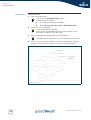
Telnet session
Proceed as follows:
1
Open a telnet application.
You can use the Command Prompt window.
In Windows XP for instance:
2
1
On the Windows task bar, click Start.
2
Select (All) Programs > Accessories > Command Prompt.
Connect to your SpeedTouch™. .
In the Command Prompt window:
At the prompt, type telnet followed by the IP address of your
SpeedTouch™ (default is 192.168.1.254).
3
Enter your SpeedTouch™ security user name and password.
The default user is ‘Administrator’ and the default password is blank.
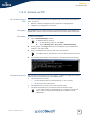
4
As soon as you’ve opened a session to the CLI, the SpeedTouch™ banner is
displayed, followed by the CLI prompt, as shown in the example below:
Username : Administrator
----------------------------------------------------------------------*
______ SpeedTouch
*
___/_____/\
*
/
/\\ Version 5.3
*
_____/__
/ \\
*
_/
/\_____/___ \ Copyright (c) 1999-2005,
*
//
/ \
/\ \
THOMSON
*
_______//_______/
\
/ _\/______
*
/
/ \
\
/
/ /
/\
*
__/
/
\
\ /
/ /
/ _\__
* / /
/
\_______\/
/ /
/ /
/\
* /_/______/___________________/ /________/ /___/ \
* \ \
\
___________
\ \
\ \
\ /
* \_\
\ /
/\
\ \
\ \___\/
*
\
\/
/ \
\ \
\ /
*
\_____/
/
\
\ \________\/
*
/__________/
\
\ /
*
\
_____ \
/_____\/
*
\ /
/\ \
/___\/
*
/____/ \ \ /
*
\
\ /___\/
*
\____\/
----------------------------------------------------------------------{Administrator}=>
14
E-DOC-CTC-20050429-0104 v1.0
Chapter 1
Your SpeedTouch™
1.3.3 Access via FTP
File Transfer Protocol
(FTP)
File system
FTP session
You can access the file system of the SpeedTouch™ via the File Transfer Protocol
(FTP), in order to:
Restore or backup configuration files, templates or language packs.
Upgrade your configuration or firmware.
The SpeedTouch™ file system is stored on nonvolatile memory, and contains the
SpeedTouch™ software, service template files and (optionally) default setting files.
To open an FTP session:
1
Open a Command Prompt window.
In Windows XP for instance:
1
On the Windows task bar, click Start.
2
Select (All) Programs > Accessories > Command Prompt.
2
At the prompt, type ftp followed by the IP address of your SpeedTouch™
(default is 192.168.1.254).
3
Enter your SpeedTouch™ security user name and password.
The default user is ‘Administrator’ and the default password is blank.
4
File system structure
The example below shows an FTP session to the SpeedTouch™ file system:
The structure of the file system is very simple: It consists of a single root directory
called root and two subdirectories called active and dl.
The root directory contains:
all the necessary files for the SpeedTouch™ to boot correctly
the active and the dl directories
The active directory contains the active software image.
The dl (download) directory contains the passive software image.
If you made changes to the SpeedTouch™ configuration and saved
them, a user.ini configuration settings file is created in the dl
subdirectory.
E-DOC-CTC-20050429-0104 v1.0
15
Chapter 1
Your SpeedTouch™
File system access
rights
Common FTP
commands
On the different directories you have following privileges:
Directory
Access rights
root
NO read/write
active
read-only
dl
read/write
Depending on the access rights you have on a directory, you can use one of
following commands:
Command...
You can use to...
cd
access another directory than the one currently open.
Example: ftp>cd dl.
dir
list the directory files.
Example: ftp>dir.
bin
set the transfer mode to ‘binary’.
hash
turn on the hashing option.
put
upload files.
Example: ftp>put C:/MyBackupFiles/user.ini.
A configuration file must be uploaded to the dl directory.
get
download files.
Example: ftp>get user.ini.
Downloading the configuration file must be done from the dl
directory.
16
delete
delete files.
bye
quit FTP.
E-DOC-CTC-20050429-0104 v1.0
Chapter 1
Your SpeedTouch™
FTP file transfer
To allow correct file transfers, set the transfer mode to “binary”: At the ftp prompt,
type bin and press Enter.
Turn on the hashing option to see the progression of the file transfer: At the
ftp prompt type hash and press Enter.
Example:
/home/doejohn{1}$ftp 192.168.1.254
Connected to 192.168.1.254
220 Inactivity timer = 120 seconds. Use 'site idle <secs>' to change.
Name (192.168.1.254:doejohn):
331 SpeedTouch™ (00-90-D0-01-02-03) User 'doejohn' OK. Password requir
ed.
Password : ######
330 OK
ftp>
ftp>bin
200 TYPE is now 8-bit binary
ftp>
ftp>hash
200Hash mark printing on (8192 bytes/hash mark).
ftp>cd dl
250 Changed to /dl
ftp>put C:\user.ini
200 Connected to 192.168.1.10 port 1271
150 Opening data connection for user.ini
226 File written successfully
ftp: 256 bytes sent in 0,000Seconds 256000,000Kbytes/sec.
ftp>
Quote site command
All the CLI commands can be executed from within an FTP session. Only complete
CLI commands (in other words, the complete command syntax with all the
parameters already specified) can be executed.
Example: To execute the CLI command :software cleanup: At the FTP prompt
type ‘quote site software cleanup’ and press Enter.
ftp> quote site software cleanup
200200 CLI command "software cleanup" executed
ftp>
For more information on CLI commands, see the CLI Reference Guide.
E-DOC-CTC-20050429-0104 v1.0
17
Chapter 1
Your SpeedTouch™
1.3.4 Remote Assistance
Remote access
Enabling remote access
You can make your SpeedTouch accessible from the Internet with regard to remote
support. This way, you can allow your helpdesk to access your SpeedTouch™
remotely.
To enable remote assistance:
1
Go to the SpeedTouch™ pages, as described in “1.3.1 Access via the Web
Interface” on page 12.
2
In the menu select Toolbox > Remote Assistance.
3
Click Enable Remote Assistance.
4
Provide the following parameters to your helpdesk:
5
URL (the HTTPS link)
User name
Password
Your ISP is now able to access your SpeedTouch™ via the secure HTTPs link in
combination with the provided certificate (a secure authentication mechanism).
For security reasons, after 20 minutes of inactivity, or on reboot, Remote
Assistance will be automatically disabled.
Disabling remote
access
18
To disable remote assistance:
1
Go to the SpeedTouch™ pages, as described in “1.3.1 Access via the Web
Interface” on page 12.
2
In the menu select Toolbox > Remote Assistance.
3
Click Disable Remote Assistance.
E-DOC-CTC-20050429-0104 v1.0
Chapter 2
Local Network Setup
2 Local Network Setup
Introduction
Device settings
E-DOC-CTC-20050429-0104 v1.0
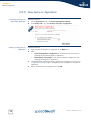
The SpeedTouch™ offers you following local networking solutions:
Wired Ethernet
Wireless Ethernet
Once you’ve connected a device, you are able to personalise its settings:
1
Go to the SpeedTouch™ web pages.
2
In the menu select Home Network > Devices.
3
Click the name of your device, or if the device’s settings haven’t been
personalised yet, click the MAC address of the device.
4
On the top right, click Configure.
5
Now you can change the device’s name, lock its IP address and assign
applications and services to the device.
19
Chapter 2
Local Network Setup
2.1 Wired Ethernet
Local network
The Ethernet ports on the backpanel allow you to connect the SpeedTouch™ to an
existing 10 or 100 Base-T Ethernet network or one (or more) computer(s) with
installed Ethernet card.
Using the SpeedTouch™ Ethernet switch, you can create a local Ethernet network of
up to four devices, without needing extra networking devices.
In the SpeedTouch™ package, a yellow full-wired straight-through RJ-45/RJ45 Ethernet cable is included.
Standard wiring
procedure
Use the yellow Ethernet cable provided to wire your computer's Ethernet port to one
of the SpeedTouch™'s Ethernet ports.
The Ethernet cable can also be used to wire any Ethernet port of your SpeedTouch™
to an external hub or switch.
Please follow the installation instructions supplied with the external hub or
switch for connections and Ethernet cabling.
Ethernet link check
Device settings
LED indicators allow you to check your Ethernet. See “1.2 SpeedTouch™ LED
Behaviour” on page 9 for more information.
Once you’ve connected a device, you are able to personalise its settings.
For more information, see “ Device settings” on page 19.
Managed Ethernet
switch
Your SpeedTouch™ intelligently switches data between the devices on your LAN,
using priority queuing to ensure that higher priority messages are delivered first and
in real-time. This feature maximizes your network performance.
The managed Ethernet switch allows you to configure a Virtual Local Area Network
(VLAN), group ports or isolate a port, configure secure channel connections, define
Quality of Service (QoS), and you can configure port mirroring, allowing monitoring
from one port to another.
You can configure the managed Ethernet switch manually using CLI (For more
information, see the SpeedTouch™ CLI Reference Guide) or on the expert web pages
(see“5.5.3 Managed Switch” on page 158).
20
E-DOC-CTC-20050429-0104 v1.0
Chapter 2
Local Network Setup
2.2 Wireless Ethernet
Introduction
The SpeedTouch™ 608 WL/620Wi-Fi® certified IEEE 802.11g compliant wireless
access point allows multiple computers to connect wirelessly to your local network
over the SpeedTouch™ Wireless LAN environment. The SpeedTouch™ is backward
compatible with IEEE 802.11b, which means 802.11b and 802.11g devices can
coexist in the same wireless network.
The Wireless Distribution System (WDS) on your SpeedTouch™ allows you to extend
the range of your wireless network. To be able to use WDS, you will need to
introduce an additional WDS-enabled access point into your wireless network.
To be able to connect the computers, make sure that a wireless client adapter
(WLAN client) is installed on each computer you want to connect via the WLAN.
Wireless client
requirements
All wireless client adapters compliant to 802.11g and/or 802.11b, will be able to
communicate with the SpeedTouch™ and other members of the SpeedTouch™
(W)LAN environment. However, be aware that only 802.11g compliant wireless
clients are able to gain full profit of the 54 Mb/s (Max) bandwidth delivered by the
SpeedTouch™.
It is highly recommended to use only wireless client adapters that are Wi-Fi™ certified
to ensure smooth interoperability with the SpeedTouch™’s WLAN.
E-DOC-CTC-20050429-0104 v1.0
21
Chapter 2
Local Network Setup
2.2.1 Wireless Basics
Introduction
In this section some key wireless concepts are explained.
802.11b/g
802.11b is an IEEE standard, operating at 2,4 GHz at a speed of up to 11 Mb/s.
802.11g, a newer IEEE standard also operating at 2,4 GHz, gives you up to 54 Mb/s
speed, more security and better performance.
Wireless Fidelity
Access Point
The Wi-Fi certification ensures that your SpeedTouch™ will interoperate with any WiFi certified 802.11g and 802.11b compliant wireless device.
The SpeedTouch™ Wireless LAN Access Point (AP) behaves as a networking hub
allowing to wirelessly interconnect several devices to the local (W)LAN and to
provide access to the Internet.
Network Name or SSID
The WLAN's 'radio' link is a shared medium. As no physical connection exists
between the SpeedTouch™ and wireless clients, a name must be given to allow
unique identification of your WLAN radio link. This is done by the Service Set ID
(SSID), also referred to as Network Name. Wireless clients must be part of this SSID
environment in order to be able to communicate with other clients on the (W)LAN including the SpeedTouch™.
Radio channels
The 802.11g standard allows several WLAN networks using different radio channels
to be co-located. The SpeedTouch™ supports multiple radio channels and is able to
select the best radio channel at each start-up.
You can choose to set the channels automatically or manually.
The different channels are overlapping. To avoid interference with another
access point, make sure that the separation (in terms of frequency) is as
high as possible. It’s recommended to keep at least 3 channels between 2
different access points.
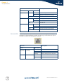
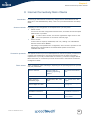
The SpeedTouch™ supports all channels allowed for wireless networking. However,
depending on local regulations, the number of channels actually allowed to be used
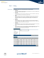
may be additionally restricted, as shown in the table below:
22
Regulatory Domain
Allowed Radio Channels
China
1 to 13
Europe
1 to 13
Israel
5 to 8
Japan
1 to 14
Jordan
10 to 13
Thailand
1 to 14
USA
1 to 11
E-DOC-CTC-20050429-0104 v1.0
Chapter 2
Local Network Setup
Antennas
Direct the external antenna to allow optimization of the wireless link. If for example
the antenna is erect, wireless links in the horizontal plane are favoured. Please note
that the antenna characteristics are influenced by the environment, that is by
reflections of the radio signal against walls or ceilings. It is advisable to use the
received signal strength as indicated by the wireless client manager to optimize the
antenna position for the link to a given client.
Concrete walls will die down the radio signal strength and thus affect the
connection.
E-DOC-CTC-20050429-0104 v1.0
23
Chapter 2
Local Network Setup
2.2.2 Connecting First-time Wireless Clients
Wireless default
settings
After every Reset-to-Defaults, the SpeedTouch™ wireless access point configuration
is returned to its initial default settings.
These default settings are:
Security level is low (security disabled) for an easy first use, meaning the data
will not be encrypted. Wireless security settings are described in
“2.2.3 Wireless Security” on page 27.
The SpeedTouch™ is broadcasting its network name (SSID).
This default network name (SSID) is printed on the identification label located
on the bottom of your SpeedTouch™ and is unique for each device. It consists
of the concatenation of the word “SpeedTouch” and 6 hexadecimal characters,
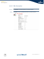
without any spaces, for example SpeedTouch123456.
The radio channel number is set to ‘automatically scan for the best radio
channel’.
Registration is not activated. New stations are allowed automatically. The
Access Control List is open and empty. No wireless client will be denied access
to the SpeedTouch™ based on its physical hardware address.
The default wireless settings may differ from the settings listed above
depending on your Service Provider’s requirements. If this is the case, refer
to the installation/configuration instructions provided by your Service
Provider.
Preparing first-time
wireless clients
Make sure that:
The SpeedTouch™ is powered on and ready for service.
The SpeedTouch™ is in its default configuration.
If needed, reset the SpeedTouch™ to its default configuration (See “8.3 Reset
to Factory Defaults” on page 199 for more information).
Configuring first-time
wireless clients
A wireless client adapter is installed on your computer.
The wireless client adapter’s IP configuration is set to dynamically obtain its IP
configuration (DHCP) - this is usually the default. For more information, see the
documentation of your wireless client adapter.
The wireless client must be correctly configured for the default network name. As
the SpeedTouch™ broadcasts its network name to the wireless clients, you can select
the SpeedTouch™ wireless network from a list of available networks. Depending on
your wireless client a wireless icon may become green or a message similar to the
following may pop up: “Successfully joined Wireless network SpeedTouch123456”.
Some wireless clients do not automatically join a wireless network. If so,
follow the instructions for the wireless client software to initiate association.
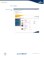
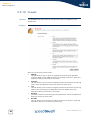
First-time association
example
24
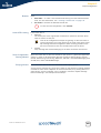
In the example below is shown how the SpeedTouch™ wireless network is presented
towards an MS Windows XP Service Pack 2 system:
E-DOC-CTC-20050429-0104 v1.0
Chapter 2
Local Network Setup
To associate your wireless client to the SpeedTouch™:
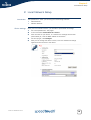
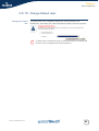
1
Click the network icon in the notification area:
2
The Wireless Network Connection window appears:
In the Choose a wireless network list, select the SpeedTouch™ wireless
network and click Connect.
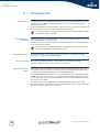
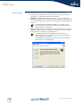
3
Following window appears:
Click Connect Anyway.
4
Your computer is now connected to the SpeedTouch™ wireless network.
For other Operating Systems the wireless client will in most cases be
configured via dedicated client managers.
E-DOC-CTC-20050429-0104 v1.0
25
Chapter 2
Local Network Setup
Wireless device
settings
Once you’ve connected a device, you are able to personalise its settings.
For more information, see “ Device settings” on page 19.
To add a wireless device to the Access Control List (ACL), select Allowed on
WLAN.
26
E-DOC-CTC-20050429-0104 v1.0
Chapter 2
Local Network Setup
2.2.3 Wireless Security
Introduction
Since the SpeedTouch™ wireless environment is a radio environment, precautions
must be taken to ensure that your wireless network is safe from malicious intruders.
To secure your wireless network, following wireless access point settings can be
personalised:
Security settings
Network Name (SSID)
Your Network Name (SSID)
ACL setting
Data encryption
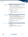
To personalise the wireless security settings on your SpeedTouch™:
1
Go to the SpeedTouch™ web pages.
2
In the menu select Home Network.
3
Click your WLAN.
4
On the top right, click Configure.
5
On the Wireless Access Point page, you can modify the Security settings.
On the Wireless Access Point page, you can give a new name to your Network
Name (SSID).
Under Security, you can clear Broadcast Network Name (SSID), to prohibit the
Network Name from being broadcasted.
Access Control List
(ACL)
The SpeedTouch™ features a managed Access Control List (ACL) and a physical
registration mechanism in the form of the Association / Registration button on the
back panel of your SpeedTouch™.
On the Wireless Access Point page, you have following options for the ACL: New
stations are
E-DOC-CTC-20050429-0104 v1.0
Allowed (automatically): All new stations can access the SpeedTouch™.
Allowed (via registration): Only allowed stations in the ACL have access.You
can add new stations via the Association / Registration button. For more
information, see “ Registering clients via association button” on page 30.
Not allowed: Only allowed stations in the ACL have access.
27
Chapter 2
Local Network Setup
Data encryption
To setup wireless connectivity, you can choose different levels of security:
Low (Security disabled, the default): No security; the data will not be
encrypted, no authentication process will be used.
Medium: Use WEP (Wired-Equivalent Privacy) to encrypt the traffic
between the SpeedTouch™ and the clients by sharing a pre-defined 64-bit
or a 128-bit Network key for secure communication with legacy 802.11b
clients.
The default 64 bits hexadecimal WEP key is printed on the
identification label located at the bottom of the SpeedTouch™
and is unique for each device.
High: Use WPA-PSK (Wi-Fi Protected Access Pre-Shared Key) encryption,
the highest form of security available, but make sure that your wireless
client and client manager are compatible with it.
The default WPA-Personal passphrase is printed on the
identification label located at the bottom of the SpeedTouch™
and is unique for each device.
The WPA-Personal passphrase must consist of 8 to 63 ASCII
characters or 8 to 64 HEX digits.
28
E-DOC-CTC-20050429-0104 v1.0
Chapter 2
Local Network Setup
2.2.4 Connecting Additional Wireless Clients
Preconditions
Security issues
Registering wireless
clients
Registering clients via
web pages
E-DOC-CTC-20050429-0104 v1.0
Make sure that:
The SpeedTouch™ is powered on and ready for service.
The SpeedTouch™ has been configured as DHCP server (default).
The wireless client adapters have been installed on all computers you want to
connect to the WLAN.
Depending on the personalised wireless settings:
Make sure to use the same encryption or security level on the client as on your
SpeedTouch™. If for instance WPA-PSK is enabled on the SpeedTouch™, you
must also configure the wireless client to use WPA-PSK and configure the same
WPA-PSK passphrase.
In case the Network Name (SSID) is not broadcasted, you must configure the
wireless client for the SpeedTouch™ Network Name. Refer to the
documentation of your wireless client for more information.
Depending on the ACL settings:
In case New stations are allowed (automatically), your device will be
able to access the SpeedTouch™ WLAN.
In case New stations are allowed (via registration), you will need to
register.Follow the procedure as described in “ Registering clients via
association button” on page 30.
In case New stations are not allowed, you will not be able to access the
SpeedTouch™.
In case ‘New stations are allowed (via registration), you can add a wireless client to
the ACL via:
Registering clients via web pages
Registering clients via association button
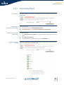
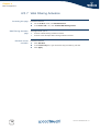
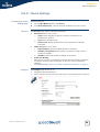
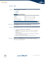
You can add a wireless client to the ACL as follows:
1
Go to the SpeedTouch™ web pages.
2
In the menu select Home Network > Devices.
3
Under Pick a task..., click Search for wireless devices.
4
The SpeedTouch™ searches for new wireless stations that use the encryption
key of the SpeedTouch™ Access Point.
5
The SpeedTouch™ takes you to the Home Network. The new station will be
shown next to the name of the SpeedTouch™ WLAN.
6
Click the name of the new station.
7
Click Configure.
8
Select Allowed on WLAN and click Apply.
9
Now the device is added to the ACL and will always be allowed to connect to
the SpeedTouch™.
29
Chapter 2
Local Network Setup
Registering clients via
association button
You can easily register new wireless network clients as follows:
1
Push the Association button on the SpeedTouch™ back panel for at least two
seconds. The WLAN LED will toggle between green and red.
The ACL will be unlocked for a time frame of one minute. Any new wireless
client successfully attempting to connect to the SpeedTouch™ (having the
correct wireless settings, that is the network name and, if required, the
network key) within the time frame of one minute, will be added to the table.
The SpeedTouch™ automatically saves your current configuration at the end of
the registration phase.
Some WLAN clients do not automatically join a WLAN. If so, follow
the instructions for the WLAN client software to initiate the
association.
2
Successfully registered stations are associated to the SpeedTouch™ WLAN.
Depending on your WLAN client adapter, a wireless icon may become green or
a message similar to the following may appear: “Successfully joined Wireless
network SpeedTouch123456”.
3
The wireless clients will be added to the SpeedTouch™ ACL.
4
After one minute the ACL is locked.
The registration procedure can be repeated as often as needed.
30
E-DOC-CTC-20050429-0104 v1.0
Chapter 2
Local Network Setup
2.2.5 Extending the Range of Your Wireless Network
WDS
The SpeedTouch™ features Wireless Distribution System (WDS) functionality. This
feature allows you to extend the range of your wireless network by introducing one
or more WDS-enabled devices into your wireless network.
The Wireless Distribution System (WDS) enables data packets to pass from one
wireless access point to another, just as if the access points were ports on a wired
Ethernet switch. WDS allows you to extend the range of your SpeedTouch™ by
means of one or more wireless repeaters, like for instance a SpeedTouch™180. The
following illustration depicts two WDS-enabled devices communicating via WDS:
WDS Link
SpeedTouch™180
SpeedTouch™620
The SpeedTouch™ allows you to add up to four wireless repeaters.
Repeaters extend the coverage area of your wireless LAN, however bear in
mind that throughput is reduced for wireless clients that are connected
through a repeater.
Preconditions
Check on following:
Your wireless repeater must be WDS enabled.
Both your SpeedTouch™ and your wireless repeater must use:
The same WEP key if WEP is enabled.
!
WPA encryption is not supported when using WDS.
The same fixed channel.
The SpeedTouch™ and your wireless repeater do not necessarily need to use
the same SSID. Using different SSIDs allows you to force your wireless
clients to use either the access point of the SpeedTouch™ or the one of your
wireless repeater.
E-DOC-CTC-20050429-0104 v1.0
31
Chapter 2
Local Network Setup
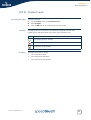
Configuring WDS
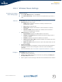
To configure your WDS on the web pages:
1
Go to the SpeedTouch™ web pages.
2
In the menu select Home Network.
3
Click your WLAN.
4
On the top right, click Configure.
If not already done, set a fixed channel and check whether the security
settings (WEP encryption or no encryption) on your SpeedTouch™ are
the same as on the repeater.
5
On the Wireless Access Point page, in the Pick a task... list, click Configure
WDS.
6
Select WDS Enabled.
7
In the Pick a task... list, click Scan for wireless access points.
8
A warning will be displayed:.
Click OK.
9
The SpeedTouch™ will scan for access points on the same radio channel.
10 Select your repeater in the List of Accessible Access Points and click Apply.
32
E-DOC-CTC-20050429-0104 v1.0
Chapter 3
Internet Connectivity Dial-In Clients
3 Internet Connectivity Dial-In Clients
Introduction
Access methods
For setting up initial Internet connectivity, using the Home Install Wizard on the
Setup CD or the embedded Easy Setup, refer to the provided Installation and Setup
Guide.
Depending on the configuration of the SpeedTouch™ you may have:
Direct access:
As soon as the initial configuration has been done, immediate and uninterrupted
WAN access is provided.
In case of direct access, the remote organisation might ask for a user
name and password on an Internet welcome page.
Dial-in access:
Access must be explicitly established, that is by “dialling” into a Broadband
Remote Access Server (BRAS).
Depending on the SpeedTouch™ configuration, dial-in access is provided via the
SpeedTouch™’s Routed PPPoA or Routed PPPoE packet services with
embedded PPP client.
Connection protocols
The applied connection protocol model depends on the service profile you selected to
configure the SpeedTouch™ and should correspond with the Service Provider’s
requirements. If your ISP provides PPPoE for instance, you should configure PPPoE.
More information on connection protocols can be found in the Internet Connection
Configuration Guide.
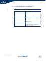
Dial-in clients
There are different ways of dialling in, depending on the operating system on your PC
and your preferences.
can be used on
following operating
system:
For more information,
see:
Dial-in client on
embedded pages
MS Windows, Mac, unix,
other
“3.1 SpeedTouch™ Web
Pages”
MS Windows XP IGD
Control Agent for UPnP
MS Windows XP
“3.2 IGD Control Agent”
on page 37
Dial-in method:
Embedded PPP dial-in client:
Host PPP dial-in client for a SpeedTouch™ configured in pure bridging mode:
E-DOC-CTC-20050429-0104 v1.0
MS Windows XP
Broadband connection
MS Windows XP
“3.3 MS Windows XP
BroadBand Connection”
Mac OS X PPPoE dial-in
client
Mac OS X
“3.4 Mac OS X PPPoE
Dial-in Client”
33
Chapter 3
Internet Connectivity Dial-In Clients
Embedded PPP dial-in
clients
The SpeedTouch™’s embedded PPP dial-in client allows you to establish an Internet
connection for computers residing on your local network, using only one computer of
the network to control the client.
If this computer runs:
Broadband host PPPoE
dial-in clients
Any Operating System
you can always use the SpeedTouch™ web pages.
See “3.1 SpeedTouch™ Web Pages” on page 35 to proceed.
MS Windows XP
you can use MS Windows XP’s Internet Gateway Device Control Client.
See “3.2 IGD Control Agent” on page 37 to proceed.
You can also connect to the Internet using a Broadband PPPoE dial-in application.
The PPP over Ethernet connection scenario provides PPP-like dial-in behaviour over
the virtual Ethernet segment.
To be able to use a broadband dial-in application on your computer for connecting to
the Internet, the SpeedTouch™ needs to be configured for Bridged Ethernet or Routed
PPPoE (with PPPoE relay) via the SpeedTouch™ Home Install Wizard on the Setup CD
or the embedded Easy Setup.
If this computer runs:
MS Windows XP
you can use the MS Windows XP broadband dial-in client. See “3.3 MS
Windows XP BroadBand Connection” on page 39 for more information.
Mac OS X
you can use a Mac OS X broadband dial-in client. See “3.4 Mac OS X PPPoE
Dial-in Client” on page 43 for more information.
- or -
A broadband PPPoE dial-in client provided by your Service Provider to connect
to the Internet
Upon availability of OS-specific PPPoE dial-in client applications, the
latter method is Operating System independent.
For PPPoE session connectivity from a Mac OS 8.6/9.x, an MS
Windows 95/98(SE)/ME/2000 or a Linux system, a host PPPoE dial-in
application is mandatory.
34
E-DOC-CTC-20050429-0104 v1.0
Chapter 3
Internet Connectivity Dial-In Clients
3.1 SpeedTouch™ Web Pages
Introduction
As the SpeedTouch™ web pages are controllable from any Operating System with an
installed web browser, the method to establish PPP sessions described below you
can use on any computer system.
For more information on Internet connection setup, see the provided Installation and
Setup Guide.
Starting an Internet
session
Proceed as follows:
1
Open a web browser on your computer and browse to the SpeedTouch™ web
pages (see “1.3.1 Access via the Web Interface” on page 12 for more
information):
By default the SpeedTouch™ shows you the Home page.
2
Click Connect at the appropriate broadband connection.
You might be requested to enter your user name and password.
As a result SpeedTouch™’s embedded PPP dial-in client establishes the Internet
connection.
3
Monitoring your
Internet connection
E-DOC-CTC-20050429-0104 v1.0
Now you can surf the Internet.
You are able to overview and monitor your Internet connectivity as long as the
session is running via:
The SpeedTouch™ System Information page: see “4.3.1 Information” on
page 54.
The SpeedTouch™ Diagnostics task: see “4.4.1 Connectivity Check” on
page 63.
35
Chapter 3
Internet Connectivity Dial-In Clients
Terminating an Internet
session
To close an active PPP connection:
1
Go to the SpeedTouch™ Home page.
2
Click Disconnect at the appropriate broadband connection.
As a result the SpeedTouch™’s embedded PPP dial-in client will close the Internet
connection. The Internet Link status will change to Disconnected and your PC is offline.
36
E-DOC-CTC-20050429-0104 v1.0
Chapter 3
Internet Connectivity Dial-In Clients
3.2 IGD Control Agent
Introduction
MS Windows XP users can easily establish PPP sessions, thanks to MS Windows
XP’s Internet Gateway Device (IGD) Discovery and Control Client that allows you to
control the SpeedTouch™ directly from you PC.
The IGD control client only allows to connect or to disconnect a fully
configured connection.
Preconditions
Following conditions must be met:
Starting an Internet
session
Following subcomponents of Windows XP’s Networking Services must be
added to your Windows XP system:
UPnP™ (see “ SpeedTouch™ not detected by UPnP™ or IGD Control Client”
on page 197).
IGD Discovery and Control Client (see “ Adding IGD Discovery and
Control” on page 198).
UPnP™ must be enabled on your SpeedTouch™. To enable UPnP, see
“4.5.2 Game & Application Sharing” on page 69.
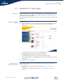
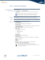
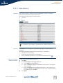
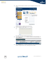
Proceed as follows:
1
In the Windows task bar, click Start.
2
Select (Settings >) Control Panel.
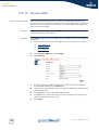
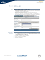
3
The Control Panel window appears. Go to (Network and Internet Connections
>) Network Connections.
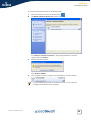
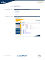
4
The Network Connections window appears:
You will find an Internet Gateway icon, representing the SpeedTouch™ IGD
Internet connection ability.
5
Double-click the Internet Connection icon.
As a result the SpeedTouch™’s embedded PPP dial-in client establishes the
Internet connection. The Internet Gateway icon displays connected and your
PC is online.
6
E-DOC-CTC-20050429-0104 v1.0
You can open a web browser and surf the Internet.
37
Chapter 3
Internet Connectivity Dial-In Clients
Internet connection
status
Terminating an Internet
session
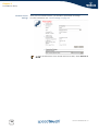
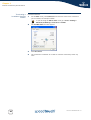
As long as the SpeedTouch™’s embedded PPP dial-in client is connected, you are able
to overview the connection status and some counters by double-clicking the Internet
Connection icon in your PC’s Network Connections window:
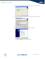
Proceed as follows:
1
In the Windows task bar, click Start.
2
Select (Settings >) Control Panel > (Network and Internet Connections >)
Network Connections.
3
In the Network Connections window, right-click the Internet Connection icon
and select Disconnect to close the session.
You can also double-click the icon. Then the Internet Connection
Status window will appear on which a Disconnect button is available
to close the session.
4
38
As a result the SpeedTouch™’s embedded PPP dial-in client will close the
Internet connection. The Internet Gateway icon displays Disconnected and
your computers are off-line.
E-DOC-CTC-20050429-0104 v1.0
Chapter 3
Internet Connectivity Dial-In Clients
3.3 MS Windows XP BroadBand Connection
Prerequisites
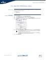
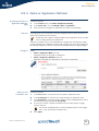
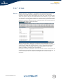
Configuring a
broadband connection
To be able to use the MS Windows XP BroadBand Connection, your SpeedTouch™
must be configured for either:
Bridging, or
PPPoE Relay
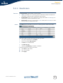
Proceed as follows:
1
On the Start menu, click (Settings >) Control Panel.
2
The Control Panel window appears. Go to (Network and Internet Connections
>) Network Connections.
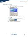
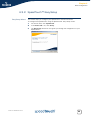
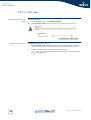
3
In the Network Tasks menu, click Create a new connection.
The New Connection Wizard appears:
Click Next.
E-DOC-CTC-20050429-0104 v1.0
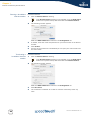
4
Select Connect to the Internet and click Next.
5
Select Set up my connection manually and click Next.
6
Select Connect using a broadband connection that requires a user name and
password and click Next.
7
Give a name to the connection you are creating, for example YourISP:
39
Chapter 3
Internet Connectivity Dial-In Clients
8
Select whether the connection will be available to any user or only to yourself:
9
Fill in the Internet account information. This information should be provided by
your service provider:
10 At the end of the configuration the following window appears:
Click Finish to complete the configuration.
The Connect YourISP window (see below) appears.
40
E-DOC-CTC-20050429-0104 v1.0
Chapter 3
Internet Connectivity Dial-In Clients
Starting a broadband
Internet session
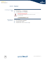
Proceed as follows:
1
On the Start menu, point Connect To and click the name of the connection
you’ve created, for example YourISP.
If you are using the Classic Start menu click Start > Settings >
Network (and Dial-up) connections > YourISP.
E-DOC-CTC-20050429-0104 v1.0
2
The Connect YourISP window appears:
3
If requested, enter user name and password for your user account at the
Service Provider.
4
Click Connect.
5
As soon as the connection is established, the Connection message box and
Dialup window are minimised into an icon in the notification area:
6
You can open your web browser and surf the Internet.
41
Chapter 3
Internet Connectivity Dial-In Clients
Terminating a
broadband Internet
session
Proceed as follows:
1
On the Start menu, point Connect To and click the name of the connection
you’ve created, for example YourISP.
If you are using the Classic Start menu go to Start > Settings >
Network (and Dial-up) connections > YourISP.
42
2
The YourISP Status window appears:
3
Click Disconnect.
4
The connection is released. As a result no Internet connectivity exists any
more.
E-DOC-CTC-20050429-0104 v1.0
Chapter 3
Internet Connectivity Dial-In Clients
3.4 Mac OS X PPPoE Dial-in Client
Prerequisites
Configuring a
broadband connection
To be able to use the MS Windows XP BroadBand Connection, your SpeedTouch™
must be configured for either:
Bridging, or
PPPoE Relay
Proceed as follows:
1
On the Apple menu, click System Preferences.
2
In the System Preferences window, click the Network icon.
3
The Network window appears. Make sure Built-in Ethernet is selected in the
Show list and click the PPPoE tab:
4
Enter the Account Name and Password provided by your Service Provider.
Select Save password in case you want the computer to remember
the password for this account name.
Optionally you can enter a name for this connection in the Service
Provider field. All other fields may stay empty.
5
E-DOC-CTC-20050429-0104 v1.0
Click Apply Now.
43
Chapter 3
Internet Connectivity Dial-In Clients
Starting a broadband
Internet session
Proceed as follows:
1
Click the Internet Connect dockling.
If the Internet Connect dockling is not available, go to the Applications
folder on the system startup disk and double-click Internet Connect.
2
The following window appears:
Make sure Built-in Ethernet is selected in the Configuration list.
Terminating a
broadband Internet
session
3
If needed, enter user name and password for your user account at the Service
Provider.
4
Click Connect.
5
As soon as the connection is established you can open your web browser and
surf the Internet.
Proceed as follows:
1
Click the Internet Connect dockling.
If the Internet Connect dockling is not available, go to the Applications
folder on the system startup disk and double-click Internet Connect.
2
The following window appears:
Make sure Built-in Ethernet is selected in the Configuration list
44
3
Click Disconnect.
4
The connection is released. As a result no Internet connectivity exists any
more.
E-DOC-CTC-20050429-0104 v1.0
Chapter 4
Basic Configuration
4 Basic Configuration
Introduction
The SpeedTouch™ comes with embedded HTML pages, providing an interface to the
software installed on the device. It allows easy setup and management of the
SpeedTouch™ via your web browser form any PC connected to the SpeedTouch™.
See “1.3.1 Access via the Web Interface” on page 12 to access the pages.
Basic and Expert Mode
SpeedTouch™
documentation
E-DOC-CTC-20050429-0104 v1.0
The pages are grouped in:
Basic Mode: offering the main configuration tasks
Expert Mode: adding advanced features to the basic mode and presenting the
Command Line Interface (CLI) commands in a graphical user interface.
Consult:
The SpeedTouch™ Installation and Setup Guide
for more information on setup and installation procedures.
The SpeedTouch™ Application Notes and Configuration guides
for advanced configuration concepts.
45
Chapter 4
Basic Configuration
4.1 Navigation
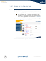
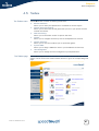
Navigation components
The SpeedTouch™ web interface consists of following components:
Menu
Language Bar
Navigation Bar
Notification Area
Tasks
Navigation bar
Notification area
Language bar
Menu
Tasks
46
E-DOC-CTC-20050429-0104 v1.0
Chapter 4
Basic Configuration
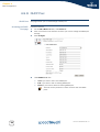
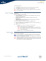
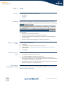
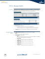
4.1.1 Menu
Menu items
Collapsing and
expanding the menu
E-DOC-CTC-20050429-0104 v1.0
The menu is located on the left side of the page and consists of the following menu
items:
SpeedTouch:
Provides basic information on the SpeedTouch™.
Broadband Connection:
Allows you to view/configure your broadband connections.
Toolbox:
Allows you to assign games or applications to a device and secure your
Internet connection.
Office Network:
Allows you to manage your local network.
Expert Configuration Mode:
Allows you to go to Expert Configuration mode for advanced configuration and
maintenance of your SpeedTouch™ device.
You are able to collapse/expand the menu by clicking the arrow located on the top
of the menu.
47
Chapter 4
Basic Configuration
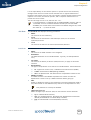
4.1.2 Language Bar
Language bar
The language bar is located under the SpeedTouch™ logo and allows you to change
the language of the SpeedTouch™ web interface.
!
48
The language bar will only be shown if more than one language is available.
E-DOC-CTC-20050429-0104 v1.0
Chapter 4
Basic Configuration
4.1.3 Navigation Bar
Navigation bar
Display level
E-DOC-CTC-20050429-0104 v1.0
The navigation bar is located on the top of the page and allows you to:
View the current user name.
Click this name to change your password or switch to another user.
View the current position on the SpeedTouch™ web interface.
Get context related Help information.
Depending on the page you are viewing following buttons will be available:
Overview to view a summary of the current status or configuration.
Details to view more detailed information on the current status or
configuration.
Configure to change the current settings.
49
Chapter 4
Basic Configuration
4.1.4 Notification Area
Notification area
The notification area is located under the Navigation Bar and is used to display:
Error messages indicated by a red traffic light.
Warnings indicated by an orange traffic light.
Information indicated by a green traffic light.
If none of these events occur, the notification area will not be shown.
50
E-DOC-CTC-20050429-0104 v1.0
Chapter 4
Basic Configuration
4.1.5 Tasks
Tasks
E-DOC-CTC-20050429-0104 v1.0
To allow a swift configuration of your SpeedTouch™, some pages may offer you a
number of related tasks. These tasks will guide you to the page where you can
perform the selected task.
51
Chapter 4
Basic Configuration
4.2 Home
SpeedTouch™ home
page
52
The SpeedTouch™ home page gives you a short overview of all the configurable
aspects of the SpeedTouch™:
SpeedTouch
Broadband Connection
Toolbox
Office Network
E-DOC-CTC-20050429-0104 v1.0
Chapter 4
Basic Configuration
4.3 SpeedTouch
The SpeedTouch menu
The SpeedTouch page
E-DOC-CTC-20050429-0104 v1.0
The SpeedTouch menu consists of following items:
Information
Configuration
Event Logs
Update
The SpeedTouch page gives you some basic information on the SpeedTouch™:
Product Information
Configuration
53
Chapter 4
Basic Configuration
4.3.1 Information
Information
54
The Information page summarizes important information on your SpeedTouch™. You
may need this information when you contact your helpdesk.
E-DOC-CTC-20050429-0104 v1.0
Chapter 4
Basic Configuration
4.3.2 SpeedTouch™ Easy Setup
Easy Setup Wizard
This wizard helps you configure your SpeedTouch™ Internet connection.
To configure the SpeedTouch™ using the SpeedTouch™ Easy Setup wizard:
E-DOC-CTC-20050429-0104 v1.0
1
On the left menu, click SpeedTouch.
2
In the Pick a task... list, click Set up.
3
The Easy Setup wizard will now guide you through the configuration of your
SpeedTouch™.
55
Chapter 4
Basic Configuration
4.3.3 Restart
Accessing the Restart
page
Restarting your
SpeedTouch™
56
Proceed as follows:
1
On the left menu, click SpeedTouch.
2
In the Pick a task... list, click Restart.
Proceed as follows:
1
Click Yes, restart my SpeedTouch.
2
The SpeedTouch™ restarts.
3
The SpeedTouch™ returns to the Home page.
E-DOC-CTC-20050429-0104 v1.0
Chapter 4
Basic Configuration
4.3.4 Configuration
Overview
Details
Configure
The Overview page displays the current configuration of your SpeedTouch™.
The Details page displays more detailed information on the current configuration of
your SpeedTouch™.
The Configure page allows you to change the current configuration.
If you want to:
Reconfigure your SpeedTouch™:
Click Configuration Wizard under Service Configuration. For more information,
see “4.3.2 SpeedTouch™ Easy Setup” on page 55.
Configure the time settings of your SpeedTouch™:
Select Auto-configuration if you want the SpeedTouch™ to use a time
server to synchronise its clock to a dedicated time server.
Clear Auto-configuration to manually configure the SpeedTouch™ time
settings.
Disable/enable web browsing interception or set it to automatic.
!
If you disable web browsing interception or set it to automatic you will
not be able to use Web Site Filtering.
Click Apply to save your settings.
E-DOC-CTC-20050429-0104 v1.0
57
Chapter 4
Basic Configuration
4.3.5 Backup & Restore
Introduction
Accessing the Backup
& Restore page
Saving your current
configuration
Restoring a previously
saved configuration
58
This page allows you to:
Save your current configuration.
Restore a previously saved configuration.
Proceed as follows:
1
On the SpeedTouch menu, click Configuration.
2
Click Configure.
3
In the Pick a task... list, click Save or Restore Configuration.
Proceed as follows:
1
Click Backup Configuration Now.
2
Click Save.
3
Choose a location to save your backup file and click Save.
Proceed as follows:
1
Click Browse.
2
Select the configuration file you want to restore and click Open.
3
Click Restore Configuration Now....
4
The SpeedTouch™ loads your configuration and restarts.
5
At the end of the procedure, the SpeedTouch™ returns to the Home page.
E-DOC-CTC-20050429-0104 v1.0
Chapter 4
Basic Configuration
4.3.6 Reset to Factory Defaults
Introduction
Accessing the Reset to
Factory Defaults page
Resetting the
SpeedTouch™ to
factory defaults
E-DOC-CTC-20050429-0104 v1.0
This page allows you to reset the SpeedTouch™ to return to the initial configuration
of your SpeedTouch™. All your changes will be deleted.
Proceed as follows:
1
On the left menu, click SpeedTouch.
2
In the Pick a task... list, click Return to Factory Default Settings.
If you want to reset your SpeedTouch™ to factory defaults, click Yes, reset my
SpeedTouch.
!
If you reset your SpeedTouch™ to factory default settings, all active
connections will be disconnected.
59
Chapter 4
Basic Configuration
4.3.7 Event Logs
Event Logging
The Event Logs page summarizes the latest events recorded on your SpeedTouch™.
Recorded Events table
The Recorded Events table gives you an overview of the latest event logs that have
been recorded since power on. The first column of the table indicates the importance
of the event log
Indicator
Description
Informational
Warning
Error
The Category list allows you to filter the events shown in the Recorded Events
table. For example, by clicking Security you can view all security related events, for
example generated by the SpeedTouch™ firewall.
60
E-DOC-CTC-20050429-0104 v1.0
Chapter 4
Basic Configuration
4.3.8 Update
Updating the
SpeedTouch™ system
software
E-DOC-CTC-20050429-0104 v1.0
The Update page allows you to:
View System Information.
View information on the current System Firmware.
Update your SpeedTouch™ from a remote server.
Use this option if you want to have yourSpeedTouch™ check on the internet for
new firmware and update if it found one.
Update from a PC.
Use this option if you want to install on your SpeedTouch™ that is located on
the PC.
61
Chapter 4
Basic Configuration
4.4 Broadband Connection
The Broadband
Connection menu
The Broadband
Connection page
The Broadband Connection menu consists of following menu items:
DSL Connection
Internet Services
The Broadband Connection page gives you a short status overview of the
connections configured on the SpeedTouch™.
Click View more to see more information on the selected broadband connection.
If you configured a dial-up connection, you are able to establish/terminate
the connection by clicking Connect/Disconnect.
62
E-DOC-CTC-20050429-0104 v1.0
Chapter 4
Basic Configuration
4.4.1 Connectivity Check
Introduction
Accessing the
Connectivity Check page
Checking you Internet
Connectivity
Analysing the test
results
E-DOC-CTC-20050429-0104 v1.0
This page enables you to perform a connectivity check on an Internet service of your
SpeedTouch™.
Proceed as follows:
1
On the left menu, click Broadband Connection.
2
In the Pick a task... list, click Check connectivity to the Internet.
Proceed as follows:
1
In the Internet Service to Check list, click the Internet service that you want to
check.
2
Click Check Connectivity.
3
The SpeedTouch™ lists the test results in the Test Results list.
If the test is successful, you will get a list of green check marks. Otherwise a red
cross will indicate which tests have failed.
63
Chapter 4
Basic Configuration
4.4.2 DSL Connection
Overview
Details
64
Click Overview to view brief information on your DSL connection.
Click Details to view a more detailed information on your DSL connection.
E-DOC-CTC-20050429-0104 v1.0
Chapter 4
Basic Configuration
4.4.3 Internet Services
Internet Services
information
The Internet Services page displays information on your Internet Connection(s).
If you configured a dial-up connection you are able to establish/terminate
the connection by clicking Connect/Disconnect.
To view more detailed information on a specific connection, click the View more...
link of the corresponding connection.
E-DOC-CTC-20050429-0104 v1.0
65
Chapter 4
Basic Configuration
4.4.4 Internet Service Settings
Accessing the Internet
Service Settings page
Overview
Proceed as follows:
1
On the Broadband Connection menu click Internet Services.
2
Click the View more link of the internet service you want to view.
The Overview page gives you basic information on the selected Internet Service.
If you configured a connection you are able to establish/terminate the
connection by clicking Connect/Disconnect.
Details
The Details page gives you more detailed information on the selected Internet
Service.
If you configured a dial-up connection you are able to establish/terminate
the connection by clicking Connect/Disconnect.
66
E-DOC-CTC-20050429-0104 v1.0
Chapter 4
Basic Configuration
4.5 Toolbox
The Toolbox menu
The Toolbox page
E-DOC-CTC-20050429-0104 v1.0
The Toolbox menu consists of following menu items:
Remote Assistance:
Allows you to make your SpeedTouch™ accessible for remote support.
Game & Application Sharing:
Allows you to share services and games that you run in your private network
towards the internet.
Web Site Filtering:
Allows you to block/allow access to specific web sites.
Firewall:
Allows you to configure the security level of the SpeedTouch™ firewall.
Intrusion Detection:
Allows you to view the intrusions you are protected against.
Dynamic DNS:
Allows you to assign a DNS host name to your broadband connection(s).
User Management:
Allows you to manage the users configured on your SpeedTouch™.
The Toolbox page gives you an overview of the available services and their current
status. You can click on the names of these services to go to the corresponding web
page.
67
Chapter 4
Basic Configuration
4.5.1 Remote Assistance
Enabling Remote
Assistance
This page allows you to make your SpeedTouch™ accessible for remote support.
You must be connected to the Internet to be able to enable remote
assistance.
!
To use remote assistance:
1
If needed, type a password in the Password box.
2
Click Enable Remote Assistance.
3
Pass the information listed under:
URL
Username
Password
to your technical support, in order for them to be able to access your
SpeedTouch™.
Once the technical support is connected, no other connections are
possible.
4
68
The remote assistance session ends:
If the technical support disables remote assistance.
After 20 minutes of inactivity, or after a reboot, remote management.
E-DOC-CTC-20050429-0104 v1.0
Chapter 4
Basic Configuration
4.5.2 Game & Application Sharing
Overview
Configure
The Overview page summarizes the games and applications on a particular host on
your network, for which the SpeedTouch™ accepts connections coming from the
Internet.
The Configuration page allows you to:
Select Use UPnP to enable UPnP on the SpeedTouch™.
Universal Plug and Play is an architecture for transparent peer-to-peer
connectivity of PCs, intelligent appliances, and (wireless) devices. It
enables seamless operation of a wide range of games and messaging
applications.
E-DOC-CTC-20050429-0104 v1.0
Select Use Extended Security to only allow the creation of port maps.
Assign a game or application to a specific network device.
69
Chapter 4
Basic Configuration
4.5.3 Defined Games & Applications
Accessing the Defined
Games & Applications
page
Proceed as follows:
The Defined Games &
Applications page
This page gives you an overview of the games and applications defined on your
SpeedTouch™. Each game or application can be assigned to a device on your local
network.
1
In the Toolbox menu, click Game & Application Sharing.
2
In the Pick a task... list, click Modify a game or application.
To:
70
View the translation rules of a game or application, click the name of the rule.
Change the translation rules of a game or application, click the Edit link of the
the game or application.
E-DOC-CTC-20050429-0104 v1.0
Chapter 4
Basic Configuration
4.5.4 Game or Application Definition
Accessing the Game or
Application Definition
page
Overview
Proceed as follows:
1
In the Toolbox menu, click Game & Application Sharing.
2
In the Pick a task... list, click Modify a game or application.
3
Click the name of the game or application you want to view/change.
This page gives you an overview of the port mappings used to allow this service or
game to be initiated from the Internet.
Consult the user’s guide or support pages of your application to know which
ports are being used by this application.
A service is made of one or more TCP/UDP port ranges. Each incoming port range
can be translated into a different internal (local network) port range. Port ranges can
be statically assigned to devices or dynamically assigned using an outgoing trigger.
Configure
Adding a Port
Translation rule
Under:
Game or Application Name you can:
Change the name of the game or application.
Game or Application Definition you can:
Change the TCP/UDP port definition for this game or application.
Proceed as follows:
1
In the Protocol list, click the protocol the game or application uses.
2
In the Port Range box, type the port range the game or application uses.
3
In the Translate To... box, type the port range to which the SpeedTouch™ has to
translate the ports specified under Port Range.
4
If you want to make a dynamic translation rule you must specify a trigger
protocol and port.
As soon as the SpeedTouch™ receives outgoing traffic on this trigger
port, it will activate this translation rule.
5
E-DOC-CTC-20050429-0104 v1.0
Click Apply.
71
Chapter 4
Basic Configuration
4.5.5 New Game or Application
Accessing the Game or
Application Definition
Creating a new game or
application
72
Proceed as follows:
1
On the Applications page, click Game & Application Sharing.
2
In the Pick a task... list, click Create a new game or application.
Proceed as follows:
1
Type the name of the game or application in the Name box.
2
Click:
Clone Existing Game or Application if you want to start from the port
mappings of the selected game or application.
Manual Entry of Port Maps if you want to manually configure the port
mapping for this game or application.
3
The SpeedTouch™ creates the game or application and takes you to the Game
or Application Definition page to configure the port mappings for this game or
application.
4
Enter the necessary port mappings and click Add.
E-DOC-CTC-20050429-0104 v1.0
Chapter 4
Basic Configuration
4.5.6 Web Site Filtering
Web Site Filtering
The SpeedTouch™ allows you to block/allow particular web sites:
Based on the web site’s URL.
As within a web site lots of references can be made to other URLs, it is
recommended to use this feature in combination with content based
filtering.
Based on the web site’s content.
Redirect a web site to another web site.
If your administrator account is configured as default user, make sure to
configure a password for this account or change the default user. Otherwise
users on your local network can surf to your SpeedTouch™ to disable your
filtering rules.
!
For more information, see “4.5.13 User Management” on page 83 and
“4.5.15 Change Default User” on page 85.
Overview
The Overview page displays:
The current Address Based Filtering rules.
The current Content Based Filtering configuration.
To view which content types are blocked/allowed, click Details. For more
information, see “4.5.8 Content Level” on page 77.
!
Configure
Content levels
E-DOC-CTC-20050429-0104 v1.0
Address based filtering rules have priority over content based filtering
rules.
The Configure page allows you to:
Deny access to a specific web site.
Allow access to a specific web site.
Redirect a web site.
Configure content based filtering settings.
Following content levels are available:
All:
Allow all categorized web sites.
Legal:
Allow all except illegal, extreme, spam and spyware web sites.
Teenagers:
Block illegal, adult, extreme, online ordering/gambling, spam and spyware web
sites.
Children:
Only allow children-save web sites.
BlockAll:
Block all categorized web sites.
73
Chapter 4
Basic Configuration
Deny access to a
specific web site
Use this feature if:
Allow is selected under Action for Unknown Sites.
Block is selected under Action for Unknown Sites and you want to make an
exception on an allow rule. For example: you are allowing “provider.com” but
you want to deny access to “mail.provider.com”.
A content category/group is allowed by Content Based Filtering and you want
to make an exception. For example: you are allowing Web Mail content but you
want to deny access to “mail.provider.com”.
Proceed as follows:
1
Type the URL of the web site you want to block (for example
“mail.provider.com”) in the Web Site box.
2
In the Action list, click:
3
Allow access to a
specific web site
Block if you want to block this web site.
Redirect if you want to redirect to another page. Type the address of the
redirect page in the Redirect box.
Click Add.
Use this feature if:
Block is selected under Action for Unknown Sites
Allow is selected under Action for Unknown Sites and you want to make an
exception on a block/redirect rule. For example: you are blocking “bank.com”
but you want to allow access to “netbanking.bank.com”.
A content category/group is blocked by Content Based Filtering and you want
to make an exception. For example: you are blocking Finance / Investment
content but you want to allow access to “netbanking.bank.com”.
Proceed as follows:
Redirect a web site
74
1
Type the URL of the web site you want to allow (for example
“netbanking.bank.com”) in the Web Site box.
2
Click Allow in the Action list.
3
Click Add.
Proceed as follows:
1
Type the URL of the web site you want to redirect (for example “cracks.am”) in
the Web Site box.
2
Click Redirect in the Action list.
3
Type the URL of the web site you want to redirect to (for example
“mycompany.com/internetpolicy.htm”) in the Redirect box.
4
Click Add.
E-DOC-CTC-20050429-0104 v1.0
Chapter 4
Basic Configuration
Redirecting all web
sites
Configure content
based filtering settings
Proceed as follows:
1
Type “*” in the Web Site box.
2
Click Redirect in the Action list.
3
Type the URL of the web site you want to redirect to (for example
“mycompany.com/internetpolicy.htm”) in the Redirect box.
4
Click Add.
5
Type the URL of the web site you want to redirect to (for example
“mycompany.com/internetpolicy.htm”) in the Web Site box.
6
Click Allow in the Action list.
7
Click Add.
Under Content Based Filtering you are able to:
Enable/disable content based filtering.
Allow/block uncategorized web sites.
Select a content level in the Content Level list.
To change a content level definition, click the Edit link of the content
level you want to change. For more information, see “4.5.8 Content
Level” on page 77.
E-DOC-CTC-20050429-0104 v1.0
75
Chapter 4
Basic Configuration
4.5.7 Web Filtering Activation
Accessing this page
Web Filtering Activation
page
Standard license
activation
76
Proceed as follows:
1
On the Toolbox menu, click Parental Control.
2
In the Pick a task... list, click Activate Web filtering License.
This page allows you to:
Activate a Web Filtering evaluation license.
Activate a free 30-days Web Filtering evaluation license.
Proceed as follows:
1
Click Standard.
2
In the License Key box, type the license key provided by your ISP.
3
Click Apply.
E-DOC-CTC-20050429-0104 v1.0
Chapter 4
Basic Configuration
4.5.8 Content Level
Accessing this page
Overview
Proceed as follows:
1
On the Toolbox menu, click Parental Control.
2
Click Configure.
3
Click the Edit link of the content level you want to edit.
This page gives you an overview of the different categories and their rules.
Following icons indicate whether the content type is allowed or not:
Icon
Description
The category/group is allowed
The category/group is not allowed.
The group is partly allowed.
Configure
E-DOC-CTC-20050429-0104 v1.0
This page allows you to change:
The content level name.
The content level description.
The content level configuration.
77
Chapter 4
Basic Configuration
4.5.9 New Content Level
Introduction
Procedure
This page allows you to create a new content level. To access this page:
1
On the Toolbox menu, click Parental Control.
2
In the upper right corner, click Configure.
3
Under Pick a task..., click Create a new content level.
To apply a new content level following actions must be performed:
1
Content level creation
2
Content level configuration
3
Content level definition
4
Content level activation
!
Content level creation
Content level
configuration
You can create up to 16 content levels.
Proceed as follows:
1
In the Name box, type a name for the new content level.
2
In the Description box, type a short text to describe what this security level will
do.
3
Click Next.
Proceed as follows:
1
The Configuration section becomes available.
2
Click:
Clone Existing Level to start from a previously created content level.
If no levels have been defined before, this option will not be
shown.
3
Content level definition
Black List to allow all web sites by default.
White List to block all web sites by default.
Click Next.
Only web sites that match the selected content level will be allowed. Proceed as
follows:
1
2
78
If you want to:
Allow a category:
Select the check box next to the category name.
Allow an entire group:
Select the check box next to the group name.
Block a category:
Clear the check box next to the category name.
Block an entire group:
Clear the check box next to the group name.
Click Apply.
E-DOC-CTC-20050429-0104 v1.0
Chapter 4
Basic Configuration
Content level activation
E-DOC-CTC-20050429-0104 v1.0
To activate your new content level:
1
On the Toolbox menu, click Parental Control.
2
In the upper right corner, click Configure.
3
In the Content Level list, select your new content level.
4
The new content level is now active.
79
Chapter 4
Basic Configuration
4.5.10 Firewall
Overview
Configure
The Overview page summarizes the overall security policy configured on your
SpeedTouch™.
The Configure page allows you to select the security level of the SpeedTouch™.
Select one of following security levels:
80
Medium:
Use this Security Level to allow all outgoing connections except Windows
protocols (Netbios, RPC, SMB) and block all incoming connections. Game and
Application sharing is allowed by the firewall.
Standard:
Use this Security Level to allow all outgoing connections and block all incoming
traffic. Game and Application sharing is allowed by the firewall.
Low:
Use this Security Level to allow all outgoing connections and block all incoming
traffic except Internet Control Management Protocol (ICMP). Game and
Application sharing is allowed by the firewall.
Disabled:
All traffic is allowed to pass through your SpeedTouch™. Game and Application
sharing is allowed by the firewall.
BlockAll:
Use this Security Level to block all traffic from and to the Internet. Game and
Application sharing is not allowed by the firewall.
E-DOC-CTC-20050429-0104 v1.0
Chapter 4
Basic Configuration
4.5.11 Intrusion Detection
Intrusion Detection
Your SpeedTouch™ is protecting your network against malicious intrusions. This page
shows you the intrusions you are protected against.
The Protected Intrusions table shows the number of times the SpeedTouch™ actively
protected your network against each intrusion since last statistics reset.
E-DOC-CTC-20050429-0104 v1.0
81
Chapter 4
Basic Configuration
4.5.12 Dynamic DNS
What is Dynamic DNS
Overview
Configure
The Dynamic DNS service allows you to assign a dynamic DNS host name (e.g.
john.dyndns.org) to a broadband connection even if it is using a dynamic IP address.
As soon as the device gets a new IP address, the dynamic DNS server updates its
entry to the new IP address.
Click Overview to view the different Dynamic DNS clients with their name,
hostnames, interface and IP address.
The Configure page allows you to assign a Dynamic DNS host name to a broadband
connection:
1
82
Create an account at the Dynamic DNS service of your choice, for example:
www.dyndns.org
www.no-ip.com
www.dtdns.com
GnuDIP for Linux
2
On the Dynamic DNS page, click Configure.
3
Select Enabled.
4
If needed, click the broadband connection to which you want to assign the
Dynamic DNS hostname in the Interface list.
5
Type the user name and password of your Dynamic DNS service account in the
corresponding fields.
6
In the Service list, click your Dynamic DNS service.
7
In the Host box, type the host name you want to assign to this interface (for
example myspeedtouch.dyndns.org).
8
Click Apply.
E-DOC-CTC-20050429-0104 v1.0
Chapter 4
Basic Configuration
4.5.13 User Management
Overview
The Overview page gives you an overview of the currently configured users and their
privileges.
Clicking the name of a user allows you to edit his user account.
Configure
E-DOC-CTC-20050429-0104 v1.0
The Configure page allows you to:
Click Add to create a new user account.
Click Delete to remove a user.
Click Edit to change a user account.
83
Chapter 4
Basic Configuration
4.5.14 Edit User
Accessing the User Edit
page
Editing a user account
Proceed as follows:
1
On the Toolbox menu, click User Management.
2
Under Local User Data, click on the name of the user you want to edit.
The Edit User page allows you to:
Click Reset Password to reset the password of the selected user to the user
name. So, if you reset the password of John his password will be “John”.
Change the administration privileges of the selected user.
!
84
You can not change the administration privileges of the account you
are logged on to.
E-DOC-CTC-20050429-0104 v1.0
Chapter 4
Basic Configuration
4.5.15 Change Default User
Changing the default
user
This page allows you to change the default user. If users browse to the
SpeedTouch™ web pages, they will be automatically logged in under this account.
!
E-DOC-CTC-20050429-0104 v1.0
To allow users to automatically log on under this account, this default user
account must be configured with a blank password.
85
Chapter 4
Basic Configuration
4.5.16 Add User
Adding users
This page allows you to add a new user.
Under User definition you can configure:
The name of the new user.
The password of the new user will be equal to the user name; for
example if the user name is John Doe, the password will be John Doe.
Also when resetting a user, the password will be changed into the user
name.
!
The administration privileges of the new user
!
86
You can only add users with less than or equal administration
privileges as yourself.
E-DOC-CTC-20050429-0104 v1.0
Chapter 4
Basic Configuration
4.6 Office Network
Office Network Menu
The Office Network
page
Viewing (wireless) client
information
E-DOC-CTC-20050429-0104 v1.0
This menu consists of following items:
Devices
Allows you the view/configure the devices detected on your local network.
Interfaces
Allows you to view/configure the interfaces that are available on the
SpeedTouch™.
The Office Network gives you an overview of your SpeedTouch™ network.
If you click a on (wireless) client you will be able to:
View the (wireless) client’s network settings.
Configure the (wireless) client’s network settings by clicking Configure.
87
Chapter 4
Basic Configuration
4.6.1 Devices
Overview
Configure
The Overview page gives you an overview of the devices that are currently
connected to the SpeedTouch™ network. Click on a device name to get more
information on a specific device.
The Configure page gives you an overview of the devices that are currently
connected to the SpeedTouch™ network.
To:
Get more information on a specific device, click on the name of the device.
See “4.6.2 Device Settings” on page 89 for more information.
Edit a device from the Detected Device(s) list, click Edit.
Delete a device from the Detected Device(s) list, click Delete.
Once a device connects to the SpeedTouch™ network, it will remain
listed in the Detected Device(s) list until you delete it.
88
E-DOC-CTC-20050429-0104 v1.0
Chapter 4
Basic Configuration
4.6.2 Device Settings
Accessing the device
settings page
Overview
Proceed as follows:
1
On the Office Network menu, click Devices.
2
In the Detected Device(s), click the name of the device you want to view.
The Overview page displays following information:
Configure
E-DOC-CTC-20050429-0104 v1.0
Information allows you to view:
Status shows whether the device is currently connected to the
SpeedTouch™ network.
Type shows the device type.
Connected To shows the interface to which the device is currently
connected.
Addressing allows you to view:
Physical Address shows the MAC address of the device.
IP Address Assignment shows whether the device is using a static or
dynamic IP address.
IP Address shows the current IP address of the device.
Connection Sharing:
Gives you an overview of the games or services that are currently assigned to
this device. Click the name of the game or service to view the used port
mappings.
For more information, see “4.5.4 Game or Application Definition” on page 71.
The Configure page allows you to:
Change the device information.
Allow a game or service running on this device to be initiated from the Internet.
89
Chapter 4
Basic Configuration
4.6.3 Assign Public IP
Introduction
This page allows you to assign the public IP address of your Internet Connection(s) to
a specific device on your local network. You might want to do this if:
You do not want to use the Network Address Translation engine of your
SpeedTouch™.
This device is running server applications (web server,...) and you want it to be
accessible from the Internet.
You can also achieve this by creating a port mapping for the specified
server, as described in “4.5.2 Game & Application Sharing” on
page 69.
!
Accessing the Assign
Public IP page
Assigning the public IP
address to a device
This device has to be considered as the unique access point to your local
network (DMZ).
It is not recommended to use this feature as this device will loose all
security offered by the SpeedTouch™.
Proceed as follows:
1
On the Office Network menu, click Devices.
2
In the Pick a task... list, click Assign the public IP address of a connection to a
device.
Proceed as follows:
1
Click the Edit link of your Internet connection.
2
In the Device list, select the device you want to assign the public address to.
3
Click Apply.
4
The SpeedTouch™ prompts you that you will have to make some adjustments
as a result of the new configuration, click OK.
5
Release and renew the IP address of the device.
For more information, see your operating system’s user guide or help.
6
90
If needed, reassign server applications to this device.
E-DOC-CTC-20050429-0104 v1.0
Chapter 4
Basic Configuration
4.6.4 Wireless Device Settings
Accessing the wireless
device settings page
Overview
Proceed as follows:
1
On the Office Network menu, click Devices.
2
In the Detected Device(s), click the name of the wireless device you want to
view.
The Overview page displays following information:
Configure
E-DOC-CTC-20050429-0104 v1.0
Information allows you to view:
Status displays whether the device is currently connected to the
SpeedTouch™ network.
Type displays the device type.
Connected To displays the interface to which the device is currently
connected.
Allowed on LAN indicates whether the wireless client is allowed to
connect to the SpeedTouch™ WLAN.
Addressing allows you to view:
Physical Address displays the MAC address of the device.
IP Address Assignment displays whether the device is using a static or
dynamic IP address.
IP Address displays the current IP address of the device.
Always use the same address indicates whether the wireless client has a
static DHCP lease or not.
DHCP Lease Time displays the time for which the wireless client can use
this IP address.
Connection Sharing:
Gives you an overview of the games or services that are currently assigned to
this device. Click the name of the game or service to view the used port
mappings.
For more information, see “4.5.4 Game or Application Definition” on page 71.
The Configure page allows you to:
Change the device information.
Assign a static DHCP server lease to this device by selecting the Always use
the same address check box.
Allow a game or service running on this device to be initiated from the Internet.
91
Chapter 4
Basic Configuration
4.6.5 Access Point Settings
Accessing the Access
Point settings
Proceed as follows:
1
On the left menu, click Office Network.
2
Under Wireless, click the name of the Access Point you want to view or
configure.
The Access Points names are of the following format: “WLAN: “ +
Network Name, for example “WLAN: SpeedTouch123456”.
Overview
Details
Configure
The Overview page displays a brief overview of the current configuration.
The Details page displays a more detailed overview of the current configuration.
Under Configuration following fields are available:
Interface Enabled:
Allows you to enable/disable the wireless interface.
Physical Address:
Displays the Base Service Set Identifier (BSSID) of the selected Access Point.
Network Name (SSID):
Allows you to change the network name of your WLAN.
Interface Type:
Allows you to choose between:
802.11b
802.11b(legacy)/g
802.11b/g
802.11g
Actual Speed:
Displays the current transmission speed.
Channel Selection:
Allows you to select a fixed channel or let the SpeedTouch™ automatically
select a channel for you.
Region:
Displays your region.
Channel:
Displays the channel that is currently used by the Access Point.
Allow multicast from Broadband Network:
Allows you to allow/deny multicast messages from the Internet.
Large bandwidth streams like video streams, have a large impact on
your wireless performance.
92
E-DOC-CTC-20050429-0104 v1.0
Chapter 4
Basic Configuration
Under Security following fields are available:
Broadcast Network Name:
By default the SpeedTouch™ broadcasts its network name, allowing you to
easily recognise your wireless network in the list of available networks. Once
you have configured your wireless clients, it is recommended to disable this
feature by clearing this check box.
Allow New Devices:
Allows you to change the access control used by the SpeedTouch™.
Encryption:
Allows you to select an encryption level for your wireless network. Following
encryption methods are supported by the SpeedTouch™:
The Wired Equivalent Protocol (WEP)
WPA-Pre Shared Key (WPA-PSK).
The default WEP key and the default WPA key is printed on the
SpeedTouch™ bottom label.
!
WEP
Before configuring the SpeedTouch™ encryption, make sure you know
which encryption methods are supported by your wireless client.
The Wired Equivalent Privacy (WEP) algorithm protects wireless communication from
eavesdropping.
WEP relies on a secret key that is shared between the wireless client (e.g. a laptop
with a wireless ethernet card and the SpeedTouch™. The fixed secret key is used to
encrypt packets before they are transmitted. I.e. during transmission between client
and AP ("in the air") the information in the packets is encrypted.
If your wireless client(s) supports WPA-PSK we recommend you to use
WPA-PSK, because WEP encryption has been proven to have some security
issues.
To enable WEP:
E-DOC-CTC-20050429-0104 v1.0
1
Select Use WPA-PSK Encryption
2
In the WEP Key Length list, click the desired Data Security level (either 64-bit
or 128-bit and Alphanumeric or Hexadecimal).
3
In the Encryption key box, type a Network key of your choice. In case of:
64 bits, Alphanumeric:
The 40-bits Network key must consist of 5 alphanumeric characters.
64 bits, Hexadecimal:
The 40-bits Network key must consist of 10 hexadecimal digits.
128 bits, Alphanumeric:
The 104-bits Network key consists of 13 alphanumeric characters.
128 bits, Hexadecimal:
The 104-bits Network key consists of 26 hexadecimal digits.
4
Click Apply to immediately apply your changes.
5
Configure your wireless client(s) with the same settings.
93
Chapter 4
Basic Configuration
WPA-PSK
The SpeedTouch™ supports WPA-PSK which has 3 improvements regarding to WEP:
Authentication via a 4-way handshake to check whether the Pre-Shared Keys
(PSKs) are the same.
Stronger encryption types:
Temporal Key Integrity Protocol (TKIP) (default): Instead of using a
fixed WEP key, TKIP uses in pairs temporary session keys which are
derived from the PSK during the 4-way handshake. For each packet
it uses a different key. TKIP also provides a message integrity check
(MIC) and a rekeying mechanism (in seconds).
Advanced Encryption Standard (AES): State-of-the-art encryption;
can only be used if all wireless devices in your WLAN support AES.
Message Integrity Check (MIC). Which is a strong mathematical function in
which the recipient and transmitter each compute and compare the MIC. If they
don't match it is assumed that a third person has been trying to read the data.
To enable WPA-PSK:
1
Select WPA-PSK Encryption.
2
In the WPA-PSK Encryption Key box, type a passphrase (aka Pre-shared key) of
your choice. The passphrase must consist of 8 to 63 ASCII characters or 64
HEX digits.
3
In the Encryption list, click select the desired Encryption method (either TKIP or
AES).
AES is not yet implemented in most clients but AES is implemented in
the SpeedTouch™ because it will be the future security standard.
Access control on the
SpeedTouch™
Registering new
wireless clients
4
Optionally select the rekeying interval.
5
Click Apply to immediately apply your changes.
6
Configure your wireless client(s) with the same settings.
Following modes are available:
New stations are allowed (automatically):
All New stations can access the SpeedTouch™ WLAN.
New stations are allowed (via registration):
Only allowed stations in the Access Control List (ACL) have access. You can
add new stations via registration.
For more information, see “ Registering new wireless clients” on page 94
New stations are not allowed:
Only allowed stations in the Access Control List (ACL) have access.
Proceed as follows:
1
On the Office Network menu, click Devices.
2
Under Pick a task..., click Search for wireless devices.
3
The SpeedTouch™ searches for new wireless stations that use the encryption
key of the SpeedTouch™ Access Point.
4
The SpeedTouch™ takes you to the Office Network. The new station will be
shown next to the name of the SpeedTouch™ WLAN.
To view the device settings, click the name of the new station. For more
Information, see “6 If needed, reassign server applications to this device.” on
page 90.
94
E-DOC-CTC-20050429-0104 v1.0
Chapter 4
Basic Configuration
4.6.6 Configuring WDS
What is WDS
The Wireless Distribution System (WDS) allows you to extend the range of your
wireless network by introducing one or more WDS-enabled devices into your wireless
network.
!
Accessing the WDS
page
You can only establish WDS links with WDS enabled devices.
To access the WDS pages on the SpeedTouch™:
1
On the left menu, click Office Network.
2
Under Wireless, click the Access Point you want to configure for WDS.
The Access Points names are of the following format: “WLAN: “ +
Network Name, for example “WLAN: SpeedTouch123456.
SpeedTouch™
configuration
E-DOC-CTC-20050429-0104 v1.0
3
Click Configure.
4
Under Pick a task... list, click Configure WDS.
Proceed as follow:
1
Under Pick a task..., click Scan for wireless accesspoints.
2
The SpeedTouch™ prompts you that all associated stations will loose
connectivity for a few seconds. Click OK.
3
The SpeedTouch™ lists the results in the Accessible Access Points table.
4
Select the Access Point to which you want to establish a WDS connection.
5
Click Apply.
6
Configure this Access Point with:
The same WEP key if WEP is enabled.
The same fixed channel.
95
Chapter 4
Basic Configuration
4.6.7 Interfaces
Interfaces overview
96
This page gives you an overview of the interfaces used on your SpeedTouch™. If you
want to know more on the network settings of a specific interface, click the name of
the interface you want to view.
E-DOC-CTC-20050429-0104 v1.0
Chapter 4
Basic Configuration
4.6.8 Interface Settings
Overview
Configure
The Overview page gives you an overview of the current interface settings.
The Configure page allows you to:
Change the IP address settings of the SpeedTouch™.
Change the DHCP IP address pool settings.
Before changing the DHCP pools, make sure that at least one IP
address of the SpeedTouch™ uses the same subnet as the IP addresses
in the DHCP pools.
!
Assigning a new IP
address to the
SpeedTouch™
E-DOC-CTC-20050429-0104 v1.0
Under IP Addresses:
1
Type the IP address of your choice (for example 192.168.1.1) in the left text
box.
2
Type subnet mask in the right text box (for example 255.255.255.0).
3
Click Add.
4
Network devices using the same subnet mask can now access the
SpeedTouch™ using this IP address.
97
Chapter 4
Basic Configuration
4.6.9 DHCP Pool
DHCP Pool
Accessing the DHCP
Pool page
This page allows you to create/change a DHCP pool.
Proceed as follows:
1
On the Office Network menu, click Interfaces.
2
Click on the name of the interface of which you want to change the DHCP pool
settings.
3
Click Configure.
4
Under DHCP Pools click:
Add if you want to add a new DCHP pool.
Edit if you want to edit an existing DHCP pool.
Delete if you want to delete an existing DHCP pool.
This link will only be shown if there are more than one DHCP
pools.
98
E-DOC-CTC-20050429-0104 v1.0
Chapter 4
Basic Configuration
The DHCP Pool page
Following settings are available for configuration:
Interface:
The SpeedTouch™ interface for which the DHCP pool applies.
Start Address:
The start IP address of the DHCP server’s address pool.
End Address:
The end IP address of the DHCP server’s address pool.
Both the start and end IP address define the IP address range used by
the DHCP server to assign leases.
Subnet Mask:
The subnet mask of the DHCP server’s address pool.
Server:
The SpeedTouch™ IP address used as DHCP server address.
Gateway:
The IP address that will be assigned to the DHCP clients as their default
gateway.
Primary DNS:
The IP address of the primary DNS server.
Secondary DNS:
The IP address of the secondary DNS server.
Primary WINS:
The IP address of the primary WINS server.
Secondary WINS:
The IP address of the secondary WINS server.
Lease Time:
The time for which the DHCP client is allowed to use the assigned IP address:
If Always give same address to DHCP clients the lease time will be
automatically set to Infinite.
E-DOC-CTC-20050429-0104 v1.0
Always give same address to DHCP clients:
Select this check box if you always want to use the same IP address for the
DHCP clients.
99
Chapter 4
Basic Configuration
100
E-DOC-CTC-20050429-0104 v1.0
Chapter 5
Expert Configuration
5 Expert Configuration
Introduction
The SpeedTouch™ Expert Mode pages allows for advanced configuration and
maintenance of your SpeedTouch™ device.
While the Basic pages are mainly constructed to allow you to overview and diagnose
the running product and its configuration, the Expert Mode pages have been
designed to allow in-depth configuration of every aspect of your SpeedTouch™.
Web GUI overview
E-DOC-CTC-20050429-0104 v1.0
The following Site Map gives you an overview of all available menus in Expert Mode:
Click ...
To ...
SpeedTouch™
view information on your SpeedTouch™, configure
or upgrade it.
IP Router
view/configure the SpeedTouch™ IP interfaces, IP
routing table and NAT entries
Connections
view/configure a broadband connection
Local Networking
view/configure the SpeedTouch™ DHCP server/
client, the DNS configuration, the managed Ethernet
switch and the wireless interfaces.
Firewall
view/configure the SpeedTouch™ Firewall.
VPN
configure the SpeedTouch™ for VPN.
SIP PBX
configure the SpeedTouch™ SIP PBX.
Back to Basic
Configuration...
switch to the Basic Configuration web interface.
101
Chapter 5
Expert Configuration
Expert Mode navigation
The Navigation and notification area displays the current user and the site navigator,
as well as notification messages, if applicable.
In addition, following action buttons are always available on every page:
Click ...
To ...
Save All
force a save of the current configuration of your
SpeedTouch™.
CLI
access the complete SpeedTouch™ Command Line
Interface in a graphical way.
Help
open the SpeedTouch™ help pages.
If available on your SpeedTouch™, you are able to change the language of
your SpeedTouch™ web pages via the language action buttons in the top
right corner on each of the SpeedTouch™ pages.
102
E-DOC-CTC-20050429-0104 v1.0
Chapter 5
Expert Configuration
5.1 Home
Overview
The Expert Mode Home page is in fact the same as the SpeedTouch™ Home page in
Basic Mode; it provides an instant overview of all aspects of your SpeedTouch™
configuration and operational status.
For more information, see Home (of Basic Configuration web interface).
E-DOC-CTC-20050429-0104 v1.0
103
Chapter 5
Expert Configuration
5.2 SpeedTouch™
Overview
104
The SpeedTouch™ menu consists of the following topics:
Click ...
To ...
Easy Setup
start the embedded Easy Setup wizard.
System Information
view important SpeedTouch™ information.
Connections
start/stop PPP connection sessions.
Diagnostics
view detailed system and configuration
information of the SpeedTouch™ and perform IP
connectivity checks on WAN connections.
Syslog
view/configure the SpeedTouch™ system logging
engine.
System Update
manage various kinds of system configuration
files and to perform a system upgrade.
SpeedTouch™ Services
view/configure existing SpeedTouch™ services or to
add new ones.
SNTP
view/configure SpeedTouch™’s real-time clock
engine.
SLA
access the SpeedTouch™ Service Level Agreement
(SLA) facilities.
Add-on
add new or extend existing functionality of your
SpeedTouch™ via software key activation.
E-DOC-CTC-20050429-0104 v1.0
Chapter 5
Expert Configuration
5.2.1 Easy Setup
Introduction
Click Easy Setup to start the SpeedTouch™ Easy Setup wizard.
The Easy Setup wizard provides an easy way to prepare the SpeedTouch™ for
Internet connectivity. Depending on the installed wizard templates (see “ Manage
configuration files” on page 113 for more information) you can select from one or
more semi-automatic scripts helping you to fully configure most aspects of the
SpeedTouch™ with a minimum of effort and risk of wrong or insufficient
configurations.
E-DOC-CTC-20050429-0104 v1.0
105
Chapter 5
Expert Configuration
5.2.2 System Information
Overview
Diagnostics
The System Information page is the SpeedTouch™ expert start page. It consists of
four sections:
Diagnostics
DSL Line Info
Configuration
System
Select Diagnostics to view the results of the System Self Test, LAN connectivity and
DSL synchronisation test:
If result is...
Then ...
the overall status of the particular item is healthy.
an error situation has been detected for that item.
DSL Line Info
Select DSL Line Info to view the current physical status of the ADSL line.
The DSL Statistics allow you to view:
Line Status: this shows whether the DSL link is synchronised (Enabled) or not
(Initialising).
Bandwidth Up/Down: the maximum available bandwidth of the DSL link in
both up- and downstream direction.
Uptime: The duration of the current Enabled Line Status.
kBytes Tx/Rx: the amount of kilobytes (kBytes) sent (Tx) and received (Rx)
since the establishment of the DSL link.
In addition, per configured Internet Service interface you van view:
The interface’s currently assigned or configured local WAN IP address
The interface’s currently assigned or configured primary (and secondary) DNS
server IP address(es)
In case the negotiation of IP addresses failed, Unassigned or - is displayed
for the applicable interface.
Configuration
Select Configuration to view the configuration currently active on the SpeedTouch™.
See “5.2.6 System Update” on page 112 for more information.
106
E-DOC-CTC-20050429-0104 v1.0
Chapter 5
Expert Configuration
System
Select System to view some important system information of the SpeedTouch™.
The System table lists the SpeedTouch™’s:
Product Name
Physical Address. This worldwide unique hardware address is also called
Medium Access Control (MAC) address.
Software Release
Board Name
Serial Number
Product Code
Most of the information is also listed on the identification label on the
bottom of the SpeedTouch™.
E-DOC-CTC-20050429-0104 v1.0
107
Chapter 5
Expert Configuration
5.2.3 Connections
Overview
The Connections page allows you to start and stop PPP connection sessions. All
existing PPP connections are listed in the Connections table.
If no PPP connections have been defined, this table is empty.
Connections
In the Connections table, per interface, following information is provided:
Interface: the name of the PPP connection interface
Destination: the name of the ATM interface of the PPP connection
Mode: the PPP connection mode, being either:
Start/stop PPP
sessions
always-on: by default the session will always be active
dial-in: the session is only activated if you explicitly Dial-in
dial-on-demand: the session is automatically started as soon as outgoing
traffic has been generated
Link: the actual PPP link status, being either:
idle: no PPP link set-up
connecting: PPP link set-up pending
connected: PPP link set up
empty, in case of an idle, listening PPP connection
State: the PPP connection interface state, being either:
up: WAN connectivity on this interface achieved
down: no WAN connectivity achieved (yet)
To start an idle PPP session:
1
Select the applicable PPP connection (with Link idle).
2
Type/edit the Password for the user name.
3
Select whether the password should be saved or not.
4
Click Dial-in to apply your changes and start the PPP connection session.
To stop an active PPP connection session (with Link connecting or connected):
108
1
Select the applicable PPP connection.
2
Click Hang-up to stop the PPP connection session.
E-DOC-CTC-20050429-0104 v1.0
Chapter 5
Expert Configuration
5.2.4 Diagnostics
Overview
The Diagnostics page provides in-depth information, counters and statistical data on
the SpeedTouch™ system settings, and its LAN and WAN connections.
The diagnostics are broken down into three expandable categories:
System
LAN
WAN
Per category an overall status is displayed:
If the status is ...
Then ...
the overall status of the particular category is
healthy.
an error situation has been detected for that
category.
the overall status of the category could not be
determined.
Following action buttons are provided:
Click ...
E-DOC-CTC-20050429-0104 v1.0
To ...
Expand All
expand all collapsed categories.
Collapse All
collapse all expanded categories.
IP Connectivity
check all connections on IP connectivity.
Refresh
refresh all diagnostical counters and values.
next to a category
Expand the applicable category.
next to a category
Collapse the applicable category.
109
Chapter 5
Expert Configuration
5.2.5 Syslog
Overview
Messages
The Syslog page consists of two sections:
Messages
Configuration
This section allows to overview system log and alert messages your SpeedTouch™
generated during operation. System log messages are used to provide a historical
overview of events, errors, and messages generated during SpeedTouch™ operation.
Per message following information is shown:
Facility
Severity
The system message content (and time of generation)
By default the table is automatically refreshed every 30 seconds and shows all
system log messages.
Click Stop AutoRefresh to stop the automatic refreshing of the table.
The Message buffer view options menu becomes accessible to:
Select the Facility level of syslog messages to show in the table.
Select the Severity level of syslog messages to show in the table.
Change the Refresh rate of the table.
As long as AutoRefresh is disabled you can manually refresh the table by
clicking Refresh.
Configuration
Click AutoRefresh to apply your changes and to start automatic update of the
table (using the new refresh rate).
This section allows you to view/configure remote destinations (syslog servers) to
send (a subset of) the SpeedTouch™ syslog messages for remote monitoring
purposes.
To add a destination:
110
1
In the Facility box, type the Facility of your choice.
2
In the Severity box, click the Severity of your choice.
3
In the Destination box, type a destination (IP address or host name) to send
the messages to.
4
Click Add.
E-DOC-CTC-20050429-0104 v1.0
Chapter 5
Expert Configuration
To change or delete a destination:
1
Select the applicable interface
2
If needed, make your changes and click:
New to add a new destination with the new settings next to the existing
one.
Apply to apply the changes to the existing destination.
Delete to remove the destination from the list of destinations.
Click Deactivate to withdraw all forwarding of syslog messages for all
destinations; to re-enable forwarding of syslog messages, click Activate.
Facility
Severity
E-DOC-CTC-20050429-0104 v1.0
Following priority facilities are possible for a syslog message generated by the
SpeedTouch™. The facilities are listed by descending priority, each followed by
(notation, priority value):
Kernel messages (kern, 0)
User-level messages (user, 8)
Mail system (mail, 16)
System daemons (daemon, 24)
Authorization messages (auth, 32)
Syslog daemon messages (syslog, 40)
Line printer subsystem (lpr, 48)
Network news subsystem (news, 56)
UUCP subsystem (uucp, 64)
Clock daemon (cron, 72)
Security messages (security, 80)
FTP daemon (ftp, 88)
NTP subsystem (ntp, 96)
Log audit (audit, 104)
Log alert (alert, 112)
Clock daemon (clock, 120)
Local use messages (local0 ... local7, 128 ... 184)
Following priority severities are possible for a syslog message generated by the
SpeedTouch™ SpeedTouch™. The severities are listed by descending priority, each
followed by (notation, priority value):
Emergency conditions, system unusable (emerg, 0)
Alert conditions, immediate action is needed (alert, 1)
Critical conditions (crit, 2)
Error conditions (err, 3)
Warning conditions (warning, 4)
Normal but significant conditions (notice, 5)
Informational messages (info, 6)
Debug-level messages (debug, 7)
111
Chapter 5
Expert Configuration
5.2.6 System Update
Overview
System configuration
The System Update page features all means for management and maintenance of
your SpeedTouch™. It consists of two sections:
System configuration
System Upgrade
The System Configuration section allows you to manage locally stored system files.
Select:
Upload system files
Upload File to upload a system file to the SpeedTouch™.
See “ Upload system files” on page 112 for more information.
Configuration Files to manage stored configuration files.
See “ Manage configuration files” on page 113 for more information.
Language Packs to manage stored SpeedTouch™ web interface language
packs. See “ Manage language packs” on page 113 for more information.
Following file types are allowed:
.ini
Files with extension ini are SpeedTouch™ configuration files. These files are
intended for backing up configurations (to back up your current configuration,
see “4.3.5 Backup & Restore” on page 58).
.tpl
Files with extension tpl are configuration templates, used by the SpeedTouch™
Home Install Wizard, available on the SpeedTouch™ Setup CD, or the embedded
Easy Setup wizard.
.lng
Files with extension lng are language packs for your SpeedTouch™. These files
allow you to select the language in which the SpeedTouch™ web interface is
presented.
You can only upload files with known extensions; however this does not
guarantee the validity of a system file. Only upload files if these are:
!
112
configuration files (.ini) you backed up yourself from this SpeedTouch™.
template files (.tpl) that are known to be valid for your SpeedTouch™
(e.g. stemming from the SpeedTouch™ Setup CD delivered with your
SpeedTouch™).
language packs (.lng) that match your SpeedTouch™’s Board name and
Software release.
E-DOC-CTC-20050429-0104 v1.0
Chapter 5
Expert Configuration
To upload system files:
1
Click Browse to specify the file on your local drive you wish to upload.
2
Click Upload to upload the system file to your SpeedTouch™.
Each file requires an amount of memory. Make sure to limit the number of
files to the minimum.
!
Manage configuration
files
This table allows you to view configuration files that are currently stored on your
SpeedTouch™.
Following configuration files are listed:
Active Configuration; showing details on the configuration that is currently
running on your SpeedTouch™.
Backup Configuration; listing configuration backups stored on your
SpeedTouch™.
Wizard template, listing configuration wizard templates that are currently
available for the embedded Easy Setup.
To view the configuration of, backup, or delete a configuration file:
1
Select the configuration file. A Details pane shows some extra information on
the selected configuration file.
2
Click:
Backup to store the file on a location on your local disk.
Delete to remove the file from your SpeedTouch™.
Some configuration files may be required for the SpeedTouch™’s
system integrity. These files are protected and cannot be deleted
from your SpeedTouch™.
!
Manage language
packs
Your SpeedTouch™ is able to display its web interface, embedded Easy Setup and
this Help in various languages.
!
E-DOC-CTC-20050429-0104 v1.0
Cancel to return to the configuration file overview.
Use the Language bar to change the language in which the SpeedTouch™
web interface, Easy Setup and this Help is displayed. For more information,
see “4.1.2 Language Bar” on page 48.
Although all language pack files stored on your SpeedTouch™ are listed, only
language pack files that match with the board name and the software version
of your SpeedTouch™ can be actually used. (See “ System” on page 107 for
more information to identify your SpeedTouch™).
113
Chapter 5
Expert Configuration
System Upgrade
The System Upgrade section allows you to manage your SpeedTouch™’s system
software and upload or apply a new system software.
For extended management reasons and roll-back scenarios your SpeedTouch™
provides storage room for two system software packages: the active system
software the SpeedTouch™ is currently running and the passive one.
Upload system software
The System software properties table provides information on the active
software:
A link is provided to check for the latest available system software (based on
the information provided in the System software properties table and your
SpeedTouch™’s serial number.
The Software Versions table allows you to overview the currently stored active
and passive system software and to:
Upload system software.
Switch to another system software version.
Proceed as follows:
1
Make sure you have a valid system software for your SpeedTouch™ readily
available on your local disk.
Use the link provided to check for the latest available system software.
2
If a Passive system software version is listed, click Remove Passive to remove
it from the SpeedTouch™ storage.
3
Click Browse... to specify the system software file on your local drive you wish
to upload.
4
Click Upload to upload the system software to your SpeedTouch™.
Uploading system software may take a few minutes. Meanwhile do
not browse to another SpeedTouch™ page in order not to interrupt the
upload process.
!
If the upload was successful the uploaded system software will be listed as Passive
system software version.
Switch to another
system software
version
To upgrade your SpeedTouch™ system software to a new version, or in some cases
roll-back to a previous version:
1
Make sure that a Passive system software is correctly uploaded to your
SpeedTouch™ (it should be listed in the Software Versions table).
2
Click Switch Over to restart the SpeedTouch™ and activate the passive system
software version as active version.
Switching the system software versions may take a few minutes. Do
not power off your SpeedTouch™, or interrupt the switch process in
any other way.
!
During restart, the SpeedTouch™ will switch the passive and active system software;
the previous active system software will be stored as passive system software
version.
If for any reason the switch-over failed, the system software version that
was running as active software version will be retained. To ensure correct
operation of the SpeedTouch™ after recovery, the previous passive system
software may need to be removed; instead the active system software will
be duplicated as passive system software version.
114
E-DOC-CTC-20050429-0104 v1.0
Chapter 5
Expert Configuration
5.2.7 SpeedTouch™ Services
Overview
The SpeedTouch™ Services page allows you to view and configure all services that
are currently configured on your SpeedTouch™. The purpose of this page is to
centralise the management of all SpeedTouch™ embedded Services and Applications,
or otherwise stated, all internal modules and engines of the SpeedTouch™ that
accept, relay or initiate IP traffic.
The SpeedTouch™ Service table provides an overview of registered services and
some additional information.
Optionally you can click:
Show/Hide Dynamic SpeedTouch™ services to show/hide SpeedTouch™
services that have been dynamically created by the SpeedTouch™.
Show/Hide members of service groups to show/hide all the individual
SpeedTouch™ services that are member of a SpeedTouch™ service Group.
Select a service to:
View detailed SpeedTouch™ service information.
Edit SpeedTouch™ service properties.
!
E-DOC-CTC-20050429-0104 v1.0
Generally it is advised not to alter any of the settings of a SpeedTouch™
service.
115
Chapter 5
Expert Configuration
Edit SpeedTouch™
service properties
Editing SpeedTouch™ services might be useful in cases where you want to hide/
protect the service by deviation from the typical service settings or restricting access
from/to interfaces. However;
!
Do not edit SpeedTouch™ system services unless specifically needed.
To edit a SpeedTouch™ system service:
1
Select the service.
2
In Service properties:
3
4
5
6
Select or clear Service enabled to respectively enable or disable the
service.
Depending on the service, either:
Select a Source IP interface.
Type a new Internal TCP/UDP port.
In External TCP/UDP Port, optionally:
Clear existing External TCP/UDP ports, if applicable.
Type the port number of an additional external TCP/UDP port to add.
In Allow service via (Interface), optionally:
Clear existing interfaces, if applicable.
Type the name of the additional interface.
In Accept service from (Remote IP), optionally:
Clear existing remote IP addresses, if applicable.
Type the IP address of the specific remote IP host.
Click Apply to apply your changes to the SpeedTouch™ service.
You must repeat the procedure for each individual External TCP/UDP port,
interface, or remote IP address you want to add.
116
E-DOC-CTC-20050429-0104 v1.0
Chapter 5
Expert Configuration
SpeedTouch™ service
types
E-DOC-CTC-20050429-0104 v1.0
The SpeedTouch™ service can be of following type:
Type
Indicates a SpeedTouch™ service that...
Client
is the originator of an IP connection (source IP
packets).
Server
is the responder of an IP connection (listening to IP
packets).
Peer
can be an originator or a responder of an IP
connection.
Proxy
is a responder on the LAN side and originator on
the WAN side of the SpeedTouch™.
Relay
is a responder on one side (LAN or WAN) and reoriginates on the other side (WAN resp. LAN) of
the SpeedTouch™.
Group
is an assembly of SpeedTouch™ services. Editing
such kind of entries will edit all members of that
Group.
Transparent-Map
uses transparent NAT port mappings.
Dynamic
has been dynamically created or enabled by the
SpeedTouch™ service manager.
Sibling
the service is member of a SpeedTouch™ Group
service.
Shared
uses a protocol port as another existing
SpeedTouch™ service.
117
Chapter 5
Expert Configuration
5.2.8 SNTP
Overview
The Simple Network Time Protocol (SNTP) web page allows you to configure the
SpeedTouch™ real-time clock.
The page contains two sections:
SNTP Client
Manual
Selecting Manual immediately disables the SpeedTouch™ SNTP client. As a
consequence the SpeedTouch™ real-time clock will no longer be periodically
synchronised with an Internet time server.
!
SNTP Client
As long as the SNTP section is selected, automatic time synchronisation of the
SpeedTouch™ real-time clock by means of the SpeedTouch™ SNTP client is
guaranteed (given that NTP servers are configured of course).
The SNTP table allows you to overview and add/delete NTP servers (present on the
Internet or your local network) to which the SpeedTouch™ real-time clock is able to
synchronize its time settings with.
To add an NTP server:
1
Click New (if an entry is currently selected, click Cancel first)
2
Type the host name or IP address of the NTP server.
You can check the Internet for free accessible real-time NTP servers.
3
Select the NTP version (1, 2, 3, or 4). This information is most likely provided
with the NTP server's IP address.
4
Click Apply.
You can add multiple NTP servers. This ensures that the SpeedTouch™ SNTP client
will always be able to contact at least one NTP server to synchronize the
SpeedTouch™ real-time clock with.
Manual
You can manually configure the SpeedTouch™'s real-time clock in case no connection
to an NTP server is available.
To manually configure the SpeedTouch™ real-time clock:
118
1
Type the current Date (day/month/year)
2
Type the current Time (hour:minutes:seconds in 24-hour clock)
3
Select the Time Zone suiting your physical regional location.
4
Select Daylight saving to adjust the SpeedTouch™ real-time clock to daylight
saving time, if used in your region.
5
Click Apply to apply the time settings to the SpeedTouch™ real-time clock.
E-DOC-CTC-20050429-0104 v1.0
Chapter 5
Expert Configuration
5.2.9 SLA
Overview
The Service Level Agreement (SLA) page allows you to view and configure ping
and traceroute tests.
The page contains two sections:
Ping
Select Ping to view/configure and perform ping tests.
Select Traceroute to view/configure and perform traceroute tests.
The Ping table provides a list of configured ping test entries.
By default no ping tests are configured. To add a ping test see Add/delete a ping
test.
Select a ping test entry to:
Add/delete a ping test
Modify ping test properties.
Perform a ping test and view test results and history (see Ping tests and
results).
Delete the entry (see Add/delete a ping test).
To add a ping test entry:
1
Click New (if an entry is currently selected, click Cancel first).
2
Type a name for the ping test entry.
3
Type the host name or IP address of the target to ping.
4
Click Apply.
To delete a ping test:
Modify ping test
properties
E-DOC-CTC-20050429-0104 v1.0
1
Select the ping test entry to delete.
2
Click Delete.
To modify a ping test entry:
1
Select the ping test entry.
2
Click Modify.
3
Make your changes.
4
Click Apply to apply your changes to the ping test entry.
119
Chapter 5
Expert Configuration
Ping tests and results
To start/stop a ping test:
1
Select the ping test entry.
2
Click:
Activate to start the ping test.
Deactivate a ping test that is currently running.
To view the results of the ping test:
1
Select the ping test entry, if needed.
2
Click Result.
To overview a history of ping tests:
Traceroute
1
Select the ping test entry.
2
Click History.
The Traceroute table provides a list of configured traceroute test entries.
By default no traceroute tests are configured. To add a traceroute test see Add/
delete a traceroute test below.
Per traceroute test entry following information is shown in the table:
an intuitive Test name of the traceroute Test
the traceroute test entry Owner
the traceroute Target Address (host or IP address)
the traceroute test Status, being either:
Stopped
In Progress
Select a traceroute test entry to:
120
Modify traceroute test properties.
Perform a traceroute test and view test results and history (see traceroute tests
and results).
Delete the entry (see Add/delete a traceroute test).
E-DOC-CTC-20050429-0104 v1.0
Chapter 5
Expert Configuration
Add/delete a
traceroute test
To add a traceroute test entry:
1
Click New (if an entry is currently selected, click Cancel first).
2
Type a name for the traceroute test entry.
3
Type the host name or IP address of the target to traceroute.
4
Click Apply.
To delete a traceroute test:
Modify traceroute test
properties
traceroute tests and
results
1
Select the traceroute test entry to delete.
2
Click Delete.
To modify a traceroute test entry:
1
Select the traceroute test entry.
2
Click Modify.
3
Make your changes.
4
Click Apply to apply your changes to the traceroute test entry.
To start/stop a traceroute test:
1
Select the traceroute test entry.
2
Click:
Activate to start the traceroute test.
Deactivate a traceroute test that is currently running.
To view the results of the traceroute test:
1
Select the traceroute test entry, if needed.
2
Click Result.
To overview a history of traceroute tests:
1
Select the traceroute test entry.
2
Click History.
To view a list of hops that have been reached by the traceroute request:
E-DOC-CTC-20050429-0104 v1.0
1
Select the traceroute test entry.
2
Click Hop.
121
Chapter 5
Expert Configuration
5.2.10 Add-on
Overview
Some of the SpeedTouch™'s extended functionalities require a software activation
key to enable the corresponding software module.
To acquire a software activation key for activating a SpeedTouch™ software module,
proceed as follows:
1
Click the name of the software module you intend to activate. This link will
forward you to the SpeedTouch™ software activation key web server.
2
Follow the instructions for generating and downloading the software
activation key.
3
If required, paste the obtained software key in the Software Activation Code
Input display box.
4
Click Add to process the software activation key.
5
Click Restart to restart the SpeedTouch™. This allows the SpeedTouch™ system
software to validate the software activation key and to activate the
corresponding module.t
Important: The key is unique for each module and for each SpeedTouch™
device. It can not be re-used for activating another software module, or be
copied from or to another SpeedTouch™ device.
!
Once activated, the software key can not be disabled anymore via the Addon web page.
For more information, refer to “6 Software Keys” on page 181.
122
E-DOC-CTC-20050429-0104 v1.0
Chapter 5
Expert Configuration
5.3 IP Router
Overview
E-DOC-CTC-20050429-0104 v1.0
The IP Router menu consists of the following topics:
Click ...
To ...
IP Addresses
view/configure the IP addresses assigned to any of
the SpeedTouch™ interfaces.
Expressions
view/configure interface, or IP, or Service related
expressions.
Classification
view/configure packet classification and handling.
IP Routing
view/configure the SpeedTouch™ IP forwarding and
routing table.
RIP
view/configure the SpeedTouch™ Routing
Information Protocol (RIP) engine.
NAT
vie/configure the SpeedTouch™ Address Translation
information base.
IP QoS
view/configure the SpeedTouch™ IP Quality of
Service (IPQoS) engine.
123
Chapter 5
Expert Configuration
5.3.1 IP Addresses
Overview
The IP address table shows all IP addresses configured on any of SpeedTouch™’s
interfaces.
In the table following information is provided per IP address:
The Interface to which the IP address applies
The IP address/Netmask (in prefix notation)
The IP address Type, being either:
auto, in case the address has been automatically assigned by the
SpeedTouch™ at startup or via negotiation
extra, in case of a manually configured IP address.
You can also assign additional new IP addresses to the SpeedTouch™ (see Add/
change an IP address).
In case you select an IP address entry, you can:
Add/change an IP
address
Make changes to the IP address configuration (see Add/change an IP address)
and click Apply.
Click Delete to delete the IP address.
To add a new IP address to the SpeedTouch™:
1
Click New.
2
Select the Interface to which the IP address must apply.
3
Either:
4
Type a valid IP address/mask (in prefix notation).
Select Obtain an IP address automatically.
Click Apply to add the IP address.
To change the configuration of an existing IP address:
124
1
Select the IP address entry.
2
Make your changes.
3
Click Apply.
E-DOC-CTC-20050429-0104 v1.0
Chapter 5
Expert Configuration
5.3.2 Expressions
Overview
Expressions are used in rules for source and destination interface, source and
destination IP address(es) (ranges) and services.
The Expressions page consists of three sections:
Interface
IP
Service
Expressions are also used by the SpeedTouch™ Stateful Inspection Firewall.
Interface
The Interface section bundles all expressions that express a relation based on
Interfaces.
The Expressions table provides following information per expression:
Adding an interface
related expression
The Name of the expression
A Summary of the expression’s configuration
For more detailed information you can expand the expression (click
To add a new interface related expression:
1
Click New.
2
In the Interface Expressions Properties table:
3
E-DOC-CTC-20050429-0104 v1.0
).
Type a Name for the expression.
Select the Interface group the expression should relate to. For negative
logic, select Not.
Select the interface the expression should relate to. An interface is the
connection between the SpeedTouch™ and one of his attached networks.
For negative logic, select Not.
Click Apply.
125
Chapter 5
Expert Configuration
IP
The IP section bundles all expressions that express a relation based on IP addresses.
The Expressions table provides following information per expression:
Adding an IP related
expression
The Name of the expression
A Summary of the expression’s configuration.
For more detailed information you can expand the expression (click
).
To add a new IP related expression:
1
Click New.
2
In the IP Expressions Properties table:
Type a Name for the expression.
Type an IP address or an IP address range. For negative logic, select Not.
You can define a valid IP address range by:
3
Service
Typing a subnet, e.g. 10.0.0.0/8
Typing a IP address subset range, e.g. 10.[1-31].[9-11].[1-5]
Using wild cards, e.g. 192.5.*.*
Click Apply to add the expression to the table.
The Service section bundles all expressions that express a relation based on services.
The Expressions table provides following information per expression:
Adding a service
related expression
The Name of the expression
A Summary of the expression’s configuration.
For more detailed information you can expand the expression (click
To add a new service related expression:
1
Click New.
2
In the Service Expressions Properties table:
3
126
).
Type a Name for the expression.
Select a Protocol to filter on. For negative logic, select Not.
Type a Source port from... to... to define the source port range. For
negative logic, select Not.
Type a Destination port from... to... to define the the destination port
range. For negative logic, select Not.
Click Apply to add the expression to the table.
E-DOC-CTC-20050429-0104 v1.0
Chapter 5
Expert Configuration
5.3.3 Classification
Overview
Labels
The Classification page consists of three section:
Labels, providing a list of existing packet classification labels and abilities to
add/modify or delete packet classification label entries.
Routing Rules allow you to associate a routing label (used in IP Routing) to a
data flow by means of classification rules.
IPQoS Rules allow you to associate an IP QoS label (used in IP QoS) to a data
flow by means of classification rules.
The Labels section provides an overview of existing packet-classification labels.
The Labels table provides following information per label:
the packet-classification label Name
the kind of packet Classification
the Class of of classification
the TCP Ack class
whether TOS Marking is enabled or disabled.
Proceed as follows to create a new label:
E-DOC-CTC-20050429-0104 v1.0
1
Click New to add a label.
2
Fill in all the fields.
3
Click Apply.
127
Chapter 5
Expert Configuration
Routing Rules
The Routing Rules section provides an overview of the existing routing rules.
Proceed as follows to create a new rule:
1
Click New to create a new rule.
2
Fill in all the fields.
3
IP QoS Rules
Index:
The index of the label rule.
Name:
The name of the rule.
Label:
The label allows to identify packets with matching criteria. If such a
packet arrives it is “labelled” with a packet classification label. Still no
packet classified routing is done. Only if you add a route that uses that
particular label as route criterion, the effective classification based routing
is applied.
Service:
The service or protocol. (e.g. smtp, http, telnet,...)
Source Interface:
The source interface. (e.g. _lan1, _wan1, _dmz1,...)
Source IP - Select:
The name of the source IP expression.
Destination IP - Select:
The name of the destination IP expression.
State:
Select this check box to enable this rule.
Log:
Select this check box to generate a syslog message when this label is
being used.
Click Apply.
The IP QoS Rules section provides an overview of the existing routing rules.
Proceed as follows to create a new rule:
128
1
Click New to create a new rule.
2
Fill in all the fields.
3
Click Apply.
E-DOC-CTC-20050429-0104 v1.0
Chapter 5
Expert Configuration
5.3.4 IP Routing
Overview
The IP Routing table presents the current content of the SpeedTouch™ Routing
Information Base. It contains all routes to all possible destinations and is consulted by
the SpeedTouch™ any time prior to sending or forwarding any packets.
Similar to the IP address table, a number of IP Routes are pre-configured. Other
routes are either added via adding an IP address manually, or via the address
negotiation of a Packet Service connection session, e.g. for Routed PPPoA's or
Routed PPPoE's IPCP, via the DHCP client, e.g. for Routed Ethernet (MER), via preconfiguration, for example for Routed IPoA, or by the Routing Information Protocol.
Adding an IP route
Deleting an IP route
To add an IP route:
1
Click New in the bottom row of the table
2
Specify the Destination IP prefix
3
If needed, select a packet-classification routing Label (in case the route applies
for classified packets)
4
Either specify the IP address of a directly connected Gateway OR select the
Interface to which the route should apply (mutually exclusive).
5
Click Apply.
To delete an IP route:
1
Select the IP route you want to delete
2
Click Delete.
An IP prefix is the combination of an IP address and (sub)net mask and e.g.
192.6.11.150/24.
E-DOC-CTC-20050429-0104 v1.0
129
Chapter 5
Expert Configuration
5.3.5 RIP
Overview
Configuration
Interfaces
Neighbours
130
The RIP web page contains three tabs:
Configuration
Interfaces
Neighbours
The Configuration section allows you to enable/disable the SpeedTouch™ RIP
functionality and configure the some basic RIP settings.
The RIP Interfaces table allows you to configure interface specific RIP settings such
as:
Override the master RIP status (enable/disable)
Override the master RIP version, separately for receiving and sending RIP
messages
Specify whether authorization is needed or not, and if so the required
authorization string
Specify whether routed must be included in RIP updates sent to a gateway
from which the updates were learned
Specify whether the interface should transmit RIP updates or not.
Optionally, the RIP Neighbours table allows you to define one or more RIP
neighbours. This may be necessary in cases where multicast messages can not be
sent or received among the network.
E-DOC-CTC-20050429-0104 v1.0
Chapter 5
Expert Configuration
5.3.6 NAT
Overview
Interfaces
The NAT menu consists of following sections:
Interfaces
Mappings
Templates
The Interface page allows you to enable/disable NAPT on a specific interface.
Proceed as follows to enable/disable an interface:
Mappings
1
Select the interface that has to be enabled/disabled
2
Click Save All to make the settings permanent.
The Mappings page allows you to map one or more private IP addresses into one or
more public IP address on a specific interface.
Depending on your needs following fields are available:
Interface:
The name of the IP interface that needs to be NAT-ed.
Protocol:
The IP protocol on which address translation has to be applied. This allows the
SpeedTouch™ to link specific traffic (protocol dependent) to a chosen private
host.
Outside address:
The outside (typically public) IP address(es).
Inside address:
The inside (typically private) IP address(es).
Access list:
You can use the access list to define the address(es) that are allowed to use the
outbound connections.
Foreign address:
Foreign address is to define the address(es) that are allowed to use the inbound
connections.
Flags
Description
If you selected NAPT, you will have to specify a port range for the inside and
outside address.
E-DOC-CTC-20050429-0104 v1.0
131
Chapter 5
Expert Configuration
Creating a NAT
mapping
Templates
Proceed as follows to create a address translation mapping:
1
Click New to create a new map.
2
Select or fill in all the fields (see above).
3
Click Apply.
The Template page allows you to create a NA(P)T template.
Depending on your needs following fields are available:
Interface:
The name of the IP interface that needs to be NAT-ed.
Group:
The IP interface group scope for this template.
Type:
Allows you to choose the translation type.
Protocol:
The IP protocol on which address translation has to be applied. This allows the
SpeedTouch™ to link specific traffic (protocol dependent) to a chosen private
host.
Outside address:
The outside (typically public) IP address(es).
Inside address:
The inside (typically private) IP address(es).
Access list:
You can use the access list to define the address(es) that are allowed to use the
outbound connections.
Foreign address:
Foreign address is to define the address (es) that are allowed to use the inbound
connections.
Flags
Description
If you selected NAPT, you will have to specify a port range for the inside and
outside address.
Creating a NAT
template
132
Proceed as follows to create a template:
1
Click New to create a new template.
2
Select or fill in all the fields (see above).
3
Click Apply.
E-DOC-CTC-20050429-0104 v1.0
Chapter 5
Expert Configuration
5.3.7 IP QoS
Definition
Quality of Service is the ability for an application to obtain the network service it
requires for successful operation. Nowadays the total amount of data traffic
increases, while new types of data emerge, like: voice data, video data, audio data.
These new types of data pose new requirements for data transport, e.g. low latency,
low data loss… To meet these requirements, the entire network must ensure them
via a connection service guarantee. Such a connection service guarantee can both be
applied to connection oriented networks (connection based) and to packet-oriented
networks (data-stream or data type based).
Quality of Service allows specifying a connection service guarantee via a set of
connection parameters. Throughout the network, this set of connection parameters
will be used to handle the connection data in a way to achieve the connection
service guarantee. This handling includes reserving bandwidth, priority based
queuing, scheduling, modifying data characteristics, …
Examples of connection parameters include the maximum amount of bandwidth that
may be used, the guaranteed amount of bandwidth that will always be available, the
maximum delay the data can experience throughout the network, a priority
indication,…
E-DOC-CTC-20050429-0104 v1.0
133
Chapter 5
Expert Configuration
Configuration
The Configuration page allows you to configure IPQoS for a given destination
interface for the IPQoS queues instantiation.
When enabling or disabling IPQoS, take the following into account:
if the WAN interface (for example PPPoA, IPoA,...) is detached at the
time of enabling/disabling IPQoS, then the WAN interface has to be
attached in order for the enabling/disabling of IPQoS to take effect.
if the WAN interface is attached at the time of enabling/disabling
IPQoS, then the WAN interface has to be detached and then reattached in order for the enabling/disabling of IPQoS to take effect.
Following settings are available:
Name:
The destination interface for the IPQoS queues instantiation.
State:
Disable or enable IPQoS for the interface.
Discard:
Determines the packet discard strategy in case of congestion. Choose between:
134
tail: Tail Drop: arriving packets will be dropped as soon as the destination
queue is in an overflow state.
early: Early Packet discard: arriving packets will be dropped early
according to the BLUE active queue management algorithm.
Priority:
Select the subqueue priority algorithm. Choose between:
wfq:
Weighted Fair Queuing (WFQ) is used for the four AF queues. The realtime
queue has priority over the WFQ queues, which have priority over the
best-effort queue.
strict:
Priority queuing is used. Strict Priority scheduling is used between all
queues. The higher the queue number, the higher the priority.
wrr:
Weighted Round Robin (WRR) is used for the four AF queues. Each queue
is scheduled in turn, with a circular “round” wrapping.
WFQ queue Weight:
A number between 1 and 97. Represents the weight of the queue used for
WFQ or WRR.
Max highest queue rate (%):
Represents a percentage of the interface bandwidth for rate-limiting of the Real
Time queue. In case of congestion, the Real Time queue will only use this
percentage of the interface bandwidth when there is also traffic on the other
queues. This prevents other queues from starvation (when the highest uses all
bandwidth).
Max highest queue burst:
Represents the Real Time queue burst size (in kilobytes) for rate limiting.
E-DOC-CTC-20050429-0104 v1.0
Chapter 5
Expert Configuration
5.4 Connections
Overview
E-DOC-CTC-20050429-0104 v1.0
The Connections menu consists of the following topics:
Click ...
To ...
ATM
view/configure SpeedTouch™’s ATM interfaces.
Routed PPPoE
view/configure the Routed PPP over Ethernet
(PPPoE) Internet services.
Routed PPPoA
view/configure the Routed PPP over ATM (PPPoA)
Internet services.
Routed PPPoI
view/configure the Routed PPP over ISDN (PPPoI)
Internet services.
Bridged Ethernet
view/configure the Bridged Ethernet Internet
services.
Routed Ethernet
view/configure the Routed Ethernet Internet
services.
Routed IPoA
view/configure the Routed IP over ATM (IPoA)
Internet service.
PPTP-to-PPP Relay
view/configure the PPTP-to-PPP Relay Internet
services.
Virtual LAN
view/configure the SpeedTouch™ Virtual LAN
functionality.
135
Chapter 5
Expert Configuration
5.4.1 ATM
Overview
Phonebook
The ATM page consists of following sections:
Phonebook
QoS Book
Interfaces
The SpeedTouch™ Phonebook is a repository for ATM connectivity information. A
number of pre-configured entries may already reside in the SpeedTouch™ Phonebook.
The Phonebook:
Adding a phonebook
entry
Connection Service
Name
Virtual Channel
Identifiers (VPI and VCI)
136
Allows you to use named connections.
Provides an instant overview of all possible connections.
Indicates whether hardware and software resources are actually assigned to
Phonebook entries.
Resolves conflicts when adding new connectivity information.
To add a new Phonebook entry:
1
Click New.
2
In the Name box, type the Connection Service Name.
3
In the Address box, type the Virtual Channel Identifiers (VPI and VCI) (for
example 8.35).
4
Click Apply.
There are a few limitations on names:
A phonebook name cannot have spaces.
The name INCOMING is reserved for internal use.
For entries of connection service type PPPoA, planned to be used for the
Relayed PPPoA packet service, the phonebook name may not start with capital
P or T (Microsoft Windows OS restrictions).
Phonebook entries with a name starting with DHCP are reserved for the PPP-toDHCP spoofing feature of the SpeedTouch™.
The address format is vpi*vci, e.g. 8*35; or vpi.vci, e.g. 8.35.
VPI (Virtual Path Identifier) and VCI (Virtual Channel Identifier) are two parameters
identifying ATM Virtual Channels.
E-DOC-CTC-20050429-0104 v1.0
Chapter 5
Expert Configuration
It is the responsibility of the network operator to provide end-to-end connectivity
throughout the network on these virtual channels. Due to regional differences or
because of the specific policy of your local operator, specific VPI/VCI values may be
required. In this case, the network operator, ISP or corporate administrator will
provide the correct values.
The VPI can range from 0 to 15, VCI from 32 .. 511.
If your SpeedTouch™ is equipped with an ATMF-25.6Mb/s interface, VPI 0 to
7 (included) are cross-connected between the DSL port and the ATMF25.6Mb/s port. Unless these cross-connects are deleted using the CLI, these
VPI values (0 ... 7) cannot be used.
QoS Book
Interfaces
The QoS Book table displays following parameters:
Name:
The name of the new QoS entry.
txctd:
The name of the Connection Traffic Descriptor (CTD) for the transmit
(upstream) direction.
rxctd:
The name of the CTD for the receive (downstream) direction.
The Interfaces tab allows you to configure:
Name:
The name of the ATM interface to be configured.
Destination:
The WAN destination for this ATM interface. Typically, an ATM phonebook
entry.
Qos name:
The name of the Quality of Service (QoS) book entry to apply on this ATM
interface.
Encapsulation:
The type of encapsulation to be used for this ATM interface. Choose between:
llc: Logical Link Control (LLC) / Sub Network Access Protocol (SNAP)
vcmux: Virtual Channel MUltipleXing (VCMUX).
auto: the SpeedTouch™ will determine the encapsulation method to use.
Number of retries:
A number between 0 and 65535. Represents the number of times the
SpeedTouch™ retries to set up a WAN connection before giving up.
FCS:
Enable or disable the inclusion of the Ethernet Frame Check Sequence (FCS) in
the packet header on the WAN side (only used for llc encapsulation for mac).
This parameter is normally left disabled.
E-DOC-CTC-20050429-0104 v1.0
Upper layer protocol:
Select the Upper Layer Protocol (ULP) for this interface. Choose between:
ip (for a Routed IPoA interface).
mac (for a Bridged Ethernet, Routed ETHoA, Bridged PPP over Ethernet
(PPPoE), Routed PPPoE or a PPPoE Relay interface).
ppp (for a Routed PPP over ATM (PPPoA) interface).
137
Chapter 5
Expert Configuration
5.4.2 Routed PPPoE
Introduction
Creating a Routed
PPPoE connection entry
Additional configuration
The Routed PPPoE configuration page allows you to add new Routed PPPoE, or
Routed PPPoE Relay connection entries or to change settings of existing entries.
To add a Routed PPPoE connection entry:
1
Click New.
2
In the Interface box, type a unique interface name (different from the MER
interface name).
3
In the Destination list, click the appropriate Routed Ethernet destination
indicated by the Routed Ethernet interface name
4
Type user name and password for the account at the ISP [optional].
5
If applicable, type a Service name and/or Access Concentrator [optional]
6
Click Apply.
Once created, per Routed PPPoE connection, additional configuration is possible by
clicking:
Routing
Other
These parameters can only be modified when the link is down. Take the link
down first by clicking Hang-up.
Routing
138
Following fields are available:
Destination:
Controls the networks that can be reached via this particular PPP connection.
Specify the remote host or network in prefix notation. e.g. 172.16.0.0/16.
Label:
Allows you to assign a label to this connection.
E-DOC-CTC-20050429-0104 v1.0
Chapter 5
Expert Configuration
Other
This window holds miscellaneous information and configuration possibilities.
Following fields are available:
Mode:
A PPP connection can be established in three ways:
Manually:
You have to press the Dial-In button of a particular connection.
Always-On:
The SpeedTouch™ automatically tries to establish PPP connections.
On-Demand:
A PPP connection is triggered by specific frames arriving at the Ethernet
port.
Idle Time Limit:
Allows you to specify after which time limit the PPP connection is released.
Otherwise stated, if no traffic passes over the PPP connection for Idle Time, the
connection is closed.
Authentication allows you to select the default PPP authentication mechanism
when starting the PPP session. Via the drop down box, three authentication
methods can be selected for the connection:
Auto (default):
Preferably the CHAP (Challenge Handshake Authentication Protocol) will
be used. However, if not successful, PAP (Password Authentication
Protocol) authentication is used instead. If in turn PAP fails, the
connection will NOT be authenticated.
CHAP:
CHAP authentication is forced. If not successful, the connection will NOT
be authenticated.
PAP:
PAP authentication is forced. If not successful, the connection will NOT
be authenticated.
Local IP and Remote IP:
During PPP session setup IP addresses are negotiated. Typically at the client
side, these fields are left empty. This forces the client to ask the server for
addresses. To setup the SpeedTouch™ as PPP server, you are able to supply
suitable values (according your network configuration).
Primary DNS and Secondary DNS:
During PPP session setup the BRAS will normally provide the DNS server IP
addresses. Typically at the client side, these fields should therefore be left
empty.
In cases where the DNS server IP addresses are not provided by the BRAS, or
to setup the SpeedTouch™ as PPP server, you are able to supply suitable values
(according your network configuration).
Statistics
E-DOC-CTC-20050429-0104 v1.0
For a running PPP session the fourth tab allows you to overview following connection
statistics:
IP address:
local IP address assigned by the server.
Bytes received:
Number of bytes received on this PPP connection.
Bytes dropped:
Number of bytes failed to transmit.
Bytes sent:
Number of bytes transmitted over this PPP connection.
139
Chapter 5
Expert Configuration
5.4.3 Routed PPPoA
Introduction
Creating a Routed
PPPoA connection
entry
Additional configuration
The Routed PPPoA configuration page allows you to add new Routed PPPoA
connection entries or to change settings of existing entries.
To add a Routed PPPoA connection entry:
1
Click New.
2
In the Interface box, type a unique interface name (different from the MER
interface name).
3
In the Destination list, click the appropriate Routed Ethernet destination
indicated by the Routed Ethernet interface name
4
Type user name and password for the account at the ISP [optional].
5
Click Apply.
Once created, per Routed PPPoA connection, additional configuration is possible by
clicking:
Routing
Other
These parameters can only be modified when the link is down. Take the link
down first by clicking Hang-up.
Routing
140
Following fields are available:
Destination:
Controls the networks that can be reached via this particular PPP connection.
Specify the remote host or network in prefix notation. e.g. 172.16.0.0/16.
Label:
Allows you to assign a label to this connection.
E-DOC-CTC-20050429-0104 v1.0
Chapter 5
Expert Configuration
Other
This window holds miscellaneous information and configuration possibilities.
Following fields are available:
Mode:
A PPP connection can be established in three ways:
Manually:
You have to press the Dial-In button of a particular connection.
Always-On:
The SpeedTouch™ automatically tries to establish PPP connections.
On-Demand:
A PPP connection is triggered by specific frames arriving at the Ethernet
port.
Idle Time Limit:
Allows you to specify after which time limit the PPP connection is released.
Otherwise stated, if no traffic passes over the PPP connection for Idle Time, the
connection is closed.
Authentication allows you to select the default PPP authentication mechanism
when starting the PPP session. Via the drop down box, three authentication
methods can be selected for the connection:
Auto (default):
Preferably the CHAP (Challenge Handshake Authentication Protocol) will
be used. However, if not successful, PAP (Password Authentication
Protocol) authentication is used instead. If in turn PAP fails, the
connection will NOT be authenticated.
CHAP:
CHAP authentication is forced. If not successful, the connection will NOT
be authenticated.
PAP:
PAP authentication is forced. If not successful, the connection will NOT
be authenticated.
Local IP and Remote IP:
During PPP session setup IP addresses are negotiated. Typically at the client
side, these fields are left empty. This forces the client to ask the server for
addresses. To setup the SpeedTouch™ as PPP server, you are able to supply
suitable values (according your network configuration).
Primary DNS and Secondary DNS:
During PPP session setup the BRAS will normally provide the DNS server IP
addresses. Typically at the client side, these fields should therefore be left
empty.
In cases where the DNS server IP addresses are not provided by the BRAS, or
to setup the SpeedTouch™ as PPP server, you are able to supply suitable values
(according your network configuration).
Statistics
E-DOC-CTC-20050429-0104 v1.0
For a running PPP session the fourth tab allows you to overview following connection
statistics:
IP address:
Local IP address assigned by the server.
Bytes received:
Number of bytes received on this PPP connection.
Bytes dropped:
Number of bytes failed to transmit.
Bytes sent:
Number of bytes transmitted over this PPP connection.
141
Chapter 5
Expert Configuration
5.4.4 Routed PPPoI
Availability
Introduction
Creating a Routed
PPPoI connection entry
The ISDN modem is only fully functional after activating the ISDN software module
with the ISDN software module activation key. For more information, see
“5.2.10 Add-on” on page 122.
The Routed PPPoI configuration page allows you to add new Routed PPPoI
connection entries or to change settings of existing entries.
To add a Routed PPPoI connection entry:
1
Click New.
2
In the Interface box, type a unique interface name.
3
In the ISP profile list, click:
The name of a profile if you want to use an existing profile.
New to create a new profile. Type the name you want to assign to this
profile in the Enter Name box.
These ISP profile contain the ISDN parameters.
Additional configuration
4
Type user name and password for the account at the ISP.
5
If needed, enter the ISDN parameters of your ISP.
6
Click Apply.
Once created, per Routed PPPoI connection, additional configuration is possible by
clicking:
1
Routing
2
Other
These parameters can only be modified when the link is down. Take the link
down first by clicking Hang-up.
Routing
142
Following fields are available:
Destination:
Controls the networks that can be reached via this particular PPP connection.
Specify the remote host or network in prefix notation. e.g. 172.16.0.0/16.
Label:
Allows you to assign a label to this connection.
E-DOC-CTC-20050429-0104 v1.0
Chapter 5
Expert Configuration
Other
This window holds miscellaneous information and configuration possibilities.
Following fields are available:
Mode:
A PPP connection can be established in three ways:
Manually:
You have to press the Dial-In button of a particular connection.
Always-On:
The SpeedTouch™ automatically tries to establish PPP connections.
On-Demand:
A PPP connection is triggered by specific frames arriving at the Ethernet
port.
Idle Time Limit:
Allows you to specify after which time limit the PPP connection is released.
Otherwise stated, if no traffic passes over the PPP connection for Idle Time, the
connection is closed.
Authentication allows you to select the default PPP authentication mechanism
when starting the PPP session. Via the drop down box, three authentication
methods can be selected for the connection:
Auto (default):
Preferably the CHAP (Challenge Handshake Authentication Protocol) will
be used. However, if not successful, PAP (Password Authentication
Protocol) authentication is used instead. If in turn PAP fails, the
connection will NOT be authenticated.
CHAP:
CHAP authentication is forced. If not successful, the connection will NOT
be authenticated.
PAP:
PAP authentication is forced. If not successful, the connection will NOT
be authenticated.
Local IP and Remote IP:
During PPP session setup IP addresses are negotiated. Typically at the client
side, these fields are left empty. This forces the client to ask the server for
addresses. To setup the SpeedTouch™ as PPP server, you are able to supply
suitable values (according your network configuration).
Primary DNS and Secondary DNS:
During PPP session setup the BRAS will normally provide the DNS server IP
addresses. Typically at the client side, these fields should therefore be left
empty.
In cases where the DNS server IP addresses are not provided by the BRAS, or
to setup the SpeedTouch™ as PPP server, you are able to supply suitable values
(according your network configuration).
Statistics
E-DOC-CTC-20050429-0104 v1.0
For a running PPP session the fourth tab allows you to overview following connection
statistics:
IP address:
Local IP address assigned by the server.
Bytes received:
Number of bytes received on this PPP connection.
Bytes dropped:
Number of bytes failed to transmit.
Bytes sent:
Number of bytes transmitted over this PPP connection.
143
Chapter 5
Expert Configuration
5.4.5 Bridged Ethernet
Overview
Bridged Ethernet
The Bridged Ethernet page consists of following sections:
Bridged Ethernet
VLAN
The Bridged Ethernet page allows you to configure the SpeedTouch™ for IEEE802.1D
Transparent Bridging, which equally may include preparing it for Bridged PPPoE.
Next to transparent bridging, the SpeedTouch™ also features full VLAN awareness,
and as such allow Ethernet interface grouping or VLAN-tag based forwarding.
The Bridged Ethernet page gives you an overview of all interfaces that are connected
to the SpeedTouch™ Ethernet bridge.
Bridge properties
Under the Bridged Ethernet overview table are the parameters that are applicable for
the Ethernet bridge itself. Following parameters are configurable:
Aging time
Using this input, the aging timer of the bridge internal database can be
changed. If the aging time of a MAC entry has expired, this entry will be
removed from the database.
Virtual LAN
By selecting this checkbox, the SpeedTouch™ bridge will become fully VLAN ID
aware. This means that if incoming Ethernet packets are VLAN tagged, this tag
will be taken into account, and as such the packet will only be bridged to the
ports that are member of that VLAN.
The SpeedTouch™ will always take into account the VLAN interface
configuration that is set. This means that if an interface is configured to
be member of VLAN_A, it will not be able to communicate with an
interface that is set to be VLAN_B, even if the bridge state is set to
VLAN=disabled!
!
144
E-DOC-CTC-20050429-0104 v1.0
Chapter 5
Expert Configuration
Add a new Bridge port
Proceed as follows to add a new port to the Ethernet Bridge:
1
Click New under the Bridge Ethernet overview table
2
In the Interface box, type a unique interface name; in the Destination list,
select the interface you want to use for this connection.
3
Mark the Multicast filter checkbox if you wish to filter out multicast streams on
this interface. In normal situations multicast packets are flooded on all ports of
the bridge, but this might cause unwanted performance issues on some
interface types.
4
Select the VLAN name to which arriving packets on this interface should be
assigned. In VLAN enabled mode this is only applicable for untagged packets.
5
Select the default Priority* to be used for tagging outgoing VLAN packets on
this interface.
6
Mark the Ingress Filtering* checkbox to filter out VLAN tagged packets that
arrive on an interface that has not the same VID as the packet.
7
Mark the Accept VLAN only* checkbox to no longer accept packets arriving on
this interface without a VLAN tag.
8
Choose your preferred Priority configuration from the list. This will make the
SpeedTouch™ to map the priority indication in the VLAN packet (IEEE 802.1p
value) to an internal priority class. This internal class can be taken into account
in other modules of the SpeedTouch™.
9
Disabled, to not perform priority mapping
Overwrite, to set the VLAN priority indication as the internal priority.
Click Apply.
The parameters that are marked with an asterisk (*) are only applicable
when the SpeedTouch™ Ethernet bridge is in VLAN enabled mode.
VLAN
Next to transparent bridging, the SpeedTouch™ is also capable of operating in a full
VLAN ID aware mode. By using VLAN tagging, it is possible to make distinction
between different virtual networks residing on the same physical Ethernet segment,
and as such define different properties for them.
VLAN interface
overview
On the VLAN page, there is an overview of all VLANs that are defined in the
SpeedTouch™ (through the Virtual LAN pages) and the bridge ports that are member
of it.
E-DOC-CTC-20050429-0104 v1.0
145
Chapter 5
Expert Configuration
VLAN interface
configuration
Proceed as follows to add or remove Bridged Ethernet interfaces for a certain VLAN:
1
Select the VLAN you wish to edit.
2
A listing of all bridge interfaces will appear, each followed by a drop-down list.
Change the value of the drop-down list to add or remove interfaces from this
VLAN:
3
146
(none), which means that this interface is not a member of the selected
VLAN.
Tagged, which means that this interface is a member of the selected
VLAN, and that packets coming in and going out of the SpeedTouch™ will
be VLAN tagged.
Untagged, which means that this interface is a member of the selected
VLAN, but that the VLAN functionality will be not visible outside the
SpeedTouch™. This means that inside the SpeedTouch™ VLAN will be
used to isolate interfaces from each other, but that outside of the
SpeedTouch™ no VLAN tagging will be used.
Click Apply.
E-DOC-CTC-20050429-0104 v1.0
Chapter 5
Expert Configuration
5.4.6 Routed Ethernet
Introduction
The Routed Ethernet web page allows you to add and modify Routed Ethernet
interfaces.
Routed Ethernet interfaces can be used for creating end-to-end MAC Encapsulated
Routing (MER) connections, or for creating a destination interface to create Routed
PPPoE connections on, or to apply a routed PPPoE Relay scenario.
E-DOC-CTC-20050429-0104 v1.0
147
Chapter 5
Expert Configuration
5.4.7 Routed IPoA
Creating a new Routed
IPoA Ethernet Interface
To add a new Routed IPoA Ethernet interface, proceed as follows:
1
Click New.
2
Following fields become available:
Interface Name:
Is a name that has local significance only and allows to reference a
particular Routed IPoA interface
Local IP Address:
Is an IP address that must be configured on the local Routed IPoA
Ethernet interface and is provided by your ISP or system administrator.
Remote IP address:
Is an IP address that is configured on the device connected at the remote
end of the ATM virtual channel and is again supplied by your ISP or
system administrator
Destination Network:
This input field allows to specify all networks (0.0.0.0/0), a summarized
network (e.g. 20.0.0.0/24, 20.0.1.0/24, 20.0.2.0/24 and 20.0.3.0/24
can be summarized into 20.0.0.0/22) or a specific network (e.g.
20.0.0.0/24). Additional networks can be specified via entries in the
forwarding table.
3
In the Interface box, type a unique interface name.
4
In the Destination list, select the interface you want to use for this connection.
5
Assuming a numbered IPoA link, configure the Local and Remote IP addresses.
6
If required enable NAPT via the NAPT box (by default unchecked)
7
For IP connectivity beyond the local and remote IP address, a single or
summarized network can be supplied in the Destination Network field. In the
ultimate case "all destination networks" can be specified via the so-called
default route (0.0.0.0/0).
8
Click Apply.
If all field values are correctly specified, the Routed IPoA interface is created and
attached to the specified ATM virtual channel.
Generated IP routes
148
In the assumption that Local IP, Remote IP and Destination Network are specified, 3
IP routes are automatically added:
A host route to Local IP address
A host route to the Remote IP address
A network route to the specified Destination Network.
E-DOC-CTC-20050429-0104 v1.0
Chapter 5
Expert Configuration
5.4.8 PPTP-to-PPP Relay
Overview
The PPTP-to-PPP Relay, referred to as "Relay" further in this section, interacts with a
PPTP tunneling application installed on the locally attached computers, for example
Microsoft's Dial-Up Networking.
A typical user-relay interaction scenario is as follows: A PPTP Tunnelling application
is started on one of the locally attached computers. This application establishes a
PPTP tunnel to the SpeedTouch™ and is the trigger for the Relay to come into action.
The Relay chooses a free PPPoA phonebook entry and from then on relays all PPP
frames sourced by the PPTP application from the tunnel to the virtual channel
identified by the phonebook entry and vice versa. At the remote end of the virtual
channel, the BRAS extracts the PPP frames, reconstructs the encapsulated IP
packets and forwards these to the Internet.
If, at the end of a session, the user disconnects the PPTP application, it destroys the
tunnel and the Relay subsequently releases the virtual channel.
Multiple users can initiate/terminate tunnels towards the Relay as long as there are
free ATM virtual channels on the DSL Line. The maximum number of tunnels may
however be restricted by DSL provider / ISP provisioning rules.
The SpeedTouch™ Relayed PPPoA page allows you to overview current active relay
session, currently maintained by the SpeedTouch™.
E-DOC-CTC-20050429-0104 v1.0
149
Chapter 5
Expert Configuration
5.4.9 Virtual LAN
Concept
The concept of VLAN was introduced as a way to solve many of the issues of a large
Layer 2 environment. It controls the traffic on a physical LAN. The physical LAN is
partitioned into multiple virtual LANs. Each VLAN is assigned a number, called the
VID, that identifies it uniquely within the network. Traffic between these systems
stays bottled up within their VLAN.
Although different VLANs use a common physical network, the traffic of each VLAN
is isolated from the other VLANs.
The Virtual LAN page
The Virtual LAN page gives you an overview of the Virtual LANs currently defined on
the SpeedTouch™. It also allows you to add new VLANs, and delete existing VLANs.
Creating a new VLAN
To add a Virtual LAN:
Using VLAN
150
1
Click New.
2
In the Name box, type a unique name that describes the use of the VLAN.
3
In the VID box, enter the unique VLAN ID to be used for this VLAN.
4
Click Apply to create the VLAN you have defined.
5
Click Save All to make your changes permanent.
The Virtual LANs that are defined can be used in the Ethernet Configuration pages as
described in “5.4.5 Bridged Ethernet”.
E-DOC-CTC-20050429-0104 v1.0
Chapter 5
Expert Configuration
5.5 Local Networking
Overview
E-DOC-CTC-20050429-0104 v1.0
The Connections menu consists of the following topics:
Click ...
To ...
DHCP
View/configure the SpeedTouch™ DHCP settings.
DNS
View/configure the SpeedTouch™ DNS settings.
Managed Switch
View/configure the SpeedTouch™ Managed Switch.
Wireless
View/configure the SpeedTouch™ wireless access
point settings.
151
Chapter 5
Expert Configuration
5.5.1 DHCP
Overview
DHCP Server
The DHCP web page offers three tabs to configure the SpeedTouch™ 's DHCP
functionality:
DHCP Server:
To configure the general behaviour of the SpeedTouch™ 's DHCP server.
DHCP Relay:
To configure the SpeedTouch™ DHCP relay.
DHCP Client:
To configure the SpeedTouch™ DHCP client.
The DHCP server configuration is split up in three sections:
Server Config:
To configure the SpeedTouch™ DHCP server ‘master’ settings and behaviour.
Server Leases:
To overview current the SpeedTouch™ DHCP server's current leases, and/or
add/delete static DHCP lease entries.
Address Pools:
To overview and add/delete DHCP address pools for the SpeedTouch™ DHCP
server.
As mentioned before, the SpeedTouch™ DHCP server - configuring local network
hosts - can be run in conjunction with one or more SpeedTouch™ DHCP clients or
SpeedTouch™ DHCP Relay agents, each created on behalf of a wide area connection.
I.e. for WAN interfaces the SpeedTouch™ offers DHCP client, or DHCP relay support
to configure MAC Encapsulated Routing (MER) or Routed IPoA interfaces
independently.
Server Config
152
Following fields are available:
Activate server:
Select this check box to enable the SpeedTouch™ DHCP server.
Activate verify first:
Select this check box to enable IP address conflict network probing before
handing out an address to a client.
Activate trust client:
Select this check box if you want the SpeedTouch™ to take the IP address
suggested by a DHCP client into account.
E-DOC-CTC-20050429-0104 v1.0
Chapter 5
Expert Configuration
Server Leases
In case the SpeedTouch™ DHCP server is running this table holds all leases which are
assigned by the DHCP server to (accepted) DHCP clients.
Following lease parameters are shown :
Client ID:
The MAC address of the DHCP client.
Address:
The IP address leased by the DHCP client.
Pool:
The DHCP server address pool the lease IP address is taken from.
TTL:
The DHCP server lease's Time To Live (in seconds).
For a permanent DHCP lease, TTL displays infinite.
State:
The DHCP server lease state:
Free (in case of statically added DHCP leases):
Indicating unused DHCP server leases. No DHCP request from this
particular Client ID has been received by the DHCP server (yet).
Used:
Indicating assigned DHCP leases. A DHCP lease has been assigned to this
Client ID in the past (actually (Pool lease time)-TTL seconds ago).
As soon as a DHCP request is received, the SpeedTouch™ DHCP server will assign
the IP address matching the DHCP client's identity to this client (e.g. in case of a
renewal, or for static entries). If no pre-configured lease could be found in the table,
a new lease will be created when the client's request is granted.
Existing DHCP leases can be made static (i.e. TTL infinite) by selecting the
DHCP lease and clicking Lock.
DHCP leases can be added manually, e.g. for DHCP client devices that need a
"static" IP configuration. You can also remove existing DHCP leases.
E-DOC-CTC-20050429-0104 v1.0
153
Chapter 5
Expert Configuration
Address Pools
One or more disjunctive DHCP server address pools can be created per existing
SpeedTouch™ interface using the Address Pool table. The first address pool
displayed in the table has the highest priority for a certain interface.
If you select one of the address pools, following fields become available:
Name:
The name of the DHCP server's address pool.
Interface:
The SpeedTouch™ interface for which the address pool applies.
Start address:
The start IP address of the DHCP server's address pool.
End address:
The end IP address of the DHCP server's address pool. Both the start and end
IP address define the IP address range used by the DHCP server to assign
leases.
Subnet mask:
The subnet mask of the DHCP server's address pool.
Lease time:
The maximum time a client is allowed to use the address.
Gateway:
The IP address that will be assigned to DHCP clients as their default gateway
Server:
The SpeedTouch™ IP address used as DHCP server address (applicable for
SpeedTouch™ multi-homing).
Primary DNS Server:
The IP address of the primary DNS server.
Secondary DNS Server:
The IP address of the secondary DNS server.
The table header shows following pool properties in addition :
Address pool types
State : the current DHCP server's address pool state.
PPP : the PPP interface used to fill the DHCP server's address pool dynamically
(dynamic pools only).
Two kinds of DHCP server address pools can be envisaged :
Static address pools.
Dynamic address pools.
Static address pools are configured manually by the user (state = static); on the
other hand dynamic pools are configured dynamically based on the PPP-IPCP
parameters negotiated for a (Routed) PPP connection (PPP interface given in the PPP
column). When the PPP connection is up (state = up), all pool properties are defined
except for the lease time which has to be configured manually. At the moment the
PPP connection goes down (state = down) the pool parameters are remain valid to
preserve LAN connectivity. If the pool parameters have been changed after the PPP
connection comes up again, all associated leases are updated as well.
154
E-DOC-CTC-20050429-0104 v1.0
Chapter 5
Expert Configuration
DHCP Relay
The DHCP relay tab allows you to add/delete and overview SpeedTouch™ 's DHCP
relay interfaces.
The DHCP relay configuration is split up in two sections:
Relay Config
Relay Config
To add/delete and configure a DHCP relay server on a certain interface
Relay Interfaces
To enable/disable and define the behaviour of the DHCP relay agent per
configured interface.
The Relay Configuration table allows you to add or delete (additional) DHCP relay
agents for a specific interface.
To create a new DHCP relay agent:
Relay Interfaces
E-DOC-CTC-20050429-0104 v1.0
1
Click New.
2
In the DHCP relay server box, type the IP address of the DHCP server.
3
In the Interface list, click the appropriate relay interface (click None to indicate
no interface is specified).
4
In the Gateway Address (giaddr) box, type the Gateway IP address to be used
for the giaddr field in relayed DHCP packets.
5
Click Apply.
The Relay Interfaces table allows you to configure interface specific DHCP relay
settings as:
Enable/disable the DHCP relay server
The maximum number of hops allowed for relayed DHCP requests and replies
(as indicated in the DHCP packet)
Defining whether to forward (trusted) or to drop (not trusted) DHCP request
packets when a DHCP relay agent info option is present and the Gateway IP
address field is 0 (as specified in RFC3046).
Define the remote ID (as specified in RFC3046) to allow the DHCP relay agent
to relay DHCP responses to the proper network.
155
Chapter 5
Expert Configuration
DHCP Client
Dynamic interfaces are created and managed by means of the DHCP Client table.
Following fields are listed in the DHCP Client table:
Interface:
The name of the SpeedTouch™ logical interface for which this DHCP client
applies
The Address column shows the IP address assigned to the interface given in
the first column.
The State column shows the current state of the dynamic interface. According
to RFC2131, following states are envisaged:
init:
The DHCP client hasn't been activated yet. (You can activate a DHCP
client entry by selecting it and clicking Enable.
requesting:
The DHCP client is searching for a DHCP server.
selecting:
The DHCP client requests a server for an IP address.
bound:
A dynamic IP address has been assigned by the DHCP server.
renewing:
The DHCP client requests a known server to extend its lease.
rebinding:
The DHCP client searches a server to extend its lease.
The Timeout column is filled in for each DHCP client which is currently in the
"bound" state. It indicates the lease time of the assigned IP address.
For each of these interfaces you can configure following fields:
156
IP Address:
The preferred IP address to be assigned to the DHCP client. If not accepted, the
(remote) DHCP server may overrule this address.
Client ID:
MAC address of the SpeedTouch™ logical interface, to be communicated to the
(remote) DHCP server. If empty, the SpeedTouch™ 's MAC address is used.
Host name:
The host name associated with the dynamic IP address, to be communicated to
the (remote) DHCP server
User ID:
The user class identifier option to be associated with the lease.
Lease time:
The preferred duration of the lease of the dynamic IP address, if assigned. If not
accepted, the (remote) DHCP server may overrule this lease time.
Vendor ID:
Enable transmission of the vendor class identifier option (selected) or not
(cleared).
E-DOC-CTC-20050429-0104 v1.0
Chapter 5
Expert Configuration
5.5.2 DNS
Overview
DNS is short for Domain Name System. It is a network functionality that allows
network members to use host names rather than IP addresses for referencing
networked computers.
The DNS web page consists of two sections:
Configuration
Configuration
Hostname Table
In addition to the host name, a local computer needs the DNS domain name to
construct a fully qualified name. By default the SpeedTouch™ DNS's domain name is
lan. You can specify another (sub)domain name in the domain field (and Apply)
In normal conditions you should never disable the SpeedTouch™ DNS server, surely
not in case the SpeedTouch™ DHCP server is active on the local network as well. If
required however, you can disable the SpeedTouch™ DNS server by clearing Activate
Server (and Apply).
Disabling the SpeedTouch™ DNS server will disable all DNS forwarding
functionality as well. This may compromise end-to-end connectivity through
the SpeedTouch™ connections.
Hostname Table
The Hostname Table shows all DNS host names (with respective IP address) the
SpeedTouch™ DNS server is aware of (for example entries created via DHCP server
replies to leases).
If not all computers reveal their hostname in the DHCP request, or even worse if they
do not support DHCP, static entries can be added to the local DNS database.
Proceed as follows:
1
Click New.
2
In the Hostname field, type the name you want to associate to the specified IP
address.
3
In the Address box, type the IP address of the computer.
4
Click Add.
!
E-DOC-CTC-20050429-0104 v1.0
Make sure to keep the database consistent.
157
Chapter 5
Expert Configuration
5.5.3 Managed Switch
Overview
Your SpeedTouch™ is equipped with a four-port 10/100Base-T auto-sensing MDI/
MDI-X Ethernet switch. Each physical Ethernet port of the switch can be managed
individually for extended networking control and monitoring purposes.
The Managed Switch page consists of two sections:
Managed Ethernet
Switch
158
Managed Ethernet Switch
provides an overview of each individual Ethernet port.
Allows per Ethernet port to configure some Ethernet port properties.
Mirror Configuration allows you to configure port mirroring and traffic
capturing.
Under Managed Ethernet Switch, you can select a port to change:
State.
Allows you to enable/disable the interface.
Speed/Duplex. Select either:
auto:
Auto negotiation of Ethernet communication speed (10Mb/s or 100Mb/s)
and Duplex mode (half duplex or full duplex).
10BaseTHD:
10Mb/s communication speed in half duplex mode.
10BaseTFD:
10Mb/s communication speed in full duplex mode.
100BaseTHD:
100Mb/s communication speed in half duplex mode.
100BaseTFD:
100Mb/s communication speed in full duplex mode.
E-DOC-CTC-20050429-0104 v1.0
Chapter 5
Expert Configuration
Mirror Configuration
Port mirroring allows monitoring from one port (called mirrored port) to another port
(called mirror capture port). This functionality allows any port's Ingress and/or Egress
traffic to be monitored to a pre-defined "mirror capture port".
Depending on your configuration you can mirror (from mirror port to mirror capture
port):
E-DOC-CTC-20050429-0104 v1.0
The outgoing traffic
The incoming traffic
Both incoming and outgoing traffic.
159
Chapter 5
Expert Configuration
5.5.4 Wireless
Overview
The SpeedTouch™ IEEE802.11g compliant Wireless LAN (WLAN) interface allows
you to share its high-speed Internet connection with multiple networking clients in a
local network, without needing to (re-)wire your home.
The SpeedTouch™ acts as a wireless Access Point (AP), connecting wireless clients
and transferring data between them.
The wireless web page consists of four sections:
Access point settings to configure the basic settings of the SpeedTouch™
wireless access point
Security to overview and control the security settings and wireless client
access to the SpeedTouch™ 's wireless network segment
Associated stations to overview the wireless stations, currently associated with
the SpeedTouch™ wireless access point.
Networks to scan for wireless clients in your neighbourhood and scan for, view,
configure WDS connections with other wireless devices.
Be aware that in case you are connected wirelessly to the SpeedTouch™ and
you change its wireless access point settings, wireless connectivity may be
lost!
!
160
E-DOC-CTC-20050429-0104 v1.0
Chapter 5
Expert Configuration
Access point settings
This section provides an overview and allows you to configure the basic wireless
networking parameters for your SpeedTouch™ wireless access point.
Following wireless access point settings can be viewed or configured:
E-DOC-CTC-20050429-0104 v1.0
Network Name (SSID):
The network name, also known as Service Set ID (SSID). For more information,
see “ Network Name (SSID)” on page 162.
Rate:
Displays the current modulation rate in which the SpeedTouch™ is operating.
Take into consideration that if the distance between the SpeedTouch™ and the
clients increases the throughput decreases. Walls, closets and big metal objects
have a negative influence.
Interoperability Mode
Channel Selection allows you to choose between:
Auto:
The best communication channel is automatically selected by the
SpeedTouch™ (recommended setting). The Current Channel displays the
channel currently in use.
A specific channel.
Regulatory Domain displays the access point’s Regulatory Domain.
Only stations with correct Network name (SSID) can connect:
If this check box is:
Cleared, the SpeedTouch™ broadcasts its SSID and accepts every client.
Selected, the SpeedTouch™ does not broadcast its SSID and accepts only
those clients who have the correct Network name (SSID).
Framebursting:
Allows you to enhance the performance of wireless networks by improving the
efficiency between the client and the access point if you have mainly
downstream traffic.
Allow multicast frames sent to local clients.
Wireless interface enabled:
Allows you to enable/disable the wireless interface.
161
Chapter 5
Expert Configuration
Network Name (SSID)
The WLAN's 'radio' link is a shared medium. As no physical connection exists
between the SpeedTouch™ and wireless clients, a name must be given to allow
unique identification of your WLAN radio link. This is done by the Network Name,
also known as Service Set ID (SSID). Wireless clients must be configured for the
same Network Name in order to be able to communicate with other clients on the
(W)LAN - via the SpeedTouch™ wireless access point.
To change the Network Name (SSID):
Network Name
broadcast
1
Type a Network Name of your choice.
2
Click Apply to immediately apply your changes.
By default the access point broadcasts its SSID and accepts every client. However,
for security reasons you are able to configure not to broadcast its SSID and to accept
only those clients who have exactly the same SSID, as configured on the
SpeedTouch™
To change the Network Name broadcasting configuration:
1
Select Only stations with correct Network Name (SSID) can connect to disable
Network Name broadcasting.
2
Click Apply to immediately apply your changes.
When you enable this option, the SSID will not be broadcasted. The SpeedTouch™
wireless network will no longer be visible in the list of available networks of your
wireless client.
Interoperability Mode
By default the interoperability mode allows for both IEEE 802.11g complaint
wireless clients and IEEE 802.11b compliant wireless clients to connect to the
SpeedTouch™.
To change the interoperability mode:
1
2
Channel
Select the desired option:
802.11g and b to allow both IEEE802.11b and IEEE802.11g compliant
wireless clients to connect to the SpeedTouch™
802.11g only to allow only IEEE802.11g compliant wireless clients
Click Apply to immediately apply your changes.
By default the SpeedTouch™ chooses its radio channel automatically at start-up of
the access point on basis of the least interference with other access points.
To update the channel:
1
Click update to let the SpeedTouch™ re-evaluate the aerial conditions to base
the new channel selection on. Your changes will immediately be applied.
Wireless associated clients always follow the access point's radio channel selection.
They will change their channel into that of the new updated channel selection.
To configure a fixed channel:
1
In the Channel Selection list, click the desired channel. Be aware of your region
limitations.
2
Click Apply to immediately apply your changes.
To return to auto mode:
162
1
In the Channel Selection list, click auto.
2
Click Apply to immediately apply your changes.
E-DOC-CTC-20050429-0104 v1.0
Chapter 5
Expert Configuration
Enable/disable the
wireless interface
To disable your wireless interface:
1
Clear wireless interface enabled.
2
Click Apply to immediately apply your changes.
!
All your wireless clients will be disconnected!
You can also disable your wireless interface by pressing the front panel
button for 10 seconds. When the WLAN led is extinguished, the interface is
disabled.
To enable the wireless interface:
1
Select Wireless interface enabled.
2
Click Apply to immediately apply your changes.
You can also enable your wireless interface by pressing the front panel
button for 10 seconds until the WLAN led starts flashing.
Security
Security Mode
The security configuration tab allows you to configure the SpeedTouch™:
Security Mode settings.
Access Control settings.
Three security levels are available for protecting the SpeedTouch™ wireless network
environment.
level 0:
No security i.e. the data will not be encrypted, no authentication process will be
used.
level 1:
Backwards compatible security with any Wi-Fi certified client(WEP), i.e.
encrypting the traffic between the SpeedTouch™ and the clients by sharing a
pre-defined 64-bit or 128-bit Network key.
level 2:
WPA-PSK is the highest form of security available but make sure that your
wireless client and client manager are compatible with it.
By default the SpeedTouch™ access point uses security level 0, implying that no
encryption is used for wireless networking. In case security level 1 or 2 is active,
select Security Level 0 - no encryption to return to security level 0. Selecting this
security level has immediate effect. Data will no longer be encrypted. Therefore, to
re-access the wireless environment of the SpeedTouch™ you must first disable
security on your wireless client.
E-DOC-CTC-20050429-0104 v1.0
163
Chapter 5
Expert Configuration
WEP
The Wired Equivalent Privacy (WEP) algorithm is used to protect wireless
communication from eavesdropping.
WEP relies on a secret key that is shared between the wireless client (e.g. a laptop
with a wireless ethernet card and the SpeedTouch™. The fixed secret key is used to
encrypt packets before they are transmitted. I.e. during transmission between client
and AP ("in the air") the information in the packets is encrypted
To enable level1 - WEP:
1
Select Security Level 1 - WEP.
2
In the Type list, click the desired Data Security level (either 64-bit or 128-bit
and Alphanumeric or Hexadecimal).
3
In the Encryption key box, type a Network key of your choice. In case of:
4
WPA-PSK
64 bits, Alphanumeric:
The 40-bits Network key must consist of 5 alphanumeric characters.
64 bits, Hexadecimal:
The 40-bits Network key must consist of 10 hexadecimal digits.
128 bits, Alphanumeric:
The 104-bits Network key consists of 13 alphanumeric characters.
128 bits, Hexadecimal:
The 104-bits Network key consists of 26 hexadecimal digits.
Click Apply to immediately apply your changes.
The SpeedTouch™ supports WPA-PSK which has 3 improvements regarding to WEP:
Authentication via a 4-way handshake to check whether the Pre-Shared Keys
(PSKs) are the same.
Stronger encryption types:
Temporal Key Integrity Protocol (TKIP) (default): Instead of using a
fixed WEP key, TKIP uses in pairs temporary session keys which are
derived from the PSK during the 4-way handshake. For each packet
it uses a different key. TKIP also provides a message integrity check
(MIC) and a rekeying mechanism (in seconds).
Advanced Encryption Standard (AES): State-of-the-art encryption;
can only be used if all wireless devices in your WLAN support AES.
Message Integrity Check (MIC), which is a strong mathematical function in
which the recipient and transmitter each compute and compare the MIC. If they
don't match it is assumed that a third person has been trying to read the data.
To enable level2 - WPA-PSK:
1
Select Security Level 2 - WPA-PSK (WPA Personal).
2
In the WPA passphrase box, type a passphrase (aka Pre-shared key) of your
choice. The passphrase must consist of 8 to 63 ASCII characters or 64 HEX
digits.
3
In the Encryption list, click the desired Encryption method (either TKIP or AES).
AES is not yet implemented in most clients but AES is implemented in
the SpeedTouch™ because it will be the future security standard.
164
4
Optionally select the rekeying interval.
5
Click Apply to immediately apply your changes.
E-DOC-CTC-20050429-0104 v1.0
Chapter 5
Expert Configuration
Access Control
Wireless client access control allows to authorize or explicitly inhibit access between
specific wireless clients and the SpeedTouch™ wireless access point based on the
wireless client's MAC address.
The Access Control tab allows you to manage the SpeedTouch™ Access Control List
(ACL).
By default New stations allowed automatically is selected. Any client with the
correct wireless settings (Network Name and, if required, Network key) will be
automatically associated to the SpeedTouch™ and will be allowed to send/receive
data via the SpeedTouch™ wireless access point. In case New wireless client
allowed is not selected, you must manually add the wireless clients and their
authorization to the access control list.
You can use the Association / Registration button to allow wireless clients to enter
the access control list. This button can be found on the back panel of the
SpeedTouch™, or on the Access Control tab. Pressing this button triggers the
SpeedTouch™ to unlock the access control list for a time frame of one minute, after
which the access control list is locked again. Any wireless clients trying to associate
with the SpeedTouch™ having the correct wireless settings (Network Name and, if
required, Network key) will be added to the table.
Per wireless client present in the access control list, the following information is
provided and can be re-configured:
An intuitive name for the wireless client
Whether the wireless client is allowed (select yes) or not (select no) to
exchange data between the wireless clients and the SpeedTouch™.
Regardless of whether registration of wireless clients is controlled via the Association
/ Registration button or not, you can always manually add/delete clients to/from the
access control list or define wireless clients that are specifically allowed (select yes)
or not allowed (select no) to access the SpeedTouch™ wireless network.
To delete all wireless clients from the access control list, click Flush. Be aware that if
you are connected wirelessly to the SpeedTouch™, you will lose your connection.
E-DOC-CTC-20050429-0104 v1.0
165
Chapter 5
Expert Configuration
Associated stations
The Associated Stations tab allows you to overview the currently associated clients.
To add an associated station to the access control list:
1
Select the entry you want to explicitly add to the ACL. Associated stations that
are not present in the ACL yet, are identified by the name Not Registered
(ACL).
2
To change the access rights for this station, click Access Control.
3
Change the name of the station (optional but recommended).
4
In the Allowed list, click:
5
Networks
Other Networks
Yes to allow it to exchange data with other stations.
No to explicitly deny the station to associate with the SpeedTouch™.
Click Apply to immediately apply your changes.
The Networks tab allows you to:
Scan for Other Networks.
Enable WDS connections with other wireless devices.
The Other Networks tab allows you to overview the wireless networks in your
neighbourhood.
To scan for other wireless networks:
WDS
1
Click Scan.
2
The SpeedTouch™ scans all channels for wireless networks.
3
The SpeedTouch™ lists the available networks in the table.
The Wireless Distribution System (WDS) allows you to extend the range of your
SpeedTouch™ by means of one or more wireless repeater(s).
To allow a WDS connection with a specific access point:
166
1
Click New.
2
In the Name box, type an appropriate name for the access point.
3
In the BSSID box, type the BSSID of the access point.
E-DOC-CTC-20050429-0104 v1.0
Chapter 5
Expert Configuration
5.6 Firewall
Overview
E-DOC-CTC-20050429-0104 v1.0
The Firewall menu consists of the following topics:
Click ...
To ...
Expressions
view/configure interface, or IP, or Service related
expressions. For more information, see
“5.3.2 Expressions” on page 125.
Policy
view/configure the SpeedTouch™ Stateful
Inspection Firewall security level and its policies.
Log
view log messages for SpeedTouch™ firewall
events.
167
Chapter 5
Expert Configuration
5.6.1 Policy
Firewall levels
168
The Level list allows you to choose between the following level:
Disabled:
All traffic is allowed to pass through your SpeedTouch™. Game and Application
sharing is allowed by the firewall.
BlockAll:
Use this Security Level to block all traffic from and to the Internet. Game and
Application sharing is not allowed by the firewall.
High:
Use this Security Level to block all outgoing connections except well known
applications (DNS, HTTP, HTTPS, FTP, TELNET, IMAP, POP) and block all
incoming connections. Game & Application sharing is not allowed by the
firewall.
Medium:
Use this Security Level to allow all outgoing connections except Windows
protocols (Netbios, RPC, SMB) and block all incoming connections. Game and
Application sharing is allowed by the firewall.
Standard:
Use this Security Level to allow all outgoing connections and block all incoming
traffic. Game and Application sharing is allowed by the firewall.
Low:
Use this Security Level to allow all outgoing connections and block all incoming
traffic except Internet Control Management Protocol (ICMP). Game and
Application sharing is allowed by the firewall.
E-DOC-CTC-20050429-0104 v1.0
Chapter 5
Expert Configuration
Buttons
Click:
Customize... to create a new firewall level starting from the selected firewall
level. For more information, see “ Creating a firewall rule” on page 170.
Set Active to activate the selected firewall rule.
!
Loose UDP tracking
To save the new configuration, click Save All.
If this check box is:
Selected:
The source port of the original UDP connection is opened for all hosts which
want to connect to this port.
This can be configured for example for gaming: to allow the client to
receive information from other players of the same online game, loose
udp tracking should be configured to allow incoming packets on the
port that was used to start the communication with the server.
Game & Application
Sharing Allowed
Proxying allowed
Cleared:
Only returning UDP streams belonging to the same connection are allowed.
Select this check box to allow the firewall to open ports for "games and application
sharing" in order to use applications like Peer-to-Peer file sharing (PtoP), Internet
Games, Web serving, FTP serving, WebCams, IRC DDC, and Instant Messaging such
as AIM, ICQ, Yahoo and MS Messenger.
Select this check box to allow the firewall to act as a proxy server.
A proxy server acts both as a server and a client for the purpose of making requests
on behalf of other clients. Requests are serviced internally or by passing them on to
other servers. A proxy interprets, and, if necessary, rewrites a request message
before forwarding it. For example HTTP Intercept.
E-DOC-CTC-20050429-0104 v1.0
169
Chapter 5
Expert Configuration
Creating a firewall rule
Proceed as follows to create a new security level and to add rules:
1
Select one of the six security levels.
2
Click Customize.
3
Type name and description for the new security level and click Apply.
4
Click New to add a rule.
5
Fill in all the fields.
Index:
The index of the firewall rule. The firewall hierarchically goes through the
rules, starting from rule 1. When no rule is hit, the firewall will block the
traffic because of his default behaviour.
Name:
The name of the rule.
Source Interface:
The source interface. (e.g. _lan1, _wan1, _dmz1,...)
Source IP - Select:
The name of the source IP expression.
Destination Interface:
The destination interface (e.g. _lan1, _wan1, _dmz1,...)
Destination IP- Select:
The name of the destination IP expression.
Service:
The service or protocol. (e.g. smtp, http, telnet,...)
Flags:
170
Enable:
To enable the rule or not.
Log:
To log the actions concerning this rule. You can see the result in
Firewall > Log.
Action:
Accept:
The connection is accepted.
Deny:
Send to the sender that the packet could not be delivered.
Drop:
The packet is silently discarded.
Reset:
Reset of the connection.
Count:
Counts the number of connections that match the rule description.
Contrary to other actions this action does not stop further parsing of
the firewall rules database.
The reults are shown in the Hits column.
6
Click Apply.
7
Click Set Active to activate the new settings.
E-DOC-CTC-20050429-0104 v1.0
Chapter 5
Expert Configuration
5.6.2 Log
Introduction
E-DOC-CTC-20050429-0104 v1.0
The Log page allows you to view log messages when:
a firewall rule is hit.
the firewall is enabled or disabled.
the firewall level is changed.
a firewall rule is created.
a firewall rule is modified.
a firewall rule is deleted.
171
Chapter 5
Expert Configuration
5.7 VPN
Availability
Overview
172
The VPN feature is only available if you activated the VPN software module. For
more information, see “5.2.10 Add-on” on page 122.
The VPN menu consists of following items
Click ...
To ...
LAN to LAN
connect your LAN with a remote LAN through an
IPSec VPN tunnel.
VPN Client
set up a connection between the SpeedTouch™ and
a remote VPN server.
VPN Server
set up the SpeedTouch™ as a VPN server.
Certificates
manage your authentication certificates.
Advanced
configure VPN tunnels with a component oriented
environment.
Debug
see status, statistics and logging.
E-DOC-CTC-20050429-0104 v1.0
Chapter 5
Expert Configuration
5.7.1 LAN to LAN
Tabs
Configuration
procedure
E-DOC-CTC-20050429-0104 v1.0
The LAN to LAN page consists of two tabs. Select:
Remote Gateway Address Known as the starting page when the SpeedTouch™
must be able to initiate a VPN connection.
Remote Gateway Address Unknown as the starting page when the
SpeedTouch™ only needs to have responder capability. By not specifying the
Remote Gateway Address, you allow additional sites to join the VPN without
requiring any modification to the configuration of your SpeedTouch™.
Perform the following steps to configure your LAN to LAN application:
1
On the LAN to LAN web page, select either Remote Gateway Address Known
or Remote Gateway Address Unknown.
2
Configure the Remote Gateway parameters.
3
Define the Connection parameters.
4
Save the configuration.
173
Chapter 5
Expert Configuration
5.7.2 VPN Client
The VPN Client page
Configuration
procedure
174
The VPN client in the SpeedTouch™ can replace a software VPN client installed on a
computer. You can use it for example to connect from your home to your employer’s
corporate network for tele-working. The VPN Client page allows you to configure a
VPN client that functions in Initiator mode. This means that the VPN client takes the
initiative to set up a secure connection to a remote VPN server.
Perform the following steps to configure your VPN client:
1
Select VPN > VPN Client.
2
Fill out the various parameter fields in the VPN Client web page.
3
Select the IKE Authentication method. Either Preshared Key or Certificate
Authentication can be selected.
4
Select the Start Mechanism. Either manual dial-in or Automatic Start (Always
On) can be selected.
5
Click Add to confirm the data and Save All to save the configuration.
E-DOC-CTC-20050429-0104 v1.0
Chapter 5
Expert Configuration
5.7.3 VPN Server
The SpeedTouch™ as
VPN Server
In a VPN client-server scenario, the VPN server is always the responder in the IKE
negotiations. Various VPN clients can dial in to a VPN server, since it supports
multiple simultaneous VPN connections. A VPN server does not know a priori which
remote Security Gateway will attempt to set up a VPN connection. In time, new
users may join the VPN. It is an advantage that the SpeedTouch™ VPN server
requires no modifications to its configuration when new clients are added to the
VPN. The SpeedTouch™ can establish a secure connection with any Remote
Gateway that meets the VPN settings, regardless its location in the public network.
The use of the Extended Authentication protocol can optionally be configured. In this
case, a list of authorized users is composed and stored in the SpeedTouch™.
Configuration
procedure
Perform the following steps to configure your VPN server:
1
Select VPN > VPN Server.
2
Fill out the various parameter fields in the VPN Server web page.
3
Select the IKE Authentication method. Either Preshared Key or Certificate
Authentication can be selected.
4
Click Apply to confirm the data and Save All to make the configuration
permanent.
Optional: If you use the Extended Authentication protocol, you have to compose an
authorized users list.
E-DOC-CTC-20050429-0104 v1.0
175
Chapter 5
Expert Configuration
5.7.4 Certificates
Certificates pages
The Certificates pages allow you to manage your certificates.
Secure Storage page
This page shows the list of certificates stored in the SpeedTouch™.
Request Import page
This page allows importing new certificates from a Certificate Authority into the
SpeedTouch™.
176
CRL page
This page allows managing the use of Certificates Revocation Lists.
CEP page
This page allows configuring the Certificates Enrollment Protocol settings.
E-DOC-CTC-20050429-0104 v1.0
Chapter 5
Expert Configuration
5.7.5 Advanced
When to use
The Advanced VPN menu gives access to two main pages where the complete IPSec
configuration can be done. These pages are component-oriented, as opposed to the
application-oriented pages described in “5.7.1 LAN to LAN” on page 173,
“5.7.2 VPN Client” on page 174 and “5.7.3 VPN Server” on page 175. Componentoriented means that a number of components are constructed and subsequently
combined.
It is highly recommended to use the application-oriented web pages for
VPN configurations. Only in exceptional cases, these pages will not be
sufficiently flexible to fulfil your requirements. Only in these cases, the
Advanced VPN menu should be used.
How to use
Configuring an operational IPSec connection basically consists of the definition of a
Peer Profile and a Connection Profile. The Peer represents the remote Security
Gateway and all the parameters required to set up an IKE Security Association to this
Security Gateway. A Connection represents the IPSec connection and all its
associated parameters.
All parameters of an IPSec configuration can be adjusted, so the functionality of
these web pages corresponds to the Command Line Interface (CLI). Choices have to
be made in accordance to the data known to the user, and the VPN layout.
The Advanced VPN menu should be used by skilled persons only, as these
pages allow you to manually adjust configuration components that are in
general automatically generated by the SpeedTouch™. Therefore, take care
when altering settings in the Advanced VPN menu.
!
E-DOC-CTC-20050429-0104 v1.0
177
Chapter 5
Expert Configuration
5.7.6 Debug
Status page
Statistics page
Logging page
This page shows the status of the IKE Security Association (Phase 1) and the IPSec
Security Association(s) (Phase 2). For an operational VPN connection, both an IKE
Security Association and an IPSec Security Association should be active.
This page shows the amount of traffic carried over the IKE Security Association
(Phase 1) and the IPSec Security Association(s) (Phase 2).
On the Logging page you can monitor the received and transmitted messages of the
IKE and IPSec negotiations.
Proceed as follows:
Tear Down All Tunnels
178
1
Browse to Expert mode > VPN > Debug > Logging.
2
Select the desired level of Trace Detail. Select high to see the most detailed
level of logging.
3
Start the VPN connection.
4
Browse again to Expert mode > VPN > Debug > Logging.
On this page you can halt all established VPN tunnels.
E-DOC-CTC-20050429-0104 v1.0
Chapter 5
Expert Configuration
5.8 SIP PBX
Availability
The VPN feature is only available if you activated the SIP PBX software module. For
more information, see “5.2.10 Add-on” on page 122.
SpeedTouch™ SIP PBX
The SpeedTouch™ has a key role in the enhancement of Voice over IP services for
corporations, universities or enterprises. Using the SpeedTouch™ integrated multimedia SIP PBX, the user can secure the SIP communications and manage, without
involvement of the operator, certain local services such as registration blocking,
sessions screening, sessions logging. The added value of a PBX is now available in a
SIP-enabled network!
Enabling the SIP PBX
Overview
General
E-DOC-CTC-20050429-0104 v1.0
To enable the SIP PBX:
1
On the SpeedTouch menu, click SpeedTouch Services.
2
Select the SIP PBX, registrar... entry.
3
Under Service properties, click Service enabled.
4
Optionally, you can change the SIP port in the Internal TCP/UDP port: box.
The SIP PBX menu consists of:
General
Location Service
Call Logging
Call Screening
The General page allows you to:
Change the default proxy and registrar:
By default, these fields are left empty. This implies that if you configure a SIP
User to use the default settings, this User Agent is only allowed to register to
the SIP PBX.
Enable/disable call screening.
179
Chapter 5
Expert Configuration
Location Service
Call Logging
The Location Service page allows you to:
View the registered users.
Add new SIP users.
All inbound and outbound SIP sessions that cross the multi-media SIP PBX can be
monitored from the SpeedTouch™web interface.
Both successful and failed calls will be shown.
This is a useful tool to supervise the SIP communications involving your LAN User
Agents.
The Syslog Settings tab allows you to log SIP call information to the syslog.
Call Screening
180
To increase SIP communications security, it may make sense to block sessions
originating from either side of the network that are associated with particular users or
groups, on account of fraud, abuse, and so forth.
E-DOC-CTC-20050429-0104 v1.0
Chapter 6
Software Keys
6 Software Keys
Introduction
A Software Key is a tool to disclose or activate services or software modules.
The following Software modules can be activated:
VPN256-32, VPN16-4, VPN16-1:
Integrated VPN IPSec capability (SpeedTouch™608 (WL)/620)
ISDN:
Integrated ISDN Modem full capacity (SpeedTouch™608 WL/620)
SIP256:
SIP Multi-Media PBX capability (SpeedTouch™620)
How to activate a
Software module
Proceed as follows to activate a software module:
1
Browse to the SpeedTouch™ web pages at http://192.168.1.254.
The SpeedTouch™ Home Page appears.
2
Select Expert Mode > SpeedTouch > Add-On.
The Add-On page appears.
E-DOC-CTC-20050429-0104 v1.0
181
Chapter 6
Software Keys
3
Select the desired software module to open the registration web site on the
Internet.
Complete the form to request a new software Key.
4
Select the Request Software Key button to proceed.
As a result you will get a text box with the key in it.
182
5
Copy the key and past it into the Software Activation Code Input Display and
click the Add button.
6
Click the Restart button, to restart the SpeedTouch™and activate the software
module. A progress bar will show, indicating the time needed.
E-DOC-CTC-20050429-0104 v1.0
Chapter 7
Software Upgrade
7 Software Upgrade
Introduction
System software
upgrades availability
System software
packages and security
This chapter describes how to upgrade the SpeedTouch™ system software or
firmware.
For the availability of new system software version packages you can:
Click the SpeedTouch Maintenance link, available on the Setup CD menu.
Go to the embedded Update page.
Check for SpeedTouch™ upgrades at http://www.speedtouch.com/upgrade.
All system software packages for the SpeedTouch™ are digitally signed and
encrypted. Packages that may have become corrupted, or been altered in any way,
will not be accepted by the SpeedTouch™.
This way the SpeedTouch™ or its service can never be corrupted or lost.
System software
upgrades
Preliminary steps
Depending on the Operating System your computer is running, you can upgrade your
SpeedTouch™ via:
The SpeedTouch™ Update page (all Operating Systems); see “7.1 Embedded
Update Page” on page 184 for more information.
The SpeedTouch™ Upgrade Wizard (Microsoft Windows or Mac OS X); see
“7.2 Upgrade Wizard on Setup CD” on page 186 for more information.
The SpeedTouch™ BootP client (all Operating Systems); see “7.3 Upgrade via a
BOOTP/TFTP Server” on page 189 for more information.
Before you start with upgrading the SpeedTouch™, always make sure:
To inform all people relying on the SpeedTouch™ services, that service may be
down for some short period.
The new system software file is stored on your local disk or another storage
device.
!
E-DOC-CTC-20050429-0104 v1.0
It is NOT possible to upgrade your SpeedTouch™ over a wireless connection.
183
Chapter 7
Software Upgrade
7.1 Embedded Update Page
Introduction
Procedure
From a remote server
This procedure is OS independent and supports roll-back scenarios. Your
SpeedTouch™ provides storage room for two system software packages: the active
system software the SpeedTouch™ is currently running and a passive package. A
switch over from the one package to the other can be performed.
Proceed as follows:
1
Go to the embedded web pages.
2
In the menu select SpeedTouch > Update.
3
Choose a way to update your SpeedTouch™. This can be done:
From a remote server
From a PC
You can upgrade your SpeedTouch™ from a remote server.
This procedure enforces you to upgrade right away, disconnecting all
connected devices.
184
1
Click Check For Updates.
2
In the Pick a task... list, click Update software.
3
The new software is retrieved and stored on the SpeedTouch™, remembering
the current configuration and connection states. Your SpeedTouch™ will
automatically restart and restore the connections.
4
At the end of the procedure, the SpeedTouch™ returns to the Home page.
E-DOC-CTC-20050429-0104 v1.0
Chapter 7
Software Upgrade
From a PC
You can upgrade your SpeedTouch™ from a PC.
This procedure is done in steps. You will download the software image to
your PC first. You can choose another moment to upload the software to
your SpeedTouch™.
1
2
3
4
E-DOC-CTC-20050429-0104 v1.0
To download the latest software version:
1
Click SpeedTouch Support Site.
2
On the SpeedTouch™ Support Site, download the software. Remember
the location where you save this software.
To upload the software to your SpeedTouch™:
1
Click Browse.
2
Select the file and click Open.
3
The new software is retrieved and stored on the SpeedTouch™, without
being activated (passive build).
To load the new software:
1
Click Proceed.
2
Your SpeedTouch™ performs firmware switch over (active build will
become passive and vice versa), and automatically restarts and restores
the current configuration and connections.
At the end of the procedure, the SpeedTouch™ returns to the Home page.
185
Chapter 7
Software Upgrade
7.2 Upgrade Wizard on Setup CD
Introduction
The procedures described in this section are valid only in case:
You run an MS Windows Operating System or Mac OS X.
Your SpeedTouch™ and computer are properly connected through Ethernet.
!
It is NOT possible to upgrade your SpeedTouch™ over a wireless
connection.
During the upgrade procedure in most cases configuration settings are backed up by
the wizard and restored after uploading the system software.
Starting the Upgrade
Wizard
To launch the SpeedTouch™ Upgrade Wizard:
1
Insert the Setup CD in your computer’s CD-ROM or DVD-ROM drive. The
SpeedTouch™ CD menu will pop up automatically.
If not:
In MS Windows:
Click Run on the Start menu and enter the following path:
D:\Setup.exe where D stands for the drive letter of your CD-ROM
or DVD-ROM drive.
On Mac OS X
Double-click the CD icon and then double-click Menu.
186
2
Optionally, in the Choose Language window, select the language of your
choice and click OK.
3
The SpeedTouch™ safety instructions will be displayed in your default web
browser. Close the window.
4
Select I have read and I fully understand the Safety Instructions and
Regularity Information and click Continue.
5
In the SpeedTouch™ CD Menu, click SpeedTouch Maintenance.
6
Click Upgrade My SpeedTouch, to start the SpeedTouch™ Upgrade Wizard.
7
See “ Upgrade procedure” on page 187 to continue.
E-DOC-CTC-20050429-0104 v1.0
Chapter 7
Software Upgrade
Upgrade procedure
1
2
In the Welcome to the SpeedTouch Upgrade Wizard window, click Next.
The SpeedTouch™ Software License Agreement window appears.
You must accept before continuing. Click Yes to accept.
If you accepted this License Agreement in a previous upgrade, this
window will not be shown.
3
The SpeedTouch™ Upgrade Wizard will search for the SpeedTouch™ on the
network. A progress bar is displayed.
4
The SpeedTouch™ Upgrade Wizard should find your SpeedTouch™ device on
the local network. This is indicated by the following window:
If more than one device is found, a list of available devices will be provided. If
this is the case, select your SpeedTouch™ device and click Next.
If the wizard does not find any SpeedTouch™ on the network an error
window appears, refer to “8.1.3 Upgrade Troubleshooting” on
page 195.
!
5
E-DOC-CTC-20050429-0104 v1.0
It is NOT possible to upgrade your SpeedTouch™ over a wireless
connection.
Enter your SpeedTouch™ security User name and Password.
187
Chapter 7
Software Upgrade
The following window shows the system software version currently active on
the SpeedTouch™ as well as one or more system software versions available on
the CD:
6
For more information on a found software version, click Firmware Details.
Select the appropriate system software version and click Next.
If your Service Provider has included a separate disk with dedicated
upgrade system software, click Have Disk to navigate to the location
of the appropriate file.
System software
downgrade
7
The following window will allow you to overview your selection. Click Next to
continue.
8
A progress bar will be displayed.
9
Finally, click Finish to close the wizard.
Via the identical procedure it is also possible - although not recommended - to
downgrade the SpeedTouch™ by uploading an older system software than the
current running version.
However, be aware that functionality added by previous upgrades may be lost, that
system password settings may be lost as well as end-to-end connectivity and other
configuration settings.
!
188
In case of a system software downgrade, in step 6, you must specifically
acknowledge your decision before being able to proceed.
E-DOC-CTC-20050429-0104 v1.0
Chapter 7
Software Upgrade
7.3 Upgrade via a BOOTP/TFTP Server
SpeedTouch™ system
software management
The SpeedTouch™ system software is based on BOOTP, a standard mechanism used
for booting diskless stations.
You can force the SpeedTouch™ in BOOTP mode, allowing a BOOTP/TFTP server to
manage the SpeedTouch™ file system, and submit upgrade files to it.
Important note
It is recommended only to use the procedure described below, if you are familiar with
the use of a BOOTP server, and the mechanisms on which BOOTP is based.
Upgrading the system software via the procedure described below will reset the
SpeedTouch™ to its factory default settings. Therefore, prior to performing an
upgrade of the system software it is recommended to back up the SpeedTouch™
configuration. See “ Accessing the Backup & Restore page” on page 58 on how to
make a backup.
Before you start
You need a third party BOOTP/TFTP server installed on the computer from which you
want to perform the SpeedTouch™ system software upgrade.
Make sure:
That the SpeedTouch™ is connected to your computer via its Ethernet or USB
port.
It is NOT possible to upgrade your SpeedTouch™ if you are connected
wirelessly.
A valid SpeedTouch™ system software image file is available on your local disk.
To disable your personal firewall software.
Depending on the BOOTP/TFTP server, you might need the SpeedTouch™ Medium
Access Control (MAC) address of your SpeedTouch™ device. To retrieve this address
see “4.3.1 Information” on page 54.
E-DOC-CTC-20050429-0104 v1.0
189
Chapter 7
Software Upgrade
Procedure
To upgrade/restore the SpeedTouch™ system software:
1
In a preliminary step, make sure that a BOOTP server is readily installed on the
computer from which you intend to perform the system software upgrade.
2
Configure the BOOTP server to use the SpeedTouch™ system software image
file in its reply to BOOTP requests from the SpeedTouch™ you want to upgrade.
3
To identify the BOOTP requests from the SpeedTouch™, you will need to define
an IP range for basic communication between the BOOTP server and the
SpeedTouch™. Depending on the BOOTP server, you might also need to specify
its MAC address (can be found on the web pages, see “4.3.1 Information” on
page 54).
4
Start a telnet session as described in “ Telnet session” on page 14.
5
Put the SpeedTouch™ in BOOTP with the following CLI command.
=>software upgrade
6
The SpeedTouch™ reboots and starts sending BOOTP requests.
In BOOTP mode the Power LED is solidly lit red and the Ethernet LED
is flashing green.
I
190
7
The BOOTP server will reply to the BOOTP requests and will perform the
required operations to send the system software to the SpeedTouch™.
8
After checking whether the received system software is valid for the device,
the SpeedTouch™ will start in normal operational mode to complete the
upgrade.
9
Optionally, you can upload the backup configuration as described in
“4.3.8 Update” on page 61.
E-DOC-CTC-20050429-0104 v1.0
Chapter 8
Troubleshooting
8 Troubleshooting
Introduction
This chapter suggest solutions for problems you may encounter while installing or
configuring your SpeedTouch™.
If the suggestions do not resolve the problem, look at the support pages on http://
www.speedtouch.com/support or contact your service provider.
For Internet connection troubleshooting, refer to the provided Installation and Setup
Guide.
E-DOC-CTC-20050429-0104 v1.0
191
Chapter 8
Troubleshooting
8.1 General SpeedTouch™ Troubleshooting
SpeedTouch™ does not
work
SpeedTouch™
unreachable
If none of the LEDs light up, make sure that:
The SpeedTouch™ is plugged into a power socket outlet.
You are using the correct power supply for your SpeedTouch™ device, that is
18V AC.
The power on the SpeedTouch™ is turned on via the rocker switch on the back
panel.
In case your SpeedTouch™ is unreachable due to misconfiguration, you might
consider a hardware reset to factory defaults as described in “8.3 Reset to Factory
Defaults” on page 199.
!
Poor SpeedTouch™
performance
192
However, note that resetting the SpeedTouch™ to its factory settings will
revoke all the changes you made to the configuration.
Make sure that the SpeedTouch™ is installed and configured as instructed in the
Installation and Setup Guide or as instructed by the Service Provider.
E-DOC-CTC-20050429-0104 v1.0
Chapter 8
Troubleshooting
8.1.1 Wired Ethernet Troubleshooting
LAN LED does not light
up
E-DOC-CTC-20050429-0104 v1.0
Make sure that:
The LAN cable is securely connected to the 10/100Base-T port.
You are using the correct cable type for your Ethernet equipment, that is UTP
CAT5 with RJ-45 connectors.
193
Chapter 8
Troubleshooting
8.1.2 Wireless Ethernet Troubleshooting
Not able to connect
wireless clients
No wireless connectivity
Poor wireless
connectivity or reach
194
Check following:
In case registration is enabled, you must press the 'Association' button to
register the wireless client or search for wireless devices via the embedded web
pages.
Make sure the SpeedTouch™ Association Control List is not locked. You can
check this on the web pages. On the Wireless Access Point settings, make sure
New stations are not allowed is NOT selected.
Make sure that:
Both wireless client adapter and SpeedTouch™ are allowed to connect through
wireless channels as defined for local regulatory domain.
The WLAN client is configured for the correct wireless settings (SSID, security
settings).
Check the signal strength, indicated by the wireless client manager. If the signal
is low, try to place the SpeedTouch™ or to direct the SpeedTouch™’s antenna
for optimal performance.
Make sure that the wireless client adapter is enabled (message like “radio on”).
Check following:
Choose automatic channel selection or carefully select a radio channel that
does not interfere with other radio channels.
Make sure both WLAN client adapter and SpeedTouch™ are allowed to connect
through wireless channels as defined for local regulatory domain.
Check the location of the SpeedTouch™ in the building.
Check the signal strength, indicated by the wireless client manager. If the signal
is low, try to place the SpeedTouch™ or to direct the SpeedTouch™’s antenna
for optimal performance.
E-DOC-CTC-20050429-0104 v1.0
Chapter 8
Troubleshooting
8.1.3 Upgrade Troubleshooting
Introduction
Upgrade via web pages
While upgrading your SpeedTouch™ via the Upgrade Wizard on the web pages or on
the Setup CD, you might encounter one of following problems.
One of following messages might appear:
Update from remote server:
Message
Due to
Failed to retrieve new software
version from the support site. Try
again later.
The file does not exist,
meaning there is no newer
software release.
Loss of connectivity. Try again
later.
Could not install the new software
version. If problem persists, contact
your helpdesk.
E-DOC-CTC-20050429-0104 v1.0
An internal error (switchover from
active to passive build failed, out of
disk space,...) occurred. Try again
later. If the problem persists, contact
your helpdesk.
Upgrade from PC:
Message
Due to
Failed to upload new software
version from your computer. If
problem persists, contact your
helpdesk.
Loss of connectivity. Try again after
a reboot of your SpeedTouch™.
Could not install the new software
version. If problem persists, contact
your helpdesk.
An internal error (switch over from
active to passive build failed, out of
disk space,...) occurred. Try again
after a reboot of your SpeedTouch™.
If the problem persists, contact your
helpdesk.
195
Chapter 8
Troubleshooting
Upgrade via Setup CD
If the Upgrade Wizard in step 4, as described in “ Upgrade procedure” on page 187,
does not find any SpeedTouch™ on the network, an error window will appear, stating
your SpeedTouch™ has not been found.
In this case check that:
The SpeedTouch™ is turned on and fully initialised.
Your PC is correctly connected to the SpeedTouch™.
Your PC has a valid IP address. To check this in MS Windows:
1
In the Windows task bar, click Start.
2
Select Run...
3
Type cmd in the Open field.
4
Click OK. A black window will appear with a flashing cursor.
5
Type ipconfig and then press Enter.
6
Verify that your computer has a valid IP address, that is any address but
0.0.0.0.
No dedicated firewall device or router is placed between your PC and the
SpeedTouch™.
No personal firewall software is running on your PC.
To repeat the search for your SpeedTouch™, click Back or restart the wizard. As soon
as the wizard finds your SpeedTouch™, you can continue with the Upgrade Wizard.
196
E-DOC-CTC-20050429-0104 v1.0
Chapter 8
Troubleshooting
8.2 UPnP™ on Windows XP Systems
SpeedTouch™ not
detected by UPnP™ or
IGD Control Client
Adding UPnP™
Check on following:
Make sure the UPnP™ and Internet Gateway Device Control Client Networking
components are added to your MS Windows XP system.
Your computer doesn’t support UPnP™ if you run an operating system other
than MS Windows XP and MS Windows Millennium.
Make sure that UPnP™ is not disabled in the SpeedTouch™ web page; see
“4.5.2 Game & Application Sharing” on page 69.
If you are running Microsoft Windows XP, it is recommended to add the UPnP™
component to your system.
Proceed as follows:
E-DOC-CTC-20050429-0104 v1.0
1
On the Start menu, click (Settings >) Control Panel.
2
The Control Panel window appears. Click Add or Remove Programs.
3
In the Add or Remove Programs window appears, click Add/Remove
Windows Components.
4
In the Windows Components Wizard, select Networking Services in the
Components list and click Details.
5
In the Networking Services window, select Universal Plug and Play or UPnP
User Interface and click OK.
6
Click Next to start the installation and follow the instructions in the Windows
Components Wizard.
7
At the end of the procedure the wizard prompts you that the installation was
successful. Click Finish to quit.
197
Chapter 8
Troubleshooting
Adding IGD Discovery
and Control
Your MS Windows XP system is able to discover and control Internet Gateway
Devices (IGD), like the SpeedTouch™ on your local network. Therefore it is
recommended to add the IGD Discovery and Control client to your system.
Proceed as follows:
1
On the Windows task bar, click Start.
2
Select (Settings >) Control Panel > Add or Remove Programs.
3
In the Add or Remove Programs window, click Add/Remove Windows
Components.
4
The Windows Components Wizard appears:
Select Networking Services in the Components list and click Details.
198
5
In the Networking Services window, Select Internet Gateway Device
Discovery and Control Client and click OK.
6
Click Next to start the installation and follow the instructions in the Windows
Components Wizard.
7
At the end of the procedure the wizard prompts you that the installation was
successful. Click Finish to quit.
E-DOC-CTC-20050429-0104 v1.0
Chapter 8
Troubleshooting
8.3 Reset to Factory Defaults
Resetting your
SpeedTouch™
You might consider a reset to factory defaults as described below.
!
Be aware that a reset to factory defaults will revoke all configurational
changes you made to the SpeedTouch™.
You can choose between:
Hardware reset
Software reset
A reset to factory default settings deletes the configuration profile settings.
Therefore, after the reset, a reconfiguration of your SpeedTouch™ will be needed.
Also your WLAN clients will have to be re-associated, as described in
“2.2.2 Connecting First-time Wireless Clients” on page 24.
Hardware reset
Proceed as follows:
1
Make sure the SpeedTouch™ is powered on.
2
Use a pen or an unfolded paperclip to push the recessed reset button on the
back panel. The reset button is marked with a red circle. Keep it pushed until
the power LED lights red - this will take about 7 seconds.
ISDN
ON
15VAC OFF
Reset
3
Release the reset button.
4
The SpeedTouch™ restarts.
!
E-DOC-CTC-20050429-0104 v1.0
Console
Association
1 2
3 4
Your system administrator may have disabled the physical reset button of
the SpeedTouch™. In this case, a hardware reset to defaults is not possible.
199
Chapter 8
Troubleshooting
Software reset
200
Proceed as follows:
1
Go to the SpeedTouch™ web pages.
2
In the menu select SpeedTouch > Configuration.
3
In the Pick a task... list, click Reset my SpeedTouch to default settings.
4
The SpeedTouch™ restarts.
5
The SpeedTouch™ returns to the SpeedTouch™ Home page (unless the IP
address of your computer is not in the same subnet as the default IP address of
the SpeedTouch™, being 192.168.1.254).
E-DOC-CTC-20050429-0104 v1.0
© THOMSON 2005. All rights reserved. E-DOC-CTC-20050429-0104 v1.0
Need more help?
Additional help is available online at www.speedtouch.com