1
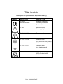
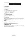
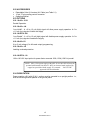
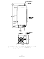
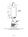
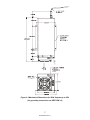
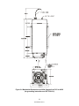
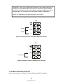
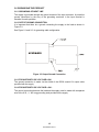
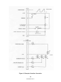
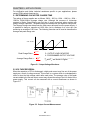
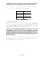
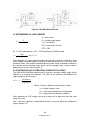
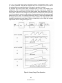
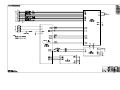
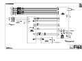
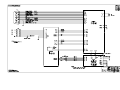
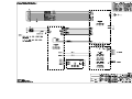
INSTRUCTION MANUAL FOR
500A/102A/152A/202A
POWER SUPPLY
Document: 83-493-001 Rev. K
TDK-Lambda Americas
405 Essex Road, Neptune, NJ 07753
Tel: (732) 922-9300
Fax: (732) 922-9334
Web: www.US.TDK-Lambda.com/HP
THIS PAGE INTENTIONALLY BLANK
ONE YEAR WARRANTY
TDK-Lambda Americas, Inc. (405 Essex Road, Neptune, N.J. 07753), warrants that the unit is free from defects in
material or workmanship for a period of ONE YEAR from the date of initial shipment. TDK-Lambda Americas Inc. will
service and, at its option, repair or replace parts which prove to be defective. This will be done free of charge during
the stated warranty period. This warranty excludes defects resulting from misuse, unauthorized modification,
operation outside the environmental or safety specifications of the power supply, or improper site preparation or
maintenance. The customer shall contact TDK-Lambda Americas Inc., for warranty service or repair as described in
the RETURNING EQUIPMENT section. The customer shall prepay shipping charges. If the unit is covered under the
foregoing warranty, then TDK-Lambda Americas Inc. shall pay the return shipping charges.
The “WARRANTY”, “CLAIM FOR DAMAGE IN SHIPMENT”, and “RETURNING EQUIPMENT” information applies to
equipment purchased directly from TDK-Lambda Americas Inc. End users receiving equipment from a third party
should consult the appropriate service organization for assistance with these issues.
THIS LIMITED WARRANTY IS IN LIEU OF, AND TDK-LAMBDA AMERICAS INC. DISCLAIMS AND EXCLUDES,
ALL OTHER WARRANTIES, STATUTORY, EXPRESS OR IMPLIED, INCLUDING, WITHOUT LIMITATION, ANY
WARRANTY OF MERCHANTABILITY OR FITNESS FOR A PARTICULAR PURPOSE, OR OF CONFORMITY TO
MODELS OR SAMPLES.
CERTIFICATION
All test and measuring equipment used by TDK-Lambda Americas Inc. for Final Acceptance Testing are traceable to
primary standards certified by the National Institute of Standards and Technology.
LETHAL VOLTAGES PRESENT!
All power supplies contain hazardous voltage and energy. The power supply must only be operated by qualified
personnel who have read this operator’s manual and are familiar with the operation, hazards and application of the
power supply. Proper care and judgment must always be observed.
1. Before connecting input AC power, ensure all covers are in place and securely fastened. Ensure the required
safety ground to chassis is installed and sufficient cooling is supplied.
2. Proper grounding from the input AC power is required to reduce the risk of electric shock, and to comply with
safety agency and code requirements.
3. Use extreme caution when connecting input AC power. Only apply the input voltage specified on the rating label.
4. Use extreme caution when connecting any high voltage cables. Never handle any output cables when the power
supply is operating.
5. After a power supply is switched OFF, its output section will retain a charge which may be lethal. Allow sufficient
time for self-discharge before handling anything connected to the output. The discharge time specified in the
Safety Notes does NOT include extra time required to discharge the energy stored in the user’s load.
6. When user serviceable fuses are present, always replace fuses with the same type and Volt/Amp rating.
7. Never attempt to operate the power supply in any manner not described in this manual.
8. Never remove DANGER or WARNING labels from the power supply. Replace lost or damaged labels
immediately. Contact TDK-Lambda Americas Customer Service for replacement labels.
9. The power supply may be serviced only by TDK-Lambda Americas Inc. factory qualified service personnel.
Breaking the warranty seal will void the warranty. Prior to opening the power supply, contact TDK-Lambda
Americas Inc. Customer Service for a written Service Waiver and a replacement warranty seal.
83-000-005 Rev F
TDK-Lambda
MANUFACTURER'S PRODUCT DECLARATION
INTENDED PURPOSE (USE)
The Power Supplies described by this manual are defined by TDK-Lambda Americas Inc.
as a component for use in the composition of an apparatus as defined in Article 1 (1) of
the EMC Directive (89/336/EEC). These products, as individual components, do not
perform in themselves a direct function for the user of the end product. They are not
intended to be placed on the market with a direct function to a final user! As such, the
products described by this manual are not subject to the provisions of the EMC Directive
(89/336/EEC, with amendment 92/31/EEC).
The products described by this manual are intended for incorporation into a final product
by a professional assembler. It is the responsibility of the assembler to ensure that the
final apparatus or system incorporating our products complies with all relevant EMC
standards for that final product.
OPERATING ENVIRONMENT
The operating environment as defined by TDK-Lambda Americas Inc., for the products
described by this manual is stated as follows:
The Power Supplies described by this manual are intended for use in a protected
industrial environment or in proximity to industrial power installations. These locations are
often referred to as industrial locations containing establishments that are not connected
to the low voltage public mains network.
Industrial locations are characterized by the existence of one or more of the following
conditions:
•
1) industrial, scientific and medical (ISM) apparatus are present;
•
2) heavy inductive or capacitive loads are frequently switched;
•
3) currents and associated magnetic fields are high;
•
4) location supplied by their own transformer.
These components are not intended for connection to a public mains network, but are
intended to be connected to a power network supplied from a high or medium-voltage
transformer dedicated for the supply of an installation feeding manufacturing or similar
operations. They are suitable for use in all establishments other than domestic and those
directly connected to a low voltage power supply network which supplies buildings used
for domestic purposes.
Page: 83-000-006 Rev D
TDK-Lambda
Description of symbols used in product labeling
SYMBOL
PUBLICATION
DESCRIPTION
EC Council
European Community
Directive 93/68/EEC
Conformity Assessment
Product Mark
IEC 348
Attention, consult
Accompanying documents
IEC 60417-1-5036
Dangerous voltage
IEC 60417-1-5019
Protective earth
(e.g. power line earth ground)
IEC 60417-1-5017
Functional earth
(e.g. chassis ground)
IEC 60417-1-5134
Electrostatic Discharge
(ESD) Sensitive Device
Page: 83-000-007 Rev E
ELECTRICAL STANDARDS
All company primary standards are either certified or are traceable to certification by the
National Institute of Standards and Technology.
CLAIM FOR DAMAGE IN SHIPMENT
This instrument received comprehensive mechanical and electrical inspection before
shipment. Immediately upon receipt from the carrier, and before operation, this instrument
should be inspected visually for damage caused in shipment. If such inspection reveals
damage in any way, a claim should be filed with the carrier. A full report of damage should
be obtained by the claim agent and this report should be forwarded to us. We will then
provide a disposition of the equipment and arrange for repair or replacement.
When referring to this equipment, always include the model and serial numbers.
The “WARRANTY”, “CLAIM FOR DAMAGE IN SHIPMENT”, and “RETURNING
EQUIPMENT” information applies to equipment purchased directly from TDKLambda Americas Inc. End users receiving equipment from a third party should
consult the appropriate service organization for assistance with these issues.
RETURNING EQUIPMENT
Before returning any equipment to the factory, the following steps shall be taken.
1.
Notify TDK-Lambda Americas Inc. at 732-918-6888 or follow the instructions at
www.US.TDK-Lambda.com/HP/service.htm. Give a full description of the difficulty
including the model and serial number of the unit in question. Upon receipt of this
information, we will assign a Return Material Authorization (RMA) number and
provide shipping instructions.
2.
The customer shall prepay shipping charges. Equipment returned to us must be
packed in a manner to reach us without damage. The shipping container must be
marked with the RMA number in an area approximate to the shipping label with
numbers that are easy to read. All returned units that do not show the RMA number
on the outside of the container will be refused.
If the equipment is repaired within the warranty agreement, than TDK-Lambda
Americas Inc. shall pay for the return shipping to the customer.
3.
For non-warranty repairs, we will submit a cost estimate for your approval prior to
proceeding. The customer shall pay return shipping charges.
MECHANICAL INSTALLATION
Most power supplies are heavy and, when rack mounted, they should be supported by
rails along the sides of the supply from front to rear. The rails must adequately support the
unit and not block airflow. Do not support the power supply from the front panel only.
Page: 83-000-011
Rev K
TABLE OF CONTENTS
CHAPTER 1 INTRODUCTION ........................................................................................................................1
1.1 DESCRIPTION.......................................................................................................................................1
CHAPTER 2 SPECIFICATIONS .....................................................................................................................2
2.1 AVERAGE CHARGING RATE ...............................................................................................................2
2.2 PEAK CHARGING RATE .......................................................................................................................2
2.3 NUMBER OF MODELS IN SERIES .......................................................................................................2
2.4 STANDARD VOLTAGE RANGES..........................................................................................................2
2.4.1 LINEARITY......................................................................................................................................2
2.4.2 ACCURACY ....................................................................................................................................2
2.5 POLARITY..............................................................................................................................................2
2.6 HIGH VOLTAGE ASSEMBLY ................................................................................................................2
2.7 INPUT CONNECTOR.............................................................................................................................2
2.8 INPUT CHART .......................................................................................................................................2
2.9 POWER FACTOR ..................................................................................................................................3
2.10 EFFICIENCY ........................................................................................................................................3
2.11 STORED ENERGY ..............................................................................................................................3
2.12 STABILITY ...........................................................................................................................................3
2.13 PULSE TO PULSE REPEATABILITY ..................................................................................................3
2.14 TEMPERATURE COEFFICIENT .........................................................................................................3
2.15 AMBIENT TEMPERATURE .................................................................................................................3
2.16 HUMIDITY ............................................................................................................................................3
2.17 PROTECTION......................................................................................................................................3
2.18 AGENCY APPROVALS........................................................................................................................3
2.19 TRANSIENT LINE PROTECTION........................................................................................................3
2.20 ESD ......................................................................................................................................................3
2.21 NOTE FOR PFC UNITS .......................................................................................................................3
2.22 ACCESSORIES ...................................................................................................................................4
2.23 OPTIONS .............................................................................................................................................4
2.23.1 Suffix –SYS ..................................................................................................................................4
2.23.2 Suffix –LH......................................................................................................................................4
2.23.3 SUFFIX –EN .................................................................................................................................4
2.23.4 Suffix -5V.......................................................................................................................................4
2.23.5 Suffix –LP......................................................................................................................................4
2.23.6 SUFFIX -110 .................................................................................................................................4
2.24 ORIENTATION.....................................................................................................................................4
CHAPTER 3 INSTALLATION .........................................................................................................................9
3.1 INITIAL INSPECTION ............................................................................................................................9
3.2 MOUNTING AND COOLING REQUIREMENTS ....................................................................................9
3.3 INPUT AC POWER ................................................................................................................................9
3.4 POWER CORD SPECIFICATION:.......................................................................................................10
3.5 CONNECTING HIGH VOLTAGE OUTPUT..........................................................................................11
3.6 GROUNDING THE PRODUCT ............................................................................................................12
3.6.1 GROUNDING OF INPUT LINE.....................................................................................................12
3.6.2 OUTPUT GROUND CONNECTION .............................................................................................12
3.6.3 FOR UNITS WITH O/P VOLTAGE ≤ 6Kv .....................................................................................12
3.6.4 FOR UNITS WITH O/P VOLTAGE > 6Kv:....................................................................................12
CHAPTER 4 OPERATION ............................................................................................................................13
4.1 REMOTE CONTROL............................................................................................................................13
4.2 INITITIAL CHECK-OUT PROCEDURE................................................................................................15
83-493-001 9
Rev. K
CHAPTER 5 APPLICATIONS .......................................................................................................................16
5.1 DETERMINING CAPACITOR CHARGE TIME.....................................................................................16
5.2 VOLTAGE REVERSAL ........................................................................................................................16
5.3 PARALLELING UNITS .........................................................................................................................17
5.4 MEASURING HIGH VOLTAGES .........................................................................................................18
5.5 DETERMINING AC LINE CURRENT ...................................................................................................19
5.6 CONTINUOUS HV DC OPERATION (CONSTANT VOLTAGE) ..........................................................19
5.7 LONG CHARGE TIME WITH POWER FACTOR CORRECTED (PFC) UNITS ...................................20
CHAPTER 6 MAINTENANCE AND CALIBRATION ....................................................................................21
6.1 SAFETY PRECAUTIONS.....................................................................................................................21
6.2 MAINTENANCE ...................................................................................................................................21
6.3 CALIBRATION .....................................................................................................................................21
LIST OF FIGURES
Figure 1-1 500A/102A/152A/202A Block Diagram.......................................................................... 1
Figure 2-1 Mechanical Dimensions for 500A, 102A, 152A Outputs up to 6KV ............................... 5
Figure 2-2 Mechanical Dimensions for 500A, 102A, 152A Outputs from 7KV to 40KV .................. 6
Figure 2-3 Mechanical Dimensions for 202A Outputs up to 6KV.................................................... 7
Figure 2-4 Mechanical Dimensions for 202A Outputs from 7KV to 40KV....................................... 8
Figure 3-1 Input AC Power Connection NON-PFC Version.......................................................... 10
Figure 3-2 Input AC Power Connection, PFC Version.................................................................. 10
Figure 3-3 Output Ground Connection.......................................................................................... 12
Figure 4-1 Example of Interface Connection ................................................................................ 14
Figure 5-1 Output Voltage Waveform .......................................................................................... 16
Figure 5-2 Output Current Measurement..................................................................................... 16
Figure 5-3 HV Bias Measurements............................................................................................... 19
Figure 5-4 Long Charge Time Operation ...................................................................................... 20
TABLES
Table 2-1: High Voltage Cable........................................................................................................ 2
Table 2-2: Input Voltage Chart........................................................................................................ 2
Table 2-3 Power Factor ................................................................................................................. 3
Table 4-1 Control Interface Connection for Standard 500A/102A/152A/202A Series .................. 13
Table 5-1 Output Capacitance ..................................................................................................... 17
83-493-00110
Rev. K
CHAPTER 1 INTRODUCTION
1.1 DESCRIPTION
The Series 500A/102A/152A/202A are High Voltage Switching Power Supplies designed
specifically for charging capacitors in laser systems and other pulsed power applications.
The 500A provides 500 J/s. the102A is 1000 J/s, 152A is 1,500 J/s, and the 202A
provides 2000 J/s of average power and can be paralleled indefinitely for higher total
system power. TDK-Lambda Americas Inc. also offers the 402 Series, 802 Series, and
303 Series rated at 4,000, 8,000 and 30,000 J/s respectively.
The 500A/102A/152A/202A power supplies incorporate a new high-frequency IGBT
parallel resonant inverter topology for efficient generation of the output power. A highperformance control module precisely regulates the output voltage, automatically
compensating for line, load, temperature, and rep rate variations. Normal external fault
conditions such as line dropout open or short circuit load, HV arc and over-temperature
will not damage the unit. The latest development in the parallel resonant inverter
topology and control circuitry also drastically improves pulse-to-pulse repeatability by
reducing the ripple or “bucket effect” even at very high pulse repetition frequencies. The
output voltages of the 500A/102A/152A/202A supplies are fully adjustable over each
range.
INPUT/POWER
High Freq.
Resonant
Inverter
PFC / Fuses
Inrush Limit
Step-up
Transformer
HV Rect.
HV Filter
Control
&
Aux. Power
Figure 1-1 500A/102A/152A/202A Block Diagram
1
83-493-001 Rev. K
HV OUTPUT
CHAPTER 2 SPECIFICATIONS
2.1 AVERAGE CHARGING RATE
500J/s, 1000J/s, 1500J/s, 2000J/s at rated Output Voltage
2.2 PEAK CHARGING RATE
550J/s, 1100J/s, 1650J/s, 2200J/s at rated Output Voltage
2.3 NUMBER OF MODELS IN SERIES
12 Standard (others at extra cost)
2.4 STANDARD VOLTAGE RANGES
1kV, 1.5kV, 2kV, 3kV, 4kV, 5kV, 5kV, 10kV, 15kV, 20kV, 30kV and 40kV. All models
continuously variable from 0 to 100% of rated output voltage.
2.4.1 LINEARITY
Linear to within 1% of full scale.
2.4.2 ACCURACY
1% of rated.
2.5 POLARITY
Available as fixed Positive or Negative
2.6 HIGH VOLTAGE ASSEMBLY
Insulating Medium/Cable
Voltage
1kV to 6kV
10kV to 40kV
Medium
Air
Oil
Output Cable
Coax. RG58
12 AWG, HV Silicon
Table 2-1: High Voltage Cable
2.7 INPUT CONNECTOR
VDE, UL approved.
2.8 INPUT CHART
Input Voltage selective by Terminal block position
Input Voltage (VAC) Current (No PFC)
Current (PFC)
Nameplate Design
500A 102A 152A 500A 102A
152A 202A
Range
Range
230
180-253 5A
10A 14.5A 3.5A 6.6A
10A 13.5
50/60Hz
50/60Hz
115
90-140
10A 20A 30A
7A
−
−
−
50/60Hz
50/60Hz
*Note: Input current ratings given are maximum when output Repetition Rate is
=>10Hz Consult Factory if model used at less than 10Hz.
Table 2-2: Input Voltage Chart
2
83-493-001 Rev. K
2.9 POWER FACTOR
Non PFC
0.65
All models
PFC
0.98
Table 2-3 Power Factor
2.10 EFFICIENCY
Better than 85%
2.11 STORED ENERGY
Less than 0.3 Joules all models
2.12 STABILITY
0.2% TO 300 Hz. For higher repetition rates, consult factory
2.13 PULSE TO PULSE REPEATABILITY
±0.2% TO 300 Hz. For higher repetition rates, consult factory
2.14 TEMPERATURE COEFFICIENT
100ppm per ºC
2.15 AMBIENT TEMPERATURE
Storage -40 to +85ºC. Operating -20 to +45ºC
2.16 HUMIDITY
90%, non-condensing
2.17 PROTECTION
The power supply is protected against Open Circuits, Short Circuits, Overloads and Arcs
2.18 AGENCY APPROVALS
500A/102A/152A are approved to UL 60601-1 and IEC 60601-1, Class I. 202A pending
approvals.
2.19 TRANSIENT LINE PROTECTION
Meets requirements of IEC 801-4, 801-5
2.20 ESD
All Remote Control Functions meet requirements of IEC 801-2
2.21 NOTE FOR PFC UNITS
When High Voltage is enabled by using either the “HV Enable” Line or deactivation of
the “Inhibit” Line the power supply will reach normal operation mode (and therefore all
other published specifications) within 50 ms.
3
83-493-001 Rev. K
2.22 ACCESSORIES
•
•
•
Detachable 8 feet (2.4 meters) HV Cable (see Table 2.1)
15 pin “D” plug mating control connector
Operating Manual
2.23 OPTIONS
2.23.1 Suffix –SYS
Parallel Operation
2.23.2 Suffix –LH
“Low Inhibit” - A +10 to 15 volt (high) signal will allow power supply operation. A 0 to
+1.5 volt (low) signal will inhibit the supply.
2.23.3 SUFFIX –EN
“Low Enable” - A +10 to 15 volt (high) signal will disable power supply operation. A 0 to
+1.5 volt (low) signal will enable the supply.
2.23.4 Suffix -5V
0 to +5 volt voltage (0 to full-scale output) programming.
2.23.5 Suffix –LP
Latching overload protection.
2.23.6 SUFFIX -110
100 to 120 VAC input option for power factor corrected 102A, 152A (1500 J/s) model.
NOTE: 102A, 152A power supply with suffix 110 at 100-120VAC must be
operated with internal 20A fuses F1 & F2 (on inverter board) replaced by
copper bus provided with the supply. Use external
30A UL/VDC
approved fuse/circuit breaker.
2.24 ORIENTATION
Power supplies >6kV with Oil H.V. section must be operated in an upright position. i.e.,
with the mounting bracket parallel to the ground plane.
4
83-493-001 Rev. K
D
Figure 2-1 Mechanical Dimensions for 500A, 102A, 152A Outputs up to 6KV
(for grounding instructions see SECTION 3.6)
5
83-493-001 Rev. K
Figure 2-2 Mechanical Dimensions for 500A, 102A, 152A Outputs from 7KV to 40KV
(for grounding instructions see SECTION 3.6)
6
83-493-001 Rev. K
Figure 2-3 Mechanical Dimensions for 202A Outputs up to 6KV
(for grounding instructions see SECTION 3.6)
7
83-493-001 Rev. K
Figure 2-4 Mechanical Dimensions for 202A Outputs from 7KV to 40KV
(for grounding instruction see SECTION 3.6)
8
83-493-001 Rev. K
CHAPTER 3 INSTALLATION
3.1 INITIAL INSPECTION
The shipping container should contain the following items: power supply, HV output
cable, male 15-pin “D” remote control connector and operator’s manual. Examine the
items immediately for damage. Locate the serial number label on the side of the power
supply and verify the model number, the input voltage rating and the output voltage
rating and polarity. In the event of any damage promptly notify the transportation
company and the TDK-Lambda Americas Inc. Customer Service Department.
3.2 MOUNTING AND COOLING REQUIREMENTS
The power supply can be mounted by the chassis support brackets (see Figure 2-1, 2-2,
2-3 and 2-4 for details). The mounting brackets are attached to the supply. The supply
must be mounted using four PHMS 8-32NC X 0.250 screws. Using wrong (longer)
screws may short HV parts to ground, causing permanent damage to power supply. The
power supply can also operate on a bench or table top. Power supplies >6kV with Oil
H.V. section must be operated in upright position i.e. mounting bracket parallel to ground
plane. In all cases adequate clearances must be provided for proper air flow and cable
bends. Keep the minimum HV cable bend radius greater than 4 inches (101.6mm) to
minimize stress on the insulation. Generally, at least 4 inches (101.6mm) of clearance
should be allowed at the inlet of the power supply and 2 inches (50.8mm) at the sides.
When operating in an enclosed system, care must be taken to ensure the ambient inlet
air to the power supply does not exceed the maximum operating temperature of 45ºC.
This often requires addition of a system heat exchanger.
3.3 INPUT AC POWER
Proper grounding from the input AC power is required to reduce the risk of electric
shock. The metal chassis of the power supply is grounded through the green earthing
wire at the input AC power terminal block. A protective ground connection by way of the
grounding conductor in the input terminal is essential for safe operation. Use extreme
caution when connecting input AC power and never apply the incorrect input power.
(Figure 2-1, 2-2, 2-3 & 2-4).
The PFC version and version without PFC should be connected as explained in the
following 2 paragraphs.
A.. Version with no PFC.
For this version, the supply can be connected to either 115VAC for 230VAC input
voltage (See table 2.2). These connections are shown in Figure 3-1.
For 115VAC connect the input line wires to L1 and COM terminals.
For 230VAC connect the input wires to L2 and COM terminals.
B. Version with PFC.
The PFC version connection is shown in Figure 3-2. Connect the input voltage line wires
to L2 and COM terminals.
9
83-493-001 Rev. K
WARNING: 102A, 152A AND 202A PFC Models are only available with 220 VAC
Nominal. For 152A Models Suffix 110 at 110-120 VAC must be operated with the
internal fuses F1 and F2 (on the Inverter Board) replaced by copper bus provided
with the supply. Use external 30A UL/VDC Approved Fuse/Circuit Breaker.
NOTE: For Application at less than 10 Hz, please see section 5.7.
TB1
L1
115 VAC
COM
230 VAC
L2
Figure 3-1 Input AC Power Connection NON-PFC Version
TB1
L1
COM
115-2 30 VAC
L2
Figure 3-2 Input AC Power Connection, PFC Version
3.4 POWER CORD SPECIFICATION:
Use wire with minimum .064 inches (1.6mm) diameter and 600 V insulation.
10
83-493-001 Rev. K
3.5 CONNECTING HIGH VOLTAGE OUTPUT
POTENTIAL LETHAL VOLTAGE
Ensure that the power supply is off and disconnected from the input power and never
operate the power supply without a load capacitor. Make sure that all load capacitors are
discharged and shorted to ground before making any connections. TDK-Lambda
Americas Inc. recommends the use of safety dump switches in high voltage discharge
circuits.
Never handle the HV cable during operation.
This power supply is designed to operate with a capacitive load. Operation of the power
supply without an external load capacitor may result in damage to internal circuitry.
Always use the HV connector and cable provided with the power supply or an equivalent
substitute provided by TDK-Lambda Americas Inc. Fully insert the connector end of the
HV cable and tighten the locking nut only “hand tight”.
NOTE: When operating above 20kV and/or 200 Hz rep. rate, ensure that silicone
grease (such as Dow Corning DC-4) is applied to the HV cable before insertion into the
HV connector. This displaces the air in the connector and reduces long term corona
effect.
Keep the minimum HV cable bend radius greater than 4 inches (101.6mm) to minimize
stress on the insulation. Keep the HV cable as distant as possible from the input power
and the input control signals.
Some peak current will flow out of the power supply during discharge and return through
the HV return and system chassis. This current comes from voltage reversal in under
damped systems and from normal discharge of filter and cable capacitance. The path for
this current should not parallel control signal returns since the resulting voltages could
interfere with normal system operation. The currents developed with voltage reversal at
high rep. rates, could damage the power supply. A resistor in series with the HV output
can be added to limit this current to an acceptable level. Refer to Section 5.2, Page 16
for more information.
The oil-filled HV assembly should not be opened. The oil and components have been
specially cleaned and vacuum impregnated at the factory and the assembly hermetically
sealed. Opening the assembly will compromise performance and void the warranty.
Tanks must only be serviced at TDK-Lambda Americas Inc.
11
83-493-001 Rev. K
3.6 GROUNDING THE PRODUCT
3.6.1 GROUNDING OF INPUT LINE
The supply is grounded through the ground terminal of the input connector. A protective
ground connection by the way of the grounding conductor in the input terminal is
essential for safe operation.
3.6.2 OUTPUT GROUND CONNECTION
It is important that there be a ground connecting the supply to the load as shown in
Figure 3-3.
See Figure 2-1 and 2-2, for grounding cable configuration.
Figure 3-3 Output Ground Connection
3.6.3 FOR UNITS WITH O/P VOLTAGE ≤ 6kV
The ground connection is made via the shield of the RG58 coaxial HV output cable
provided with the supply.
3.6.4 FOR UNITS WITH O/P VOLTAGE > 6kV:
The ground connection between the load and the supply must be made with a separate
wire to the 8-32, ½ “ NC long grounding stud provided on the supply.
12
83-493-001 Rev. K
CHAPTER 4 OPERATION
4.1 REMOTE CONTROL
The Series 500A/102A/152A/202A is easily controlled through the remote connector on
the input panel of the unit. Only the ENABLE/RESET, V PROGRAM and GND signals
are required for operation. The remaining signals are provided for status monitoring and
fault diagnosis. A schematic diagram showing the suggested interface circuit is shown in
Figure 4-1. This table is for a standard configuration.
PIN
SIGNAL NAME
I/O
DESCRIPTION
1
ENABLE/RESET
INPUT
A high signal (+10 to 15V) with respect to
ground (pin 14) will enable the power
supply. Latching faults can be cleared by
cycling this switch. Ground or open disables
the supply.
5
V PROGRAM
INPUT
A 0-10V signal with respect to ground at
this pin programs the output voltage
proportionally form zero to rated output.
7
VPEAK
OUTPUT
A 0-10V signal with respect to ground
proportional to the peak of the output
charging voltage. Can be used to drive a
meter displaying peak output voltage.
8
V ANALOG
OUTPUT
0-10V analog of output charging voltage
waveform.
10
INHIBIT
INPUT
A +10 TO 15V with respect to ground,
disables the unit. Open or ground allows
operation. This input can be used to disable
charging during HV switch recovery.
9, 11
+15V
OUTPUT
15V regulated. Can be used or user
programming applications 20mA max.
14
GND
OUTPUT
Control circuit return. Also chassis/earth
ground
15
INHIBIT LED
OUTPUT
Open collector. Indicates that the power
supply is receiving an INHIBIT signal.
13
EOC LED
OUTPUT
Open collector. Indicates that the power
supply is reaching end-of-charge, i.e. the V
PROGRAM set point.
3, 6
SUMMARY
FAULT LED
OUTPUT
Open collector. Indicates an output
overvoltage. Temperature fault or low input
voltage condition.
2
LOAD FAULT
OUTPUT
Indicates a shorted O/P or a very large load
capacitor.
Table 4-1 Control Interface Connection for Standard 500A/102A/152A/202A Series
13
83-493-001 Rev. K
Figure 4-1 Example of Interface Connection
14
83-493-001 Rev. K
4.2 INITITIAL CHECK-OUT PROCEDURE
LETHAL VOLTAGES PRESENT
ONLY QUALIFIED PERSONNEL TRAINED IN THE SAFETY ASPECTS OF
VOLTAGE SHOULD PERFORM INITIAL CHECKOUT PROCEDURES.
HIGH
The power supply should have no visible damage or defects and the cover should be
securely fastened. Properly connect the input power (Section 3.5), control connector
(Sec. 4.1) and HV output (Sec. 3.5, and 3.6).
If there is no load connected, the power supply will regulate the output voltage to the
programmed voltage level or sense an open circuit and immediately shut down
indicating a FAULT.
If there is a short circuit or overload condition on the output, the power supply will
operate in a 50% duty cycle protection mode and indicate a LOAD FAULT.
An overload condition can occur if the INHIBIT signal is missing, allowing HV switch to
latch-up. It can also occur if the discharge rep. rate is too high to allow the capacitor to
fully charge to V PROGRAM.
Double check all connections and ensure that all personnel are protected from the HV
output.
With the VPROGRAM at zero volts, turn the power supply on in the following sequence:
1.
2.
3.
4.
5.
6.
7.
8.
Connect power supply to the HV load.
Increase load rep. rate to prevent a full charge.
VPROGRAM signal (pin 5) at zero volts.
ENABLE/RESET signal (pin 1) at zero volts.
Assert ENABLE/RESET signal to 15V.
Verify HV output is at approx. zero volts.
Increase HV (by increasing VPROGRAM voltage) output slowly and verify
adjustability.
Decrease load rep rate to allow full charge.
15
83-493-001 Rev. K
CHAPTER 5 APPLICATIONS
For clarification and further technical assistance specific to your applications, please
contact TDK-Lambda Americas Inc.
5.1 DETERMINING CAPACITOR CHARGE TIME
The ratings of these supplies are as follows: 500A – 500 J/s, 102A – 1000 J/s, 152A –
1500J/s, 202A-2000J/s average charge rate. Although the measure of Joules/sec
equates to Watts, Stored Energy per unit time is more convenient when working with
energy storage capacitors. The peak charge rate determines the capacitor charge time.
The average charge rate determines the total power delivered from the power supply. It
is possible to charge a capacitor at 1650 J/sec, but to discharge it at a low rep. rate
producing an average of 100 J/sec. The following formulas can be used to determine the
average and peak charge rate.
V O L TA G E
Tc
Peak Charge Rate =
Tp
1
2
2 CV
Average Charge Rate =
Average Charge Rate =
C - OUTPUT LOAD CAPACITOR
TC
1
2
2 CV
Tp
TI M E
V - PROGRAMMED OUTPUT VOLTAGE
AND
P ARE SHOWN IN FIGURE
TTCC and
TPTare
shown in figure
Figure 5-1 Output Voltage Waveform
5.2 VOLTAGE REVERSAL
When the capacitor or PFN is discharged, a high peak current may flow out of the power
supply as a result of voltage reversal. This occurs in a system which is underdamped in
order to clear the high voltage switch after each pulse. The average value of this peak
current added to the normal output current may exceed the rating of the HV diodes in the
power supply. This current can be measured with a current transformer as shown in
Figure 5.2.
Figure 5-2 Output Current Measurement
16
83-493-001 Rev. K
A series terminating resistor (or series inductor or clamp diode) must be added as shown
if the average value of the peak current exceeds 110% of the normal output current.
When choosing Rs, ensure it can withstand the full output voltage across it as well as
the power dissipation caused by discharging Co (see Table 5.1) and Cc (20pF/ft) (65.62
pf/m) each cycle as well as conducting the normal output current. It’s power dissipation
can be calculated as Pd = (Io² Rs) + ½ (Co + Cc) V² (REP RATE).
Output Voltage
Co
1-2.8kV
60nF
3kV-6kV
15nF
10-30kV
460pF
40kV
230pF
Table 5-1 Output Capacitance
5.3 PARALLELING UNITS
The 500A/102A/152A/202A power supplies are designed for simple parallel operation.
The input power and HV output should be connected directly together. The REMOTE
connectors on the input panel can also be connected directly together using a “daisy
chain” ribbon cable from the system controller. Each of the power supplies operate at the
same time with the total charge rate equal to the sum of each.
Sometimes when operating several units in parallel, the high total power generates noise
which interferes with the power supply control. This is usually due to the many
interconnecting control cables acting as an antenna picking up noise. The problem
usually appears as one or more of the power supplies shuts down when the output
voltage increases beyond a certain level. Dressing the control cables as short as
possible and close to ground or using shielded cables should help. In severe cases, it is
necessary to wrap the cables several times through high permeability ferrite cores at the
input panel of each unit.
The 500A/102A/152A/202A power supplies can also be used as an Isolated High
Voltage continuous DC power source by adding an external filter capacitor. The value of
the filter capacitor depends upon the value of the allowable output voltage ripple value.
For parallel operation into DC loads, please contact TDK-Lambda Americas Inc.
Customer Service Department. (See Section 5.6).
17
83-493-001 Rev. K
5.4 MEASURING HIGH VOLTAGES
WARNING: EXTREME CAUTION MUST ALWAYS BE EXERCISED WHEN
TAKING ANY HIGH VOLTAGE MEASUREMENTS. IT SHOULD BE DONE ONLY
BY QUALIFIED PERSONNEL WHO ARE TRAINED IN THE SAFETY ASPECTS
OF WORKING WITH HIGH VOLTAGE.
A sample of the output voltage is available in the REMOTE connector. If it is desired to
measure the HV output externally, care must be taken to understand the accuracy of the
measurement.
When making a DC measurement, such as when the power supply is holding voltage on
a capacitor, any HV probe and DVM combination can be used. The Fluke 80K-40 probe
with any 10M input resistance DVM is adequate up to 40kV. Building a simple resistor
divider using appropriate HV resistors is also very straightforward. Keep in mind that all
HV resistors, including the one in the Fluke probe, exhibit a negative voltage coefficient,
changing by up to 4% from zero to max. voltage. Derating the resistors and calibrating at
the operating point solves this problem.
The value of the resistor R1 and R2 (Figure 5.3) can be calculated as follows:
VM =
R2
x Vo
R1 + R 2
where Vo is the High Voltage being measured.
Making a pulsed measurement with an oscilloscope requires a compensated HV probe
having a wide bandwidth. Simply connecting a DC probe, through the proper resistance,
into a scope yields a slow response only adequate for low rep. rate systems. As with DC
probes, the pulsed probe resistor voltage coefficient is a problem. In addition, damage to
the resistors can occur during pulsing due to high electric field gradients. Also, stray
capacitance to nearby objects can significantly alter the pulse response. For a highperformance, shielded probe to 40KV use a Tektronix P6015 or Ross Engineering
VD60-8.3-A-K-LB.
Measurements accurate to better than 0.1% can be achieved using a bias technique.
For example, if a 40V signal (40kV divided by 1000) is to be measured accurately, the
minus input of the DVM would be biased up 40V. The original signal, with respect to
ground, is fed to the plus input of the DVM. The bias can be measured accurately for
absolute measurements, or relative measurements read directly as the line or load is
varied. In the same manner, an oscilloscope return can be biased for accurate peak
measurements during pulsing.
18
83-493-001 Rev. K
Figure 5-3 HV Bias Measurements
5.5 DETERMINING AC LINE CURRENT
IL = Line current
IL =
P = Average output power
P
VL = Line voltage
VL PF X EFF
PF = Power factor (.65 min)
EFF = 0.85
Ex: A 152A operating from 115V – 10% and delivering 1000W average.
IL =
1000
x 0.9 = 17.5 A
(115)(.65)(0.85)
When charging very large capacitor banks requiring many seconds or minutes to reach
end-of-charge, the power supply will display a load fault and go into a 50% duty cycle
protection mode. If this feature is defeated and the power supply is allowed to charge for
an extended period, the peak output power, not the average power, must be used to
determine line current. (See Section 5.7).
5.6 CONTINUOUS HV DC OPERATION (CONSTANT VOLTAGE)
The 500A/102A/152A/202A supplies can be used as a constant voltage supply by the
addition of an external filter capacitor. The value of this capacitor will determine the
ripple voltage on the DC output.
Δ VPK − PK =
1.4( Po max)
Vo)(Co)( Fs )
Where: Po max = Maximum output power in watts
Vo = Output voltage in volts
Co = Total output capacitance in microfarads
Fs = Lowest switching frequency (40KHz)
When operating as a DC supply care must be taken not to draw more than the J/sec
rating of the unit.
Also, if the filter capacitor is inadvertently shorted, it may ring which can damage the
supply (Section 5.2).
19
83-493-001 Rev. K
5.7 LONG CHARGE TIME WITH POWER FACTOR CORRECTED (PFC) UNITS
It is advised that you consult the factory if this type of operation is required.
On supplies with active Power Factor Correction there is a limit to the length of the
charge time. With all capacitor charging supplies, the peak output power capability is
twice the joule per second rating. At pulse rates greater than approximately 20Hz, the
internal filter capacitors can average the power drawn from the power factor correcting
circuit. At lower pulse rates, the output stage will attempt to draw twice the rated average
power fro the PFC circuit. The internal current limit if the PFC circuit will be activated and
the supply will shut down. To avoid this type of fault condition, the output power can be
reduced by providing an inhibit pulse of fixed or variable duty cycle to keep the average
output within the PFC rating (See Figure 5.4).
Figure 5-4 Long Charge Time Operation
20
83-493-001 Rev. K
CHAPTER 6 MAINTENANCE AND CALIBRATION
6.1 SAFETY PRECAUTIONS
ONLY QUALIFIED PERSONNEL TRAINED IN THE SAFETY ASPECTS OF HIGH
VOLTAGE SHOULD PERFORM CALIBRATION.
The calibration steps described in this section require operation of the power supply with
the cover removed. Proceed with extreme caution as hazardous voltages are exposed
throughout the unit.
Safety glasses must be worn to prevent serious injury in the event of a component
failure (e.g., power transistors readily explode during fault conditions).
Because the power supply does not receive proper cooling with the cover removed, it
must be cooled by an external fan placed next to the supply to cool the inverter and HV
section (min. air flow 100 CFM (2.83 M3/min.)) when operating at full power. Operation
at full power with cover removed should be limited to less than five minutes.
6.2 MAINTENANCE
No maintenance is required under normal operating conditions. Occasional vacuum or
blow-out of the chassis may be required when operated in extremely dirty environments.
The oil-filled HV assembly must not be opened. The oil and components have been
specially cleaned and vacuum impregnated at the factory and the assembly hermetically
sealed. Opening assembly will compromise performance and void warranty. HV Tanks
must only be services at TDK-Lambda Americas Inc.
6.3 CALIBRATION
Calibration of the output voltage is accomplished with trim pot RP4 located on the control
board. This is the top PC board of the inverter assembly. RP4 is a 25 turn trimpot. Slowly
turn it clockwise to decrease the output voltage for a given VPROGRAM. Factory set for
10V rated voltage for standard version. Refer to Sections 4.1 and 4.2 of product
specification for Linearity and Accuracy.
21
83-493-001 Rev. K
Product Name:
UNIVOLT N 61 B
Revision Date: 20Mar2007
Page 1 of 9
______________________________________________________________________________________________________________________
MATERIAL SAFETY DATA SHEET
SECTION 1
PRODUCT AND COMPANY IDENTIFICATION
PRODUCT
Product Name:
UNIVOLT N 61 B
Product Description: Base Oil and Additives
Product Code:
730846-00, 97P847
Intended Use:
Electrical insulating oils
COMPANY IDENTIFICATION
Supplier:
EXXON MOBIL CORPORATION
3225 GALLOWS RD.
FAIRFAX, VA. 22037
USA
24 Hour Health Emergency
609-737-4411
Transportation Emergency Phone
800-424-9300
ExxonMobil Transportation No.
281-834-3296
MSDS Requests
713-613-3661
Product Technical Information
800-662-4525, 800-947-9147
MSDS Internet Address
http://www.exxon.com, http://www.mobil.com
SECTION 2
COMPOSITION / INFORMATION ON INGREDIENTS
Reportable Hazardous Substance(s) or Complex Substance(s)
Name
CAS#
HYDROTREATED LIGHT NAPHTHENIC DISTILLATE
(PETROLEUM)
64742-53-6
Concentration*
90 - 100%
* All concentrations are percent by weight unless material is a gas. Gas concentrations are in percent by volume.
SECTION 3
HAZARDS IDENTIFICATION
This material is considered to be hazardous according to regulatory guidelines (see (M)SDS Section 15).
POTENTIAL HEALTH EFFECTS
If swallowed, may be aspirated and cause lung damage. May be irritating to the eyes, nose, throat, and lungs.
Frequent or prolonged contact may defat and dry the skin, leading to discomfort and dermatitis.
Target Organs:
NFPA Hazard ID:
HMIS Hazard ID:
Skin |
Health:
Health:
0
0*
Flammability:
Flammability:
1
1
Reactivity:
Reactivity:
0
0
NOTE: This material should not be used for any other purpose than the intended use in Section 1 without expert
advice. Health studies have shown that chemical exposure may cause potential human health risks which may vary
from person to person.
Product Name:
UNIVOLT N 61 B
Revision Date: 20Mar2007
Page 2 of 9
______________________________________________________________________________________________________________________
SECTION 4
FIRST AID MEASURES
INHALATION
Remove from further exposure. For those providing assistance, avoid exposure to yourself or others. Use
adequate respiratory protection. If respiratory irritation, dizziness, nausea, or unconsciousness occurs, seek
immediate medical assistance. If breathing has stopped, assist ventilation with a mechanical device or use
mouth-to-mouth resuscitation.
SKIN CONTACT
Wash contact areas with soap and water. Remove contaminated clothing. Launder contaminated clothing
before reuse.
EYE CONTACT
Flush thoroughly with water. If irritation occurs, get medical assistance.
INGESTION
Seek immediate medical attention. Do not induce vomiting.
NOTE TO PHYSICIAN
If ingested, material may be aspirated into the lungs and cause chemical pneumonitis. Treat appropriately.
SECTION 5
FIRE FIGHTING MEASURES
EXTINGUISHING MEDIA
Appropriate Extinguishing Media: Use water fog, foam, dry chemical or carbon dioxide (CO2) to extinguish
flames.
Inappropriate Extinguishing Media: Straight Streams of Water
FIRE FIGHTING
Fire Fighting Instructions: Evacuate area. Prevent runoff from fire control or dilution from entering streams,
sewers, or drinking water supply. Firefighters should use standard protective equipment and in enclosed
spaces, self-contained breathing apparatus (SCBA). Use water spray to cool fire exposed surfaces and to
protect personnel.
Hazardous Combustion Products:
combustion products
Aldehydes, Oxides of carbon, Sulfur oxides, Smoke, Fume, Incomplete
FLAMMABILITY PROPERTIES
Flash Point [Method]: >145C (293F) [ ASTM D-92]
Flammable Limits (Approximate volume % in air): LEL: N/D
Autoignition Temperature: >315°C (599°F)
SECTION 6
UEL:
N/D
ACCIDENTAL RELEASE MEASURES
NOTIFICATION PROCEDURES
In the event of a spill or accidental release, notify relevant authorities in accordance with all applicable
regulations. U.S. regulations require reporting releases of this material to the environment which exceed the
reportable quantity or oil spills which could reach any waterway including intermittent dry creeks. The National
Product Name:
UNIVOLT N 61 B
Revision Date: 20Mar2007
Page 3 of 9
______________________________________________________________________________________________________________________
Response Center can be reached at (800)424-8802.
PROTECTIVE MEASURES
Avoid contact with spilled material. Warn or evacuate occupants in surrounding and downwind areas if
required due to toxicity or flammability of the material. See Section 5 for fire fighting information. See Section
3 for Significant Hazards. See Section 4 for First Aid Advice. See Section 8 for Personal Protective
Equipment.
SPILL MANAGEMENT
Land Spill: Stop leak if you can do it without risk. Recover by pumping or with suitable absorbent.
Water Spill: Stop leak if you can do it without risk. Confine the spill immediately with booms. Warn other
shipping. Remove from the surface by skimming or with suitable absorbents. Seek the advice of a
specialist before using dispersants.
Water spill and land spill recommendations are based on the most likely spill scenario for this material; however,
geographic conditions, wind, temperature, (and in the case of a water spill) wave and current direction and
speed may greatly influence the appropriate action to be taken. For this reason, local experts should be
consulted. Note: Local regulations may prescribe or limit action to be taken.
ENVIRONMENTAL PRECAUTIONS
Large Spills: Dike far ahead of liquid spill for later recovery and disposal. Prevent entry into waterways,
sewers, basements or confined areas.
SECTION 7
HANDLING AND STORAGE
HANDLING
Avoid contact with skin. Prevent small spills and leakage to avoid slip hazard.
Static Accumulator:
This material is a static accumulator.
STORAGE
Do not store in open or unlabelled containers.
SECTION 8
EXPOSURE CONTROLS / PERSONAL PROTECTION
EXPOSURE LIMIT VALUES
Exposure limits/standards for materials that can be formed when handling this product: When mists / aerosols
can occur, the following are recommended: 5 mg/m³ - ACGIH TLV, 10 mg/m³ - ACGIH STEL, 5 mg/m³ - OSHA PEL.
NOTE: Limits/standards shown for guidance only. Follow applicable regulations.
ENGINEERING CONTROLS
The level of protection and types of controls necessary will vary depending upon potential exposure conditions.
Control measures to consider:
No special requirements under ordinary conditions of use and with adequate ventilation.
Product Name:
UNIVOLT N 61 B
Revision Date: 20Mar2007
Page 4 of 9
______________________________________________________________________________________________________________________
PERSONAL PROTECTION
Personal protective equipment selections vary based on potential exposure conditions such as applications,
handling practices, concentration and ventilation. Information on the selection of protective equipment for use
with this material, as provided below, is based upon intended, normal usage.
Respiratory Protection: If engineering controls do not maintain airborne contaminant concentrations at a
level which is adequate to protect worker health, an approved respirator may be appropriate. Respirator
selection, use, and maintenance must be in accordance with regulatory requirements, if applicable. Types of
respirators to be considered for this material include:
No special requirements under ordinary conditions of use and with adequate ventilation.
For high airborne concentrations, use an approved supplied-air respirator, operated in positive pressure mode.
Supplied air respirators with an escape bottle may be appropriate when oxygen levels are inadequate,
gas/vapor warning properties are poor, or if air purifying filter capacity/rating may be exceeded.
Hand Protection: Any specific glove information provided is based on published literature and glove
manufacturer data. Work conditions can greatly effect glove durability; inspect and replace worn or damaged
gloves. The types of gloves to be considered for this material include:
If prolonged or repeated contact is likely, chemical resistant gloves are recommended. If contact with
forearms is likely, wear gauntlet style gloves.
Eye Protection:
If contact is likely, safety glasses with side shields are recommended.
Skin and Body Protection:
Any specific clothing information provided is based on published literature or
manufacturer data. The types of clothing to be considered for this material include:
If prolonged or repeated contact is likely, chemical, and oil resistant clothing is recommended.
Specific Hygiene Measures: Always observe good personal hygiene measures, such as washing after
handling the material and before eating, drinking, and/or smoking. Routinely wash work clothing and
protective equipment to remove contaminants. Discard contaminated clothing and footwear that cannot be
cleaned. Practice good housekeeping.
ENVIRONMENTAL CONTROLS
See Sections 6, 7, 12, 13.
SECTION 9
PHYSICAL AND CHEMICAL PROPERTIES
Typical physical and chemical properties are given below.
data.
Consult the Supplier in Section 1 for additional
GENERAL INFORMATION
Physical State:
Liquid
Color: Yellow
Odor: Characteristic
Odor Threshold: N/D
IMPORTANT HEALTH, SAFETY, AND ENVIRONMENTAL INFORMATION
Relative Density (at 15 C ):
0.88
Flash Point [Method]:
>145C (293F) [ ASTM D-92]
Product Name:
UNIVOLT N 61 B
Revision Date: 20Mar2007
Page 5 of 9
______________________________________________________________________________________________________________________
Flammable Limits (Approximate volume % in air): LEL: N/D
UEL: N/D
Autoignition Temperature: >315°C (599°F)
Boiling Point / Range:
260C (500F) - 371C (700F)
Vapor Density (Air = 1): > 5 at 101 kPa
Vapor Pressure: < 0.013 kPa (0.1 mm Hg) at 20 C
Evaporation Rate (n-butyl acetate = 1): N/D
pH: N/A
Log Pow (n-Octanol/Water Partition Coefficient): > 6.5
Solubility in Water: Negligible
Viscosity: 12 cSt (12 mm2/sec ) at 40 C | 3 cSt (3 mm2/sec) at 100C
Oxidizing Properties: See Sections 3, 15, 16.
OTHER INFORMATION
Freezing Point: N/D
Melting Point: N/A
Pour Point:
-40°C (-40°F)
DMSO Extract (mineral oil only), IP-346:
SECTION 10
< 3 %wt
STABILITY AND REACTIVITY
STABILITY: Material is stable under normal conditions.
CONDITIONS TO AVOID: Excessive heat. High energy sources of ignition.
MATERIALS TO AVOID:
Strong oxidizers
HAZARDOUS DECOMPOSITION PRODUCTS: Material does not decompose at ambient temperatures.
HAZARDOUS POLYMERIZATION: Will not occur.
SECTION 11
ACUTE TOXICITY
Route of Exposure
Inhalation
Toxicity (Rat): LC50 > 5000 mg/m3
Irritation: No end point data.
Ingestion
Toxicity (Rat): LD50 > 2000 mg/kg
Skin
Toxicity (Rabbit): LD50 > 2000 mg/kg
Irritation (Rabbit): Data available.
TOXICOLOGICAL INFORMATION
Conclusion / Remarks
Minimally Toxic. Based on test data for structurally similar
materials.
Elevated temperatures or mechanical action may form vapors,
mist, or fumes which may be irritating to the eyes, nose, throat, or
lungs. Based on assessment of the components.
Minimally Toxic. Based on test data for structurally similar
materials.
Minimally Toxic. Based on test data for structurally similar
materials.
Negligible irritation to skin at ambient temperatures. Based on test
data for structurally similar materials.
Eye
Irritation (Rabbit): Data available.
May cause mild, short-lasting discomfort to eyes. Based on test
Product Name:
UNIVOLT N 61 B
Revision Date: 20Mar2007
Page 6 of 9
______________________________________________________________________________________________________________________
data for structurally similar materials.
CHRONIC/OTHER EFFECTS
For the product itself:
Prolonged and/or repeated skin contact with low viscosity materials may defat the skin resulting in possible
irritation and dermatitis.
Small amounts of liquid aspirated into the lungs during ingestion or from vomiting may cause chemical
pneumonitis or pulmonary edema.
Contains:
Base oil severely refined: Not carcinogenic in animal studies. Representative material passes IP-346, Modified
Ames test, and/or other screening tests. Dermal and inhalation studies showed minimal effects; lung
non-specific infiltration of immune cells, oil deposition and minimal granuloma formation. Not sensitizing in test
animals.
Additional information is available by request.
The following ingredients are cited on the lists below: None.
1 = NTP CARC
2 = NTP SUS
SECTION 12
--REGULATORY LISTS SEARCHED-3 = IARC 1
5 = IARC 2B
4 = IARC 2A
6 = OSHA CARC
ECOLOGICAL INFORMATION
The information given is based on data available for the material, the components of the material, and similar materials.
ECOTOXICITY
Material -- Not expected to be harmful to aquatic organisms.
MOBILITY
Base oil component -- Low solubility and floats and is expected to migrate from water to the land.
Expected to partition to sediment and wastewater solids.
PERSISTENCE AND DEGRADABILITY
Biodegradation:
Base oil component -- Expected to be inherently biodegradable
BIOACCUMULATION POTENTIAL
Base oil component -- Has the potential to bioaccumulate, however metabolism or physical properties
may reduce the bioconcentration or limit bioavailability.
SECTION 13
DISPOSAL CONSIDERATIONS
Disposal recommendations based on material as supplied. Disposal must be in accordance with current applicable
laws and regulations, and material characteristics at time of disposal.
Product Name:
UNIVOLT N 61 B
Revision Date: 20Mar2007
Page 7 of 9
______________________________________________________________________________________________________________________
DISPOSAL RECOMMENDATIONS
Product is suitable for burning in an enclosed controlled burner for fuel value or disposal by supervised
incineration at very high temperatures to prevent formation of undesirable combustion products.
REGULATORY DISPOSAL INFORMATION
RCRA Information: The unused product, in our opinion, is not specifically listed by the EPA as a hazardous
waste (40 CFR, Part 261D), nor is it formulated to contain materials which are listed as hazardous wastes. It
does not exhibit the hazardous characteristics of ignitability, corrositivity or reactivity and is not formulated with
contaminants as determined by the Toxicity Characteristic Leaching Procedure (TCLP). However, used
product may be regulated.
Empty Container Warning PRECAUTIONARY LABEL TEXT: Empty containers may retain residue and can be
dangerous. DO NOT PRESSURIZE, CUT, WELD, BRAZE, SOLDER, DRILL, GRIND OR EXPOSE SUCH
CONTAINERS TO HEAT, FLAME, SPARKS, STATIC ELECTRICITY, OR OTHER SOURCES OF IGNITION; THEY
MAY EXPLODE AND CAUSE INJURY OR DEATH. Do not attempt to refill or clean container since residue is difficult
to remove. Empty drums should be completely drained, properly bunged and promptly returned to a drum
reconditioner. All containers should be disposed of in an environmentally safe manner and in accordance with
governmental regulations.
SECTION 14
TRANSPORT INFORMATION
LAND (DOT) : Not Regulated for Land Transport
LAND (TDG) : Not Regulated for Land Transport
SEA (IMDG) : Not Regulated for Sea Transport according to IMDG-Code
AIR (IATA) : Not Regulated for Air Transport
SECTION 15
REGULATORY INFORMATION
OSHA HAZARD COMMUNICATION STANDARD:
When used for its intended purpose, this material is classified as
hazardous in accordance with OSHA 29CFR 1910.1200.
NATIONAL CHEMICAL INVENTORY LISTING:
AICS, DSL, EINECS, KECI, TSCA
EPCRA: This material contains no extremely hazardous substances.
SARA (311/312) REPORTABLE HAZARD CATEGORIES:
Delayed Health.
SARA (313) TOXIC RELEASE INVENTORY: This material contains no chemicals subject to the supplier notification
requirements of the SARA 313 Toxic Release Program.
The Following Ingredients are Cited on the Lists Below:
Chemical Name
CAS Number
List Citations
Product Name:
UNIVOLT N 61 B
Revision Date: 20Mar2007
Page 8 of 9
______________________________________________________________________________________________________________________
HYDROTREATED LIGHT
NAPHTHENIC DISTILLATE
(PETROLEUM)
1 = ACGIH ALL
2 = ACGIH A1
3 = ACGIH A2
4 = OSHA Z
5 = TSCA 4
64742-53-6
4, 13
--REGULATORY LISTS SEARCHED-6 = TSCA 5a2
11 = CA P65 REPRO
7 = TSCA 5e
12 = CA RTK
8 = TSCA 6
13 = IL RTK
9 = TSCA 12b
14 = LA RTK
10 = CA P65 CARC
15 = MI 293
16 = MN RTK
17 = NJ RTK
18 = PA RTK
19 = RI RTK
Code key: CARC=Carcinogen; REPRO=Reproductive
SECTION 16
OTHER INFORMATION
N/D = Not determined, N/A = Not applicable
THIS SAFETY DATA SHEET CONTAINS THE FOLLOWING REVISIONS:
Revision Changes:
Section 09: Pour Point C(F) was modified.
Section 15: List Citations Table was modified.
Section 08: Exposure Limits Table was deleted.
Section 08: OEL Table - Form Column - Header was deleted.
Section 08: OEL Table - Limit Column - Header was deleted.
Section 08: OEL Table - Notation Column - Header was deleted.
Section 08: OEL Table - Source Column - Header was deleted.
Section 08: Exposure Limit Values - Header was deleted.
----------------------------------------------------------------------------------------------------------------------------------------------------PRECAUTIONARY LABEL TEXT:
Contains: HYDROTREATED LIGHT NAPHTHENIC DISTILLATE (PETROLEUM)
WARNING!
HEALTH HAZARDS
Repeated exposure may cause skin dryness or cracking. If swallowed, may be aspirated and cause lung damage.
Target Organs: Skin |
FIRST AID
Oral: Seek immediate medical attention. Do not induce vomiting.
Skin:
Wash contact areas with soap and water. Remove contaminated clothing. Launder contaminated clothing
before reuse.
FIRE FIGHTING MEDIA
Use water fog, foam, dry chemical or carbon dioxide (CO2) to extinguish flames.
SPILL/LEAK
Land Spill: Stop leak if you can do it without risk.
Recover by pumping or with suitable absorbent.
Water Spill: Stop leak if you can do it without risk. Confine the spill immediately with booms. Warn other
shipping. Remove from the surface by skimming or with suitable absorbents. Report spills as required to
appropriate authorities. Seek the advice of a specialist before using dispersants.
Use
Not intended or suitable for use in or around a household or dwelling.
Product Name:
UNIVOLT N 61 B
Revision Date: 20Mar2007
Page 9 of 9
______________________________________________________________________________________________________________________
----------------------------------------------------------------------------------------------------------------------------------------------------The information and recommendations contained herein are, to the best of ExxonMobil's knowledge and belief, accurate
and reliable as of the date issued. You can contact ExxonMobil to insure that this document is the most current
available from ExxonMobil. The information and recommendations are offered for the user's consideration and
examination. It is the user's responsibility to satisfy itself that the product is suitable for the intended use. If buyer
repackages this product, it is the user's responsibility to insure proper health, safety and other necessary information is
included with and/or on the container. Appropriate warnings and safe-handling procedures should be provided to
handlers and users. Alteration of this document is strictly prohibited. Except to the extent required by law,
re-publication or retransmission of this document, in whole or in part, is not permitted. The term, "ExxonMobil" is used
for convenience, and may include any one or more of ExxonMobil Chemical Company, Exxon Mobil Corporation, or any
affiliates in which they directly or indirectly hold any interest.
----------------------------------------------------------------------------------------------------------------------------------------------------Internal Use Only
MHC: 2A, 0, 0, 0, 0, 1
PPEC:
C
DGN: 2011629XUS (548632)
----------------------------------------------------------------------------------------------------------------------------------------------------Copyright 2002 Exxon Mobil Corporation, All rights reserved
01000680revD.sch-1 - Wed Jul 22 09:59:20 2009