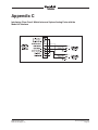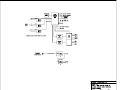
1
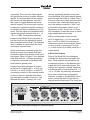
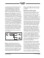
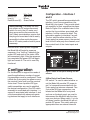
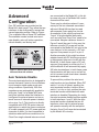
User Guide
Issue 2, September 2007
This User Guide is applicable for serial numbers:
M46-00180 and later
and units upgraded with software version 1.3 and higher
Copyright © 2007 by Studio Technologies, Inc., all rights reserved
www.studio-tech.com
50110-0907, Issue 2
This page intentionally left blank.
Table of Contents
Introduction ................................................................... 5
Installation ..................................................................... 10
Configuration ................................................................ 16
Advanced Configuration ............................................... 18
Operation ...................................................................... 20
Advanced Operation ..................................................... 25
Technical Notes ............................................................. 26
Specifications ................................................................ 28
Appendix A—Interfacing with Telex®/RTS®
Matrix Intercom Systems .............................................. 29
Appendix B—Interfacing with Riedel® Artist™
Matrix Intercom Systems .............................................. 30
Appendix C—Interfacing with Clear-Com®
Matrix Intercom Systems .............................................. 31
Block Diagram
Model 46 User Guide
Studio Technologies, Inc.
Issue 2, September 2007
Page 3
This page intentionally left blank.
Issue 2, September 2007
Page 4
Model 46 User Guide
Studio Technologies, Inc.
Introduction
The Model 46 is designed to interface
2-wire full-duplex party-line intercom circuits with 4-wire audio circuits associated
with matrix intercom systems. Other specialized audio system interfacing applications can also be supported. The Model
46 provides two independent full-featured
2-channel interfaces. Each interface contains two hybrid circuits which include
automatic nulling capability. The analog
circuitry, under software control, provides
excellent audio quality and high returnloss. The interfaces are compatible with
powered and unpowered 2-wire party-line
circuits. They are capable of supplying DC
power, allowing direct operation of devices
such as user belt packs. Configuration settings allow the 2-wire and 4-wire interface
circuitry to be compatible with a range
of nominal signal levels. Audio level meters provide user confirmation of system
performance during setup and operation.
Applications for the Model 46 include television sports and special event broadcasting, theme park and theater installations,
corporate events, and industrial testing
environments. Standard audio connectors
are used for all input and output signals.
The Model 46 mounts in one space
of a standard 19-inch rack enclosure
and requires 100-240 volts, 50/60 Hz for
operation.
2-Wire Interfaces
The Model 46’s 2-wire interfaces are
optimized for direct connection with dualchannel party-line (PL) intercom circuits.
In addition, single-channel party-line
intercom circuits can also be connected.
Many broadcast applications use the dualchannel TW-series from Telex®/RTS®,
including their popular BP325 belt pack.
Other industry-standard single- and dualchannel PL intercom systems, including
those from Clear-Com®, are also directly
compatible. To provide optimal signal
matching and interface performance the
nominal level of the Model 46’s 2-wire
interfaces can be selected. Using DIP
switches, accessible on the front panel,
the nominal levels can be selected to be
either –10 or –14 dBu, settings that should
allow compatibility with virtually all partyline systems. For example, for applications
that use equipment from RTS the –10 dBu
setting is appropriate. For other equipment, such as that from Clear-Com, the
–14 setting is correct.
Model 46 Front Panel
Model 46 Back Panel
Model 46 User Guide
Studio Technologies, Inc.
Issue 2, September 2007
Page 5
The Model 46’s 2-wire interfaces can
correctly function with powered (“wet”)
or unpowered (“dry”) intercom circuits.
Powered circuits have a DC voltage present, typically provided by power supplies
such as the RTS PS31 or Clear-Com
PS-232. This DC power, normally 30-32
volts, provides energy for connected
devices such as user stations or belt
packs. In this type of application the
Model 46 is configured to operate in its
external 2-wire power source mode. In this
mode the Model 46’s circuitry maintains
the required high-impedance load and,
as in all cases, draws no power from the
party-line circuit. An auto-terminate function ensures that should a “wet” circuit not
be connected, the Model 46’s interface
circuitry will remain stable. This unique
feature makes certain that objectionable
audio signals, including oscillations and
“squeals,” will infrequently be sent to the
connected 4-wire device.
A significant capability of the Model 46’s
2-wire interfaces is their ability to supply
DC power and 200 ohm AC termination
to the connected intercom circuits. Referred to as the Model 46’s internal 2-wire
power source mode, the 30 volt output
can power devices such as user stations
and belt packs. In many applications this
will eliminate the need for external intercom power supplies. Besides reducing
total system cost, this feature can also
lower system weight, reduce required
mounting space, and decrease the mains
energy requirement.
With each 2-wire interface’s ability to supply up to 300 milliamperes of current, a
typical broadcast application that uses two
sets of three BP-325 belt packs can easily
be supported. Each interface’s 30 volt DC
Issue 2, September 2007
Page 6
intercom power source ensures that systems requiring long intercom cable runs
will function correctly. The circuitry’s output regulation is such that little change in
the output voltage will occur over its entire
rated output current. Also, the unique design of the power supply circuitry virtually
eliminates the noise and “hiss” associated
with typical intercom power supply performance. Under software control the output
of the DC power supplies are monitored
for over-current and short-circuit conditions. This allows protection shut-down
of the output DC, as well as providing an
alert by way of a visual indicator.
Analog Hybrids with Auto
Nulling
A key reason that the Model 46’s interfaces achieve excellent audio performance
is the design of the 2-wire-to-4-wire hybrid
circuits. They provide low noise and distortion, good frequency response, and
high return-loss (“nulling”), even when
presented with a wide range of 2-wire
conditions. Unlike telephone-line (“POTS”)
oriented DSP-based hybrid circuits, the
Model 46’s analog circuitry provides extended frequency response. With a pass
band of 100 Hz on the low-end and 8 kHz
on the high-end, natural-sounding voice
signals can be sent to, and received from,
the 2-wire party-line circuits.
A hybrid’s ability to isolate the transmit
signal from the receive signal in the 2-wireto-4-wire interface is critical. The quality
of this isolation, technically known as
return-loss or trans-hybrid loss, is measured in dB. A high value is important,
especially in applications where multiple
2-wire-to-4-wire interfaces are used together. Remote sports broadcast applications
Model 46 User Guide
Studio Technologies, Inc.
are especially sensitive to this requirement.
The Model 46’s sophisticated auto nulling
function uses analog circuitry under microprocessor control to achieve significant
trans-hybrid loss. This return-loss “null” is
achieved by making a series of adjustments
to account for the resistive, inductive, and
capacitive conditions that are present on
the connected 2-wire party-line circuit. The
party-line’s conditions are the sum of the
impact made by the type and quantity of
cable, the connected user-devices, and
the intercom power source.
Whenever a user presses one of the Model
46’s “auto null” buttons digital circuitry adjusts the analog hybrids to rapidly achieve
their maximum return-loss. The nulling process takes less than 10 seconds for each
channel of an interface. However, it’s important to note that while the nulling process
is automatic, it only takes place upon user
request. This can lead to more stable and
consistent audio performance when a hybrid is exposed to the varying 2-wire conditions often found in broadcast applications.
The parameters obtained during the nulling
process are stored in non-volatile memory;
mains power interruptions won’t require the
auto nulling function to again be performed.
A sine-wave audio tone is generated for
use during the auto nulling process. The
frequency is software-controlled to maximize the ability of the hybrid circuits to
reach a “deep” null. In addition, at the
beginning of each auto null sequence a
short period of 24 kHz tone is sent to the
associated 2-wire party-line interface. This
serves as a microphone disable (“mic kill”)
signal for user devices such as the RTS
BP325. By automatically disabling “open”
microphones the auto nulling process can
achieve better performance.
Model 46 User Guide
Studio Technologies, Inc.
4-Wire Interfaces
Associated with the 4-wire portion of the
Model 46’s interfaces are analog line-level
inputs and outputs. These are intended
to interconnect with a variety of 4-wire devices, including matrix intercom systems,
audio-over-fiber transmission systems,
and other specialized audio equipment.
The input and output circuitry is transformer-coupled to minimize the chance of
hum, noise, or ground “loop” issues.
A key characteristic of the Model 46’s design is the ability to select the 4-wire input
and output nominal levels. This helps to
ensure compatibility with virtually all audio
equipment. Front-panel-accessible DIP
switches allow the nominal levels to be
configured from among four choices: 0,
+4, +6, or +8 dBu. The 0 dBu setting was
specifically provided for compatibility with
Clear-Com matrix intercom systems. The
+4 dBu setting allows “standard” audio
signals to be directly connected. Digital
matrix intercom systems from Riedel® can
be effectively connected using the +6 dBu
setting. And the +8 dBu setting allows
proper level matching with the popular
ADAM™ series of matrix intercom systems
from Telex/RTS. This setting also applies
to the related RVON-I/O VoIP product.
The Model 46 contains eight 5-segment
LED level meters. Four of the meters
are provided for each interface, with two
displaying the level of the signal being
received from the 4-wire source and
two displaying the level being sent to
the 4-wire output. During installation and
setup the meters are invaluable in helping to confirm that the nominal level DIP
switch settings have been properly made.
During normal operation the meters offer
rapid confirmation of audio signal flow in
Issue 2, September 2007
Page 7
and out of the unit. Additional LED status
indicators are also provided, offering a clear
view of the 2-wire DC power and auto null
functions.
Pro Audio Quality
The Model 46’s audio circuitry was designed in the spirit of professional audio
equipment, rather than that found in typical
party-line intercom gear. High-performance
components are used throughout, providing
low-distortion, low-noise, and high headroom. Using passive and active filters, the
frequency response is limited to approximately 100 Hz to 8 kHz. This range was selected to provide excellent performance for
human speech, while maximizing the ability
of the hybrids to create substantial “nulls.”
When the Model 46’s internal DC power
sources are selected to provide 2-wire
party-line intercom power, enhanced audio
performance can also be expected. The
quality of the DC supply circuits is excellent,
with very little noise, hum, or “hiss” being
added to the 2-wire connections. In addition, the impedance characteristics of each
interface’s DC powered (“wet”) channels
was tailored to be essentially identical to
that of the unpowered (“dry”) channel. This
unique situation allows the automatic nulling circuitry to provide excellent, consistent
results for both the powered and unpowered channels.
Attention to detail is a hallmark of the Model
46’s design. For example, during the brief
auto nulling process an interface channel’s
4-wire input and output signal is muted,
preventing unwanted audio from reaching
the connected equipment. Associated with
the 2-wire interfaces is circuitry that, under
software control, applies 200 ohm terminating impedances to the 2-wire party-line
Issue 2, September 2007
Page 8
circuits. This, along with other circuitry that
monitors DC voltages present on the
2-wire circuits, ensures that audio instability associated with unterminated circuits
will rarely occur. As previously mentioned
the Model 46’s 2-wire DC power sources
offer a unique level of performance. Their
ability to deliver power while maintaining
audio quality is simply unmatched.
Special Applications
While the Model 46 is designed to directly
integrate into typical applications, it’s
ready to support the “one-in-a-million”
situations too. To accomplish this DIP
switches, accessible on the back panel,
allow some of the automatic features to be
disabled. For example, one switch allows
the auto-terminate feature to be disabled.
While this feature can help maintain audio
quality, advanced users might need to disable it. This would allow full control over
the Model 46’s four hybrid circuits, enabling them to be used completely independently. A second DIP switch changes
the way in which the front-panel auto null
push button switches operate. Normally
pressing one of the buttons begins the
process of auto nulling both channels
associated with an interface. The alternate switch mode allows each auto null
sequence to be activated independently.
One tap of the auto null button will begin
the auto null process for interface one.
Two taps of the button will begin the auto
null process for channel two. For installerselected applications, three opto-coupled
inputs allow selected Model 46 features
to be remotely controlled. These features
include remote auto nulling for each interface and remote “mic kill” activation.
Model 46 User Guide
Studio Technologies, Inc.
Simple Installation
The Model 46 uses standard 3-pin XLRtype connectors to allow convenient interconnection in most broadcast and general
audio environments. For flexibility, access
to the 2-wire party-line intercom interfaces
can be made using the connectors provided on both the front and back panels.
In permanent installations the back-panel
connectors will typically be utilized. In
other settings, such as field television production, front-panel-access allows intercom belt packs to be rapidly connected,
without requiring access to the inside of a
rack enclosure or necessitating the use of
a secondary input/output (I/O) panel.
The Model 46 is housed in a rugged steel
enclosure that is designed to be “road
tough.” It mounts in one space of a standard 19-inch rack enclosure. The mains
input source can range from 100 to 240
volts, 50/60 Hz allowing direct operation
virtually anywhere in the world. A switchmode power supply, contained within the
Model 46’s enclosure, provides conversion of the mains input power into the DC
voltage required by the intercom power
supply circuits. Also contained within the
unit is a DC-to-DC converter that creates
the voltages required by the analog and
digital circuitry. These efficient power supplies help to ensure cool, reliable operation in a variety of settings.
Design Philosophy
While the “bits and pieces” that make
up the Model 46 have been described in
conventional terms, the real strength of
the unit rests in how it integrates and performs in the “real world.” Before beginning
the Model 46’s design process, conversations with industry experts quickly made it
Model 46 User Guide
Studio Technologies, Inc.
apparent that installing and configuring
existing 2-wire-to-4-wire interface units
was invariably a time-consuming, aggravating process that required the talent of an
expert to achieve reasonable results. And
even under those constraints the resulting
audio performance was often mediocre.
Any new design had to look at the application in a different way. This led to the overriding Model 46 design goal: create a “new
breed of cat,” fundamentally changing how
broadcast 2-wire-to-4-wire interface equipment fit into actual applications.
An important first step was to eliminate
the requirement that a senior technician,
along with a screwdriver, be present during every installation. (It was universally
acknowledged that their time can be better
spent elsewhere!) The need to adjust trim
potentiometers, fabricate special cabling
and connector straps, use nulling earpieces, etc. had to be eliminated. For example,
in virtually all instances, input and output
levels fall within just a few dB of their nominal values and, as such, could be supported with a limited number of configurable
choices. In addition, it was acknowledged
that in this application analog audio circuitry was capable of providing excellent
audio performance, but that the required
manual nulling process was operationally taxing. By adding digital control to the
analog circuitry, automatic nulling couldbe
performed—the best of both worlds!
The next step was to identify resources that
would improve the installation process and
make operation more reliable. This led to
the inclusion of multiple LED level meters,
allowing continuous monitoring of the input
and output signals. It also turned out that
in many applications only a small number
of user devices, such as belt packs, are
Issue 2, September 2007
Page 9
typically connected to 2-wire party-line
circuits. By adding DC power sources to
the Model 46’s 2-wire interfaces, the need
for external intercom power supplies could
often be eliminated.
The final step was to create a physical
package that would provide significant resources in a form that allowed simple and
reliable integration with other equipment.
This was accomplished by including two
2-channel interfaces in a one-rack-space
enclosure. Using standard 3-pin XLR-type
audio connectors would enable rapid
installation and troubleshooting. And by
making the Model 46 “universally” powered, installation in any locale could be
directly supported.
Installation
In this section you will be installing and
interconnecting the Model 46. The onerack-space unit will be mounted in an
equipment rack. Audio input, audio output, and party-line intercom connections
will be made by way of 3-pin XLR-type
connectors. AC mains power will be connected by means of a detachable cord
set that is compatible with the Model 46’s
3-pin IEC 320 C14-type inlet connector.
System Components
The shipping carton contains the Model
46 Interface and associated user guide.
Units destined for North America and
Japan also include an AC mains cord.
Your dealer or distributor should provide
an AC mains cord for other destinations.
Locating the Model 46
The Model 46’s mounting location will dictate the length of the cable runs needed to
Issue 2, September 2007
Page 10
link the unit with the connected devices.
This is really only a factor in relation to the
2-wire party-line intercom circuits. These
circuits carry unbalanced audio which
can be susceptible to interference and
crosstalk issues. Intercom circuits also
carry DC power which may make resistive
losses come into the picture. In general,
shorter intercom cable lengths will assure more reliable and consistent system
performance. Another location criterion is
access to the Model 46’s front panel. An
optimal location will allow convenient use
of the auto null push buttons and easy
observation of the status and level meter
LEDs.
Mounting the Model 46
Once a mounting location has been selected installation can begin. The Model
46 requires one space (1.75 vertical
inches) in a standard 19-inch (48.3 cm)
equipment rack. Secure the unit into
the equipment rack using two mounting
screws per side.
4-Wire Audio Inputs and
Outputs
Two audio line input and two audio line
output signals are associated with the
4-wire section of each of the Model 46’s
two interface circuits. Connections are
made using standard 3-pin male and
female XLR connectors. Refer to Appendices A, B, and C for details on interconnecting with Telex/RTS, Riedel, and
Clear-Com matrix intercom systems.
4-Wire Line Inputs
As previously mentioned, each of the
Model 46’s two interfaces allows two
analog line-level audio sources to be
Model 46 User Guide
Studio Technologies, Inc.
connected. The source for these signals
will typically be ports on a matrix intercom
system. It’s also possible that the signals
will come from other devices, such as a
fiber optic or copper-based audio transmission system. The 4-wire input circuitry
is balanced, capacitor coupled, transformer isolated, and has an impedance of 13 k
ohms. The line inputs are compatible with
signals that have a nominal level of 0, +4,
+6, or +8 dBu. Configuration switches,
located on the Model 46’s front panel, allow the circuitry to be adjusted to match
the connected nominal level. The switches
work in tandem to control both the input
and output nominal levels.
Audio sources are connected to the line
inputs by way of 3-pin female XLR-type
connectors which are located on the unit’s
back panel. Refer to Figure 1 for a detailed
view. Note that pin 1 of these connectors
is internally connected to the Model 46’s
earth/chassis ground point.
Prepare the mating connectors (males)
so that pin 2 is signal high (+ or hot), pin
3 is low (– or cold), and pin 1 is shield. If
connecting a source in this manner results
in hum or noise it’s possible that removing the shield connection from pin 1 can
eliminate the issue; “floating” pin 1 will
remove a potential ground current path
from the Model 46’s earth/chassis ground
point through the shield of a cable. Also, if
a hum or noise issue does arise be certain
to confirm that, unless absolutely necessary, the mating connector’s “shell” isn’t
connected to the cables’ shield or pin 1.
Termination of this “fourth” pin of a 3-pin
XLR connector is often the cause of seemingly inexplicable noise issues.
With an unbalanced source connect
pin 2 to signal high (+ or hot) and both
pins 1 and 3 to shield. If connecting an
unbalanced source in this manner results
in hum or noise, connect pin 2 to high
(+ or hot) and pin 3 to shield; leave pin 1
unterminated.
4-Wire Line Outputs
Each of the Model 46’s two interfaces
provides two analog line-level audio outputs. These outputs are intended to be
connected to inputs on the devices associated with the 4-wire audio signals. The
outputs are capacitor coupled, transformer balanced with a nominal level of 0, +4,
+6, or +8 dBu. As previously mentioned,
the 4-wire nominal level configuration
switches, located on the Model 46’s front
panel, control the level of both the line
outputs and the line inputs. The 4-wire line
Figure 1. Detail of back panel showing line inputs and outputs
Model 46 User Guide
Studio Technologies, Inc.
Issue 2, September 2007
Page 11
outputs are capable of driving inputs that
have impedances as low as 600 ohms,
however connecting to loads of 2 k ohms
or greater is preferred. The line outputs
are connected by way of 3-pin male XLRtype connectors which are located on the
Model 46’s back panel. Refer to Figure 1
for a detailed view.
The mating connectors (females) should
be prepared so that signal high (+ or hot)
is expected on pin 2. Signal low (– or cold)
should be expected on pin 3. The cables’
shields can be connected to pin 1. However, in order to minimize the chance that
ground-interaction problems will arise,
pin 1 on each of the line output connectors is isolated from all Model 46 circuitry
and ground points. “Floating” pin 1 virtually eliminates the chance that a “ground
loop” problem will occur.
2-Wire Party-Line Intercom
Connections
The Model 46’s 2-wire party-line (PL)
intercom interfaces are designed to directly connect with standard single- and
dual-channel party-line intercom devices.
Each of the two 2-channel PL interfaces is
compatible with intercom circuits that have
their own DC power sources. Alternately,
the Model 46 can provide the DC power
required by connected intercom user
devices. The internal 30 volt DC intercom
power source is limited to 300 milliamperes of current. This moderate amount
of power requires that the type and number of connected user devices be selected
appropriately.
For convenience, the 2-wire PL intercom
circuits can be connected to the Model 46
by way of four 3-pin male XLR-type connectors; two are located on the back panel
Issue 2, September 2007
Page 12
and two on the front. They are organized
in groups of two connectors per interface,
one on the back and one on the front.
They are wired in parallel (“multed”) and
provide access to the identical signals.
Dual-Channel Intercom Systems
If compatibility with RTS TW systems is
desired the mating connectors (females)
should be wired so that common is on
pin 1, DC with channel 1 audio is on pin
2, and channel 2 audio is on pin 3. This
wiring scheme is correct whether the connected devices are to be powered by an
external source or by means of the Model
46’s internal power sources.
Single-Channel Intercom Systems
There are two ways of connecting to the
Model 46’s 2-wire PL intercom connectors when compatibility with Clear-Com
single-channel intercom devices is desired. The most direct method is to prepare the female XLR mating connector so
that common is on pin 1, power is on pin
2, and audio is connected on pin 3. With
this connection scenario only audio channel two, associated with pin 3 of the Model
46’s 2-wire PL intercom interface connectors will be utilized. Pin 2, the Model 46’s
audio channel one, will only be used for
connecting DC power to the connected
devices. While the audio resources provided by channel one will not be used, the
Model 46 can still be used to supply DC
power on pin 2. As previously mentioned,
the maximum current draw on the 30 volt
DC output is 300 milliamperes. Alternatively, an external intercom power supply can
support the connected devices.
In some single-channel PL intercom system applications it may be desirable to
take full advantage of the two channels
Model 46 User Guide
Studio Technologies, Inc.
associated with each Model 46 interface.
In these applications one might want
to view the Model 46 as providing four
2-wire-to-4-wire interface circuits. The
Model 46 can certainly be used in this
fashion, but adapter cables will have to be
prepared. These adapters will “split” the
Model 46’s 2-wire PL intercom connectors
into two 3-pin male XLR connectors, one
for each audio channel. Pin 1 of the female
3-pin XLR intended to mate with the Model
46 will connect to pin 1 of both 3-pin male
XLR connectors. Pin 2 of the female XLR
will go to pin 3 of the male XLR designated
as channel 1. Pin 3 of the female XLR will
go to pin 3 of the male XLR designated as
channel 2. Refer to Figure 2 for details. Using two adapter cables the Model 46 can
be directly interconnected with four ClearCom intercom circuits. However, power for
the connected devices must be provided
by external power sources. The Model
46’s ability to supply intercom power will
not be utilized.
Refer to the Configuration and Advanced
Configuration sections of this user guide
for details.
Remote Control Inputs
The Model 46 allows connection of three
externally provided DC signals. These
signals can provide remote control operation of three functions: auto nulling for
interface 1, auto nulling for interface 2, and
a special “mic kill” function. Remote control of the auto nulling functions provides a
resource identical to that of the front-panel
pushbutton switches. The exact manner in
which the buttons and the remote control
inputs operate depends on the setting of
auto null button mode configuration DIP
switch. The “mic kill” function is unique,
only being available using the remote
control input. It causes a 500 millisecond
“burst” of 24 kHz signal to be sent sequentially to both of the 2-wire partly-line
interface channels associated with each
of the Model 46’s two interfaces. To clarify,
a “mic kill” signal is sent to a total of four
intercom channels whenever the function is activated. Independent control of
sending “mic kill” signals to interface 1 or
interface 2 is not supported. User intercom
devices compatible with this 24 kHz “mic
kill” signal include RTS TW-series beltpacks such as the BP325.
Figure 2. Adapter cable wiring diagram
Note: It’s critical that the correct configuration settings be made when using
the Model 46’s interfaces to support four
independent intercom circuits. Specifically,
the 2-wire power source configuration DIP
switches must be set for external. In addition the auto terminate disable DIP switch
must be placed in its on (up) position.
Model 46 User Guide
Studio Technologies, Inc.
The opto-coupled remote control inputs
are designed for direct connection with
3.3 and 5 volt DC logic signals. An internal
475 ohm resistor, in series with each optocoupler’s photodiode, acts to limit the
current flow. Signals of up to 32 volts DC
can be safely connected as long as the
current is limited to 20 milliamperes maximum. If necessary, an external resistor
can serve to limit the current. For example,
Issue 2, September 2007
Page 13
with a 12 volt DC signal using a 560 ohm,
¼-watt resistor in series with the connection would be appropriate. With a 24 volt
DC control signal a series resistor of 1.8 k
(1800) ohm is recommended. For correct
operation a minimum current of 2 milliamperes is recommended.
onto a piece of 10-conductor flat ribbon
cable. This ribbon cable can safely exit
the Model 46 by laying flat between the
chassis and the cover. The ribbon cable
can then “fan out” to loose wires or, better
yet, be terminated onto another connector
such as a 9-pin D-subminiature type.
Access to the remote control inputs
is provided by means of a 10-pin male
“header” connector which is located on
the Model 46’s circuit board. Refer to
Figure 3 for a view of the connector’s
location. The “keyed” and “shrouded”
header follows a common industrystandard specification: 2 rows of five pins
each with 0.1 inch between rows and pins.
The mating connector is intended to be
an insulation-displacement (IDC) socket
connector such as the AMP 746290-1. The
connector would be “crimp” terminated
There are several ways of preparing to
connect to the remote control inputs. The
easiest means is to purchase an interconnecting cable assembly from Studio
Technologies, Inc. The cable assembly
consists of a length of ribbon cable with
a 10-pin socket on one end and a 9-pin
D-sub female on the other. Contact the
factory or check the website for details.
Alternately, a competent technician can
easy fabricate an appropriate remote control input interconnect wiring assembly. An
example of a partially pre-made assembly
Figure 3. Location of 10-Pin male header connector on the Model 46 printed circuit board
Issue 2, September 2007
Page 14
Model 46 User Guide
Studio Technologies, Inc.
is part number A1AXH-1036G-ND which is
available from Digi-Key (www.digikey.com).
It’s important to ensure that the source
of the remote control signals can meet
the Model 46’s logic-state and timing requirements. The Model 46 recognizes an
idle remote control input as one that has
no current flowing through it. An active
remote control input is one that has current
flowing through it for a minimum of 30
milliseconds. A special case arises when
the auto null button operating mode has
been set to independent. This requires
one front-panel button “tap” to auto null
channel 1 and two button “taps” to auto
null channel 2. The remote control equivalent for one “tap” is current flowing for a
minimum of 30 milliseconds. The equivalent for two “taps” is current that flows
for 30 milliseconds, then a minimum nocurrent period of 30 milliseconds, followed
by current flow for a minimum of 30 milliseconds. The second period of current flow
must come within one second of the start
of the first.
Once the interconnect method and the
source of the control signals have been
selected, refer to Figure 4 for connection
details. Ensure that the connected signals
follow the specified polarity or damage to
the opto-coupled inputs may occur.
Function
Remote Auto Null Interface 1 +
It’s important that a competent technician be available to perform the actual
remote control input connection process.
As expected, mating the interconnecting
cable assembly with the Model 46’s 10pin “header” requires removing the unit’s
cover. As such, this must be done only
after confirming that all sources of mains
power have been disconnected from the
unit.
AC Mains Power
The Model 46 operates directly from AC
mains power of 100 to 240 V, 50/60 Hz.
As a “universal mains input” device, there
are no switches to set or jumpers to install.
A 3-pin IEC 320 C14-type inlet connector
on the Model 46 mates with a detachable mains cord set. For units shipped to
North America and Japan a cord is supplied that has a North-American (NEMA
15L) standard plug on one end and an
IEC 320 C13-type connector on the other.
Units bound for other destinations require
that the appropriate cord set be obtained.
The wire colors in the mains cord should
conform to the internationally recognized
color code and should be terminated
according to the following chart:
10-Pin
9-Pin D-Sub
Header (P9) Interface Cable
7
4
Remote Auto Null Interface 1 –
9
5
Remote Auto Null Interface 2 +
2
6
Remote Auto Null Interface 1 –
4
7
Remote “Mic Kill” +
6
8
Remote “Mic Kill” –
8
9
Figure 5. Detail of back panel showing AC
mains power connector
Figure 4. Remote control input pin-out chart
Model 46 User Guide
Studio Technologies, Inc.
Issue 2, September 2007
Page 15
Connection
Neutral (N)
Line (L)
Earth/Ground (E)
Wire Color
Light Blue
Brown
Green/Yellow
Safety Warning: The Model 46 does
not contain an AC mains disconnect
switch. As such, the AC mains cord
plug serves as the disconnection device. Safety considerations require that
the plug and associated inlet be easily
accessible to allow rapid disconnection of AC mains power should it prove
necessary.
As soon as AC mains power is applied
the Model 46 will begin its power-up
sequence. As a “boot up” indication the
power LED and each of the status LEDs
will momentarily light. After the sequence
has completed the power LED will again
light and remain lit. The unit is now fully
functional.
Configuration
For the Model 46 to support the needs of
specific applications a number of operating parameters must be configured. These
include the 2-wire party-line power source,
the nominal 2-wire level, and the nominal
4-wire level. Three 4-position DIP-type
switch assemblies are used to establish
the desired configuration. One DIP switch
assembly is associated with interface 1, a
second is associated with interface 2, and
a third associated with advanced operating features that apply to both interfaces.
Issue 2, September 2007
Page 16
Configuration – Interface 1
and 2
The DIP switch assemblies associated with
interface 1 and 2 are accessible on the
Model 46’s front panel. They provide identical capability for their respective interfaces.
Refer to Figure 6 for a detailed view. In this
section the four switches associated with
interface 1 will be covered in detail. This
information applies to interface 2 as well.
The four switches allow selection of the
2-wire party-line power source, the nominal
level for the 2-wire party-line channels, and
the nominal level of the 4-wire inputs and
outputs.
Figure 6. Detail of front panel showing four DIP
switches
2-Wire Party-Line Power Source
DIP switch 1 is used to select whether or
not the Model 46 provides DC power to
pin 2 of connectors associated with the
2-wire party-line intercom channels. Two
3-pin male XLR-type connectors, one
located on the Model 46’s front panel
and one on the back panel, are used to
interconnect the Model 46 with the intercom user devices. When switch 1 is in its
off (down) position the Model 46 will not
provide DC power. This switch setting is
appropriate when an external intercom
Model 46 User Guide
Studio Technologies, Inc.
power supply is providing power to the
intercom circuit. In addition to power, it’s
expected that the external power supply
will also provide the required 200 ohm terminating impedance to both pins 2 and 3.
When switch 1 is in its on (up) position the
Model 46 will provide a 30 volt, 300 milliamperes maximum source of DC power
to pin 2 of the 2-wire PL intercom connectors. The Model 46 will also provide 200
ohm terminating impedances for both pin
2 and pin 3 of the party-line connectors.
The DC power and termination capabilities allow direct powering of dual-channel intercom belt packs, such as the RTS
BP325. In addition, listen-only belt packs,
such as the Model 34 from Studio Technologies, Inc. can be directly connected.
There’s also no problem connecting
single-channel intercom belt packs or user
stations.
2-Wire Nominal Audio Level
DIP switch 2 allows adjustment of the
nominal audio level for the two 2-wire
party-line channels associated with interface 1. When the switch is in its off (down)
position the nominal level is –14 dBu.
This level is compatible with intercom belt
packs from manufacturers such as ClearCom. When the switch is in its on (up)
position the nominal level is –10 dBu. This
setting is appropriate when belt packs
from RTS, such as the BP325, or listenonly talent amplifier units from Studio
Technologies, Inc. are connected. For best
Model 46 performance it’s important that
the 2-wire nominal level selection be made
correctly.
Model 46 User Guide
Studio Technologies, Inc.
4-Wire Nominal Audio Level
DIP switches 3 and 4 are used to configure the nominal level of the input and output circuitry associated with interface 1’s
two 4-wire input and output connections.
Four level settings are available: 0, +4,
+6, and +8 dBu. Prior to setting these DIP
switches it’s important to determine the
nominal audio level of the equipment connected to the Model 46’s 4-wire input and
outputs. This may take a little investigation
but is important for obtaining the best possible Model 46 performance.
The 0 dBu setting is provided specifically
for use when a Model 46 is interconnected
with a Clear-Com matrix intercom system.
The +4 dBu setting is appropriate when
standard audio lines with “+4” nominal
levels are interconnected. The +6 dBu
setting can be appropriate when interconnecting with equipment manufactured in
Europe, such as the digital matrix intercom
systems from Riedel. The +8 dBu setting
is provided specifically when interconnecting the Model 46 with audio signals associated with an RTS ADAM-series of matrix
intercom system. This includes the related
RVON-I/O unit.
When DIP switches 3 and 4 are in their
off (down) position the nominal level is
set for 0 dBu. When switch 3 is on (up)
and switch 4 is off (down) the nominal
level is +4 dBu. When switch 3 is off
(down) and switch 4 is on (up) the nominal level is +6 dBu. When both switches
3 and 4 are in their on (up) position the
nominal level is configured for +8 dBu.
Issue 2, September 2007
Page 17
Advanced
Configuration
Four DIP switches are provided on the
Model 46’s back panel. They allow the two
interfaces to be configured for several advanced operating modes. Refer to Figure
7 for a detailed view of these DIP switches.
The available modes include auto terminate disable, auto null button operation,
refresh disable, and factory test.
Figure 7. Detail of back panel showing the
Advanced Mode DIP switches
Auto Terminate Disable
The auto terminate function is designed to
ensure that each 2-wire-to-4-wire interface
circuit remains stable under most operating conditions. Specifically, 200 ohm
impedances are automatically applied to
both pins 2 and 3 of a Model 46 2-wire
party-line interface when that interface is
configured for external power and no external source of intercom power is detected on pins 2 or 3. This function is directly
compatible with RTS TW-series intercom
applications in which the three conductors
of a cable support both DC power and two
channels of audio. It’s also compatible in
situations where all three conductors of a
Clear-Com single-channel intercom circuit
Issue 2, September 2007
Page 18
are connected to the Model 46. In this latter case only one of the Model 46’s audio
channels will be used.
There may be situations where it’s necessary for the two channels associated
with each Model 46 interface be used
with separate 2-wire party-line circuits.
An example of this might be where two
“loops” of single-channel belt packs,
such as units from Clear-Com, need to be
connected. Adapter cables as shown in
Figure 2 would be used. In this case the
intercom circuit’s DC power will not be
connected to the Model 46, but only to the
user devices. In this scenario, a DC voltage won’t be present on pin 2 or pin 3.
Another example of this might be where
adapter boxes with DC blocking are used
to interconnect intercom circuits with the
Model 46. In both these cases a DC voltage won’t be present on either pin 2 or 3
and the Model 46 will automatically apply
200 ohm terminations. In both these cases
the termination will be in error and will result in incorrect audio levels due a doubletermination condition.
To prevent this problem the auto terminate function can be disabled. When DIP
switch 1 is in its off (down) position the
auto terminate function is active. When
switch 1 is in its on (up) position the auto
terminate function associated with each
interface is disabled. Repeating for clarity,
the auto terminate disable function applies
to both interfaces 1 and 2. With the auto
terminate function disabled the two 46
interfaces, when set for external power,
will operate normally with the exception
that pins 2 and 3 will never be terminated
by the Model 46’s circuitry.
Model 46 User Guide
Studio Technologies, Inc.
The auto terminate disable function should
be used only when absolutely necessary;
it’s possible that a significant downside
could be experienced. With auto terminate
disabled it’s important that properly terminated 2-wire party line-intercom circuits
be connected to pins 2 or 3 on the Model
46’s 2-wire PL connectors. If they are not
connected, it’s likely that audio oscillations, noise, and distortion will be generated in the Model 46’s 2-wire-to-4-wire
converter circuitry. These audio artifacts
will not cause any damage, but will be
sent out the 4-wire line output connectors.
Users of the 4-wire equipment may be less
than pleased with what they hear!
Auto Null Button Operation
One pushbutton switch is associated
with each of the Model 46’s two interface
circuits. An advanced configuration parameter allows selection of the button’s
operation. The choices are dual auto null
mode and independent auto null mode.
When dual auto null mode is selected a
single “tap” (press and release) of one of
the two front-panel pushbutton switches
initiates a routine that begins with channel 1’s auto null sequence taking place
followed immediately by channel 2’s auto
null sequence being performed. Note that
the mode selected for auto null button operation will also apply to the remote auto
null inputs.
The independent auto null mode allows
the auto null function to be initiated for
each channel as desired. A single “tap”
will start the auto null routine for channel
1. Two “taps” will start the routine for
channel 2.
When DIP switch 2 is in its off (down) position the dual auto null mode is selected.
Model 46 User Guide
Studio Technologies, Inc.
This is provided specifically for cases
where the Model 46’s 2-wire party line
interfaces will be used with dual channel
intercom user devices. As an example: the
RTS TW-series provides two independent
audio channels, as well as power, over a
single 3-conductor cable. In a case such
as this it’s useful for both of the hybrid
circuits associated with an interface to
be auto nulled at approximately the same
time. The dual auto null mode allows a
single “tap” of the button to initiate nulling
of both hybrid circuits.
When DIP switch 2 is in its on (up) position the independent auto null mode is
selected. This would be appropriate for
applications in which the two audio paths
associated with each interface are used
with independent party-line intercom
circuits. This situation might arise when
two Clear-Com single-channel intercom
circuits are connected to one of the Model
46’s dual-channel interfaces. The hybrid
circuit associated with each channel can
be auto nulled as desired. Another example would be in an RTS TW-series application that uses source assignment panels.
The “SAP” panels would be used to route
multiple intercom channels to various sets
of user devices as desired. In this case,
the two channels associated with each
Model 46 interface will often end up not
routed to the same user device; independent auto nulling is certainly desired.
Refresh Disable
While testing the Model 46 as part of the
development process it was found that
in cases of extreme ESD (electro-staticdischarge or “static”) an integrated circuit
in the audio signal path could “latch up.”
This would result in the audio signal no
Issue 2, September 2007
Page 19
longer passing through this component
and on to the 4-wire audio output. Whenever this situation arose the component
was not damaged, but restoring the flow of
audio required either a power down/power
up sequence, an auto null operation, or a
change to one of the level configuration
DIP switches to take place. While it is very
unlikely that this type of ESD event would
occur during normal field operation it is of
concern for critical Model 46 applications.
To minimize the chance that the audio
path could experience this problem a
“refresh” routine was added to the Model
46’s operating software (“firmware”). To
ensure that the ESD-sensitive component
always remains functioning correctly the
software resends its operating instructions
four times each second. With this implementation the worst case scenario would
result in an audio loss of 250 milliseconds
or less in the event of an extreme ESD
“hit” being experienced.
But nothing comes without a price and in
this case the refresh routine adds a very
slight audio “tick” to the 4-wire output and
2-wire party-line signals. During typical
applications these refresh “ticks” will not
be noticeable. But there may be situations where any added audio artifact may
simply not be acceptable. To address this
possible, but highly unlikely, case backpanel DIP switch 3 can be used to disable
the refresh routine. When switch 3 is in its
off (down) position the Model 46 operates
in its standard fashion. When switch 3 is
in its on (up) position the refresh routine
is disabled. The Model 46 will continue to
function normally with the exception that
the four-times-per-second component
refresh routine will not occur. Goodbye
“click” but hello to the possibility that an
Issue 2, September 2007
Page 20
ESD-induced audio path problem could
occur. A good “rule of thumb” is that if a
Model 46 is mounted in an equipment rack
with a known-good ground connection,
disabling refresh shouldn’t pose any risk
to reliable operation. But if a unit is mounted in a portable rack, or used loose as a
single device, refresh should always remain
enabled. The reasoning is quite simple:
the latter condition is much more likely to
allow an ESD “hit” to dissipate into the
Model 46’s enclosure, while a substantial
rack enclosure will offer a low-impedance
path for ESD energy to dissipate into.
Factory Test
Back-panel DIP switch 4 is used to select
between normal mode and factory test
mode. When switch 4 is in its off (down)
position the Model 46 operates in its standard fashion. When switch 4 is in its on (up)
position the factory test mode is selected.
As expected, when the Model 46 is deployed in the field switch 4 should remain
in its off (down) position. No damage to
the Model 46 or connected equipment will
occur when factory test mode is active.
Operation
Technician intervention is typically not
required during normal Model 46 operation.
The unit is designed for continuous operation with no routine maintenance necessary.
Activating the auto null functions may be
warranted should connected user devices
or wiring associated with the 2-wire partyline intercom be changed. Upon power-up
the Model 46 will go through a short initialization sequence before normal operation
will begin. The power and status LEDs
will each light sequentially and, upon
Model 46 User Guide
Studio Technologies, Inc.
completion, the power LED will light
steadily. The settings for the four hybrid
circuits are stored in non-volatile memory
and will be recalled during the power-up
process.
Level Meters
The Model 46 contains eight 5-segment
LED level meters. These meters are provided as a support aid during installation,
configuration, operation, and troubleshooting. The meters represent the signals coming in from, and going out to,
the 4-wire connections. The meters are
organized in four groups each representing one input and one output. They are
calibrated to reflect the level in dB relative to the configured nominal operating
level. This is similar to the way in which
now-legacy VU meters functioned. As an
example let’s take the situation where the
nominal operating level of an interface is
configured for +4 dBu and an output (“to
4-wire”) LED labeled “0 dB” is lit. (For this
example, the level on the 2-wire PL circuit
is just large enough to light the “0” LED.)
This indicates that a signal with an approximate level of +4 dBu is present on the associated 4-wire output connector. Another
example would be a Model 46 interface
configured for +8 dBu operation and a
–12 dB LED is lit. This indicates that a
signal with audio level of –4 dBu is
present on its associated output.
Each level meter contains four green
LEDs and one yellow LED. The four green
LEDs indicate signal levels at or below the
configured nominal level. The top LED is
yellow in color and indicates a signal that
is 6 dB or greater than the nominal level.
An audio signal that causes the yellow
LED to light doesn’t necessarily indicate
Model 46 User Guide
Studio Technologies, Inc.
an excessive level condition, but it does
provide a warning that at some stage
reducing the signal level may be prudent.
Normal operation with normal signal levels
should find the meters lighting near their
0 dB point. Signal peaks may cause the
yellow LEDs to flash. But a yellow LED that
lights fully during normal operation will
typically indicate a signal level or configuration problem.
If the “from 4-wire” meters display consistency lower or higher levels than their 0 dB
points it’s possible that a configuration issue exists. One potential problem is incorrectly set 4-wire nominal audio level DIP
switches for one or both of the Model 46’s
interfaces. If the nominal level is set too
low then sufficient audio headroom might
not be available. It can also result in excessively-high audio signals being sent to
2-wire party-line circuits. Setting the nominal level for too high a value will reduce
the signal-to-noise performance. And, as
expected, it may also result in audio signals being sent to the 2-wire circuits at
too low a level. Begin a review by confirming that the two 4-wire level DIP switches
associated with each interface are set as
required.
If the Model 46’s 4-wire nominal levels
are set correctly but the meters still reflect
sub-optimal levels, the issue may be related to incorrect settings on the equipment
connected to the 4-wire inputs and outputs. It’s possible that although a connected 4-wire device’s nominal level matches
the Model 46’s level setting, its actual
nominal level may be significantly different. With a digital matrix intercom system
this problem could be due to an incorrect
configuration having been made to a specific channel or port. For example, the RTS
Issue 2, September 2007
Page 21
ADAM system has a published nominal
level of +8 dBu, but using its configuration
software it’s possible to set panels or ports
to a level different than nominal. The best
solution in this case is to adjust the intercom system so that its levels comply with
its own published nominal. This should,
at least in theory, lead to the best system
performance, including correct interfacing
with the Model 46. But often it’s impossible to “clean up” the levels of a existing
system. In this case it may be necessary
to revise the Model 46’s 4-wire nominal
level settings to match the reality of the
connected signals.
of at least 6 dB. Removing the unwanted
termination is really the only valid means
of correcting the problem.
The “to 4-wire” meters display the level
of signals that come from the 2-wire partyline circuits and go out the 4-wire interfaces. An issue may arise if the signals
coming from the connected party-line
user devices aren’t at a sufficient level
so that a normal meter display can be
reached. This could be the result of an
incorrectly configured 2-wire nominal
audio level. Confirm that the DIP switch,
associated with each interface, is set to
match the nominal level of the connected
devices. RTS user devices have a nominal
level of –10 dBu; Clear-Com devices typically have a –14 dBu nominal level.
External Power Source
When set for an external 2-wire power
source, the Model 46 will not provide
power on pin 2 of the 2-wire connectors,
nor will the Model 46 use any power from
a connected intercom circuit. As expected,
audio signals will be sent from, and received by, each interface’s two audio circuits. In this mode of operation the Model
46 acts as a typical user station on the
connected intercom circuit.
It’s also possible that an error is present on the 2-wire party-line circuit. Signal
levels associated with 2-wire party-line
circuits depend on a single termination
being present. This termination, typically
200 ohms, is almost always made at the
power supply source. But it’s possible
that another device, such as a second
active power supply on the same circuit,
will cause a “double-termination” condition. This leads to a nominal 100 ohm line
impedance which will result in a level drop
Issue 2, September 2007
Page 22
Connecting Party-Line
Devices
The Model 46’s two dual-channel interface
circuits allow two sets of user devices to
be connected. Depending on the setting
of the configuration DIP switches, either
an external intercom power source or the
Model 46’s internal 2-wire power source
has been designated for supporting the
connected user devices.
As a connection confirmation, hardware
and software in the Model 46 monitors
pins 2 and 3 of the 2-wire PL intercom
connectors for the presence of DC voltage. A level greater than approximately
18 volts DC on pin 2 will cause the status
LED labeled pin 2 to light. A level greater
than 18 volts DC on pin 3 will cause the
pin 3 status LED to light.
The author is aware that user intercom
devices almost always draw power from
pin 2 rather than pin 3. However, in many
broadcast applications, power is provided
on all intercom paths so that flexible channel assignments can be made. In the
Model 46 User Guide
Studio Technologies, Inc.
external 2-wire power mode the Model 46
is simply an observer; whether intercom
power is present on pin 2, pin 3, or both
pins 2 and 3 is not significant.
mount component technology and have
a lower maximum current draw of 65 milliamperes. Four of these “modern” BP325
units can easily be supported.
So that the Model 46’s 2-wire-to-4-wire
interface circuits remain stable and don’t
generate audio artifacts, an auto terminate
feature is implemented. This maintains a
200 ohm termination on both pins 2 and 3
so long as neither of the 2-wire power status LEDs is lit. To clarify, if either, or both,
the LEDs are lit then both terminations
are removed. It was felt that this method
would provide a fairly accurate indication
that an active intercom circuit is connected. In this case the 200 ohm termination is
expected to be provided elsewhere, typically as part of the external power supply,
and the Model 46’s termination is “lifted.”
The Model 46’s intercom power supply
circuits operate under software control.
This allows detection of fault conditions
and protection of both the Model 46’s
circuitry and connected intercom user
devices. Upon initial Model 46 power
up no monitoring of the intercom power
output takes place for a period of five
seconds. This allows the Model 46’s
circuitry and the connected intercom user
devices to stabilize. The LED associated
with pin 2 will light to indicate that the
output is active. After this initial 5-second
period monitoring becomes active. A fault
condition is detected if the power on pin
2 falls below 24 volts for a continuous one
second interval. The hardware and software responds to this condition by turning
off the power source to pin 2 and flashing
the pin 2 LED as a warning. After a five
second “cool down” interval the output returns to the same condition as upon initial
power up: power is again applied to pin 2,
the pin 2 status LED will light, and monitoring won’t begin for another five seconds. A full short-circuit condition applied
to the Model 46’s 2-wire connectors will
result in a continuous cycle of 6 seconds
on (5 seconds for start up and one second
for detection) and 5 seconds off.
Internal Power Source
When an interface’s front-panel DIP switch
is set for internal 2-wire power the Model
46’s 2-wire party-line interface supplies
30 volt DC on pin 2 of the output connector. A maximum current draw of 300
milliamperes is available. This current is
sufficient to power various intercom user
devices such as small user stations and
belt packs. A common broadcast application would be to use RTS BP325 belt
packs. Select the connected devices so
that their total current doesn’t exceed 300
milliamperes. That’s not always the easiest
figure to calculate but a web search will
generally find specifications for all commonly used devices. For example,
a search finds that the original version
of the BP325 consumes a maximum of
85 milliamperes of current. According to
this figure up to three of these units can
be connected to each Model 46 interface.
Newer versions of the BP325 use surface
Model 46 User Guide
Studio Technologies, Inc.
As a diagnostic aid the 2-wire power
status LED associated with pin 3 remains
active in the internal power mode. Whenever DC in excess of approximately
18 volts is present on pin 3 the LED will
light. This condition will normally never
exist but could prove useful in special
circumstances.
Issue 2, September 2007
Page 23
Auto Null
Each of the Model 46’s dual-channel interfaces has circuitry to automatically null the
two 2-wire-to-4-wire interfaces. Normally
this process is performed at the time of
initial Model 46 configuration but there’s
no reason why “auto nulling” can’t be initiated anytime one desires. The only time
that auto null must be performed is if conditions have changed vis-à-vis the intercom user devices and wiring connected to
a Model 46 2-wire PL interface connector.
Even a slight change to an intercom circuit, such as adding or removing a section
of cable, is sufficient to require that the
auto null process be performed.
Two buttons, one associated with each
interface, are provided to activate the
auto null process. Refer to Figure 8 for a
detailed view. To initiate auto null simply
requires pressing and releasing (“tapping”) a button. The process begins by
nulling channel one of an interface and,
when completed, moves on to channel
two. Two LEDs provide a visual indication
of the auto null process, flashing when the
auto null process for its respective channel is active.
Figure 8. Detail of front panel showing auto null
section
Issue 2, September 2007
Page 24
An actual auto null sequence starts by
muting the 4-wire input and output signal
paths associated with the specific channel
to be nulled. Then a short period of 24 kHz
signal is sent out the 2-wire PL intercom
interface channel. This will turn off microphones on those connected user devices
that are compatible with the RTS TWseries “mic kill” protocol. The actual auto
nulling process will next be performed. A
series of tones will be sent out the 2-wire
interface. Other Model 46 circuitry, under software control, will rapidly perform
adjustments to achieve the best null possible. After the adjustments are made the
results are stored in non-volatile memory.
Once the process has completed the
4-wire input and output paths are again
activated.
Advanced configuration DIP switch 2,
located on the back panel, allows an
independent auto null button mode to
be selected. If switch 2 is in its on (up)
position, the front-panel pushbuttons will
function in quite a different manner. In the
independent mode, a single “tap” to a
switch will cause channel 1 to auto null.
Two “taps” will cause channel 2 to auto
null. By observing the operation of the two
auto null status LEDs it will become readily
apparent which of the button modes has
been selected.
If possible, prior to performing an auto
null it’s polite to warn all personnel who
are actively using the connected intercom
devices. The tones sent to the 2-wire intercom circuit during the nulling process
are not excessively loud or obnoxious,
but most users might want to remove
their headsets during the process. In
addition to warning users, it might be
a good time to ask them to mute any
Model 46 User Guide
Studio Technologies, Inc.
active microphones. While the automatic
“mic kill” signal will apply to many user
devices it may not apply to all. Muting
microphones is significant as obtaining a
“deep” null requires that no extraneous
signals be present on the intercom circuit.
Advanced
Operation
The Model 46 allows several of the operating parameters to be configured to meet
the needs of specific applications. The
following paragraphs provide details about
the auto terminate disable and factory
test modes.
Auto Terminate Disable
As previously discussed in this user guide,
the auto terminate function can come into
play when a 2-wire interface is configured
for external power. Using a combination
of hardware and software, pins 2 and 3
of each 2-wire PL intercom connector are
monitored for the presence of DC voltage.
If a level of greater than approximately
18 volts DC is not detected on either pin,
200 ohm terminating networks are applied
to those same pins. This ensures that the
Model 46’s hybrid circuitry remains stable,
preventing objectionable audio signals
from being sent to the 4-wire output connectors. One caveat does apply; there
may be a few seconds of severe noise
whenever an interface moves from a DC
present condition to a DC not present
condition. But other than that period, the
audio paths will remain “clean.”
Model 46 User Guide
Studio Technologies, Inc.
As a visual aid, LEDs on the front panel
will display the DC power status of pins
2 and 3. But when auto terminate disable
mode is active the LEDs will no longer
indicate the intercom circuit’s termination
status.
For special externally powered 2-wire applications the auto terminate function can
be disabled. This primarily will come into
play when “splitting” the Model 46’s resources into four separate single-channel
interfaces. Moving advanced configuration
DIP switch 1, located on the Model 46’s
back panel, to its on (up) position disables
the auto terminate function. To someone
observing only the Model 46’s front panel
this change would not be readily apparent. The front-panel LEDs will continue to
display the DC power status of pins 2 and
3. But whether or not either or both LEDs
are lit, the Model 46 will never apply 200
ohm terminations to pins 2 or 3. For the
hybrid circuits to remain stable termination impedances must be provided by the
connected circuits. If these are not present one should expect the hybrid circuits
to generate a very impolite noise. This
condition, caused by the 2-wire output
circuitry being in an “unloaded” state, will
not damage the Model 46’s circuitry. But
errors in cable “patching,” a disconnected
cable, or other real-world issues, can lead
users listening to signals that originate in
the Model 46’s 4-wire outputs from being
presented with a rude surprise!
In conclusion, it’s important that technical
personnel working with the Model 46 be
informed when the auto termination function has been disabled. They will then be
aware of the potential noise issues and be
ready to make corrections should a problem arise.
Issue 2, September 2007
Page 25
Factory Test Mode
Back-panel DIP switch 4 allows a factory
test mode to be enabled. During normal
operation switch 4 should remain in its off
(down) position. When switch 4 is in its on
(up) position factory mode is active. Enabling this mode will result in the following
operating condition: during an auto null
sequence the associated 4-wire output
channel will remain active. This will allow
the tones associated with the nulling process to be present on the 4-wire output.
While not appropriate during actual Model
46 use, it is interesting to “hear” the nulling process take place. But unless directed by factory personnel switch 4 should
remain in its off (down) position.
Technical Notes
Software Version Display
A special Model 46 power-up sequence
allows the unit’s software version number
to be displayed. This is useful when working with factory personnel on application
support and troubleshooting situations.
The four status LEDs associated with
interface 1 are used to display the major
release number with a range of 1 through
4. The four status LEDs associated with
interface 2 are used to display the release
sub-number which again ranges from 1
through 4. Refer to Figure 9 for a detailed
view of the status LEDs and the corresponding software version numbering
scheme. The Model 46’s initial software
release is version 1.1 which is represented
by the bottom LEDs of each status column
being lit.
Interface 1 LED Section
(Major Release Number)
Interface 2 LED Section
(Release Sub-Number)
O 4
.4 O
O 3
.3 ●
O 2
.2 O
● 1
.1 O
Figure 9. Detail of front panel showing the status LEDs that display the software version. In this
example, the software version is 1.3.
Issue 2, September 2007
Page 26
Model 46 User Guide
Studio Technologies, Inc.
To display the Model 46’s software version
is very simple. From the powered-down
state, press and hold the auto null button
associated with interface 1. Apply mains
power while continuing to press the button. The normal power-up sequence will
not occur but instead one LED will be lit in
the column associated with interface 1 and
one LED will be lit in the column associated
with interface 2. As previously described,
these two LEDs represent the unit’s current
software version. While the software version
number is being displayed the LED level
meters will likely display random readings.
This is not a problem and can simply be
ignored. After the software version number
has been “read” the auto null button can
be released. At this time the unit will begin
its normal power-up sequence.
Note that while it’s easy to determine which
software version is loaded into the Model
46 a trip back to the factory is required to
update it. The 8-bit microcontroller that
provides the unit’s logic “horsepower” also
includes internal FLASH memory. This nonvolatile memory is used to store the operating software (“firmware”). Re-programming
this memory requires using a specialized
programming unit. While not outrageous in
price, it still costs in the range of US$500.
The “programmer” uses a ribbon cable
and socket to interface with a 6-pin “header” on the Model 46’s printed circuit board.
And, as you would guess, once connected,
reprogramming takes only a matter of seconds. But unfortunately the programmer
is not something that would be found in
a typical “field shop” or repair facility.
Not a TW-12B Replacement!
The Model 46 will provide a high level of
performance over its range of intended
Model 46 User Guide
Studio Technologies, Inc.
tasks. But it’s not intended to act as a
“universal” 2-wire-to-2-wire interface such
as is provided by the venerable Clear-Com
TW-12B. The Model 46’s 2-wire interfaces are not isolated from each other;
they share the Model 46’s internal power
supply’s common connection. (The power
supply common point is DC isolated from
chassis and earth ground.) Specifically,
pin 1 on the XLR connector associated
with interface 1’s 2-wire party-line interface is electrically connected to the pin 1
connection on interface 2. This is due to
the fact that both 2-wire party line interfaces are capable of supplying DC power
to connected devices. They also use the
resources of a single set of logic circuitry.
And as such they each require access to
the Model 46’s common power supply
circuitry. There’s no doubt that a Model 46
could be used to create a 2-wire-to-2-wire
party line “bridge” by cross-linking the
4-wire inputs and outputs using standard
XLR-type audio cables. But it’s likely that
a significant “ground loop” would be created through pin 1 of each of the Model
46’s 2-wire interfaces. While it’s possible
to use a set of special isolation transformers to eliminate the ground loop, that’s
best left to the brave of heart!
Model 72 Interface
And now for a shameless “product plug.”
Studio Technologies, Inc. manufactures
a nifty product called the Model 72 Level
Meter/Interface. A compact, standalone
unit, it can prove very useful when setting
up, maintaining, and troubleshooting intercom circuits. It will give a direct indication
of signal levels at any point in a singleor dual-channel intercom circuit. Check
it out!
Issue 2, September 2007
Page 27
Specifications
General Audio:
4-Wire Inputs: 4, 2 per interface
Frequency Response: ±2 dB 100 Hz to 8 kHz
Type: transformer-coupled, capacitor isolated
Distortion (THD+N): <0.5%, measured at 1 kHz,
4-wire input to 2-wire interface pin 2
Impedance: 13 k ohms
Signal-to-Noise Ratio: >55 dB, measured at 1 kHz,
4-wire input to 2-wire interface pin 2
Nominal Level: 0, +4, +6, or +8 dBu, selectable
in tandem with nominal output level
Maximum Level: +22 dBu
Connectors:
4-Wire Outputs: 4, 2 per interface
Inputs from 4-Wire: 3-pin female XLR-type
Type: transformer-coupled, capacitor isolated
Outputs to 4-Wire: 3-pin male XLR-type
Impedance: 50 ohms nominal
2-Wire Party-Line Intercom: 3-pin male XLR-type
Nominal Level: 0, +4, +6, or +8 dBu, selectable
in tandem with nominal input level
Remote Control: 10-pin header, requires optional
10-pin ribbon connector assembly
Maximum Level: +20 dBu into 2 k ohms
AC Mains: 3-blade, IEC 320 C14-type (mates with
IEC 320 C13)
Meters: 8
2-Wire Party-Line Intercom Interfaces: 2
Function: displays level of 4-wire inputs and
outputs
Type: 2-channel party-line (PL), unbalanced
(pin 1 common; pin 2 DC with channel 1 audio;
pin 3 channel 2 audio)
Type: 5-segment LED, modified VU ballistics
Compatibility: single- and dual-channel intercom
systems such as from Telex®/RTS® and
Clear-Com®
Type: optically coupled
Impedance, External Power Mode: >10 k ohms
Functions: auto null interface 1, auto null interface
2, and “mic kill”
Impedance, Internal Power Mode: 200 ohms
Nominal Level: –10 or –14 dBu, selectable
“Mic Kill” Signal: square wave, 24 kHz, ±1%
Internal Power Source: 30 volts DC nominal, 300
milliamperes maximum
Hybrids: 4, 2 per interface
Topology: 3-section analog circuitry compensates
for resistive, inductive, and capacitive 2-wire partyline loads
Nulling Method: automatic upon user initiation,
processor implements digital control of analog circuitry; null settings stored in non-volatile memory
Remote Control Inputs: 3
Input: 3-32 volts DC; 2 milliamperes minimum for
operation, 20 milliamperes maximum
AC Mains Requirement: 100-240 volts
(–15/+10%), 50/60 Hz, 0.7 amperes maximum @
100 volts, 0.4 amperes maximum @ 240 volts
Dimensions (Overall):
19.0 inches wide (48.3 cm)
1.72 inches high (4.4 cm)
8.5 inches deep (21.6 cm)
Mounting: one space in a standard 19-inch rack
Weight: 7.75 pounds (3.5 kg)
Nulling Line Impedance Range: 120-350 ohms
Nulling Cable Length Range: 0-3500 feet, typical
Trans-Hybrid Loss: >40 dB, typical at 800 Hz
Issue 2, September 2007
Page 28
Specifications and information contained in this
User Guide subject to change without notice.
Model 46 User Guide
Studio Technologies, Inc.
Appendix A
Interfacing Telex®/RTS® Matrix Intercom Systems with the Model 46 Interface
ADAM™ Matrix Intercom System Analog Ports to
Model 46 Interface
RVON-I/O I/O Connections to Model 46 Interface
Model 46 User Guide
Studio Technologies, Inc.
Issue 2, September 2007
Page 29
Appendix B
Interfacing Riedel® Artist™ Matrix Intercom System Analog Ports with the
Model 46 Interface
Issue 2, September 2007
Page 30
Model 46 User Guide
Studio Technologies, Inc.
Appendix C
Interfacing Clear-Com® Matrix Intercom System Analog Ports with the
Model 46 Interface
Model 46 User Guide
Studio Technologies, Inc.
Issue 2, September 2007
Page 31