Download Model 750 - Studio Technologies, Inc.

Transcript
Model 750
Model 750 Audio Mixer
User Guide
Issue 3, May 1997
This User Guide is applicable for serial numbers 201 and later.
© 1997 by Studio Technologies, Inc., all rights reserved
5520 West Touhy Avenue
Skokie, Illinois 60077 U.S.A.
Telephone (847) 676-9177
Fax (847) 982-0747
www.studio-tech.com
50165-597, Issue 3
Model 750
Table of Contents
Foreword
Introduction .................................................................. 7
System Features .......................................................... 8
Installation .................................................................... 10
Configuration ............................................................... 16
Operation ..................................................................... 23
Technical Notes ........................................................... 36
Specifications............................................................... 38
Appendix A-1 ............................................................... 40
Appendix A-2 ............................................................... 41
Block Diagrams
Model 750 User Guide
Studio Technologies, Inc.
Issue 3, May 1997
Page 3
Model 750
Foreword
With all the pressures in life to get things done faster, work more hours, finish one job so
you can get on to the next, it’s rare to get a chance to try and do something really “right.”
That’s what Studio Technologies’ attempted to do with the Model 750 Audio Mixer. The
goal was simple, to make a great audio mixer for ENG, SNG, and mobile broadcast applications. By great we meant not just meeting specifications or price issues, but to address
the real needs of personnel out in the field. And not only to meet their immediate needs,
but to provide resources that they can adopt and use in the future. While getting something “perfect” is impossible, I can say that I'm very pleased with how the product turned
out, and hope that you share my enthusiasm. I think that you'll find the Model 750 a pleasure to use, providing the resources required for efficient, easy-to-use, day-after-day
operation.
A special thanks to Tony Raven, Chief Engineer at Shook Electronics USA. It was Tony
who suggested that Studio Technologies’ create an audio mixer for mobile broadcast
applications. He supported his idea by spending many hours with me on the telephone,
reviewing lists of features, making comments, and keeping us focused on meeting the
needs of field personnel. Thanks again Tony!
Many other broadcast professionals contributed their time, expertise, and good ideas to
help make the Model 750 what it is. Without their help the unit would definitely not be as
“finely tuned” as it is. Thanks to you all!
Many people at Studio Technologies contributed toward making the Model 750 a reality.
Fred Roeck did the mechanical design and prepared the production documentation.
Carrie Loving designed the graphics and provided engineering CAD support. Al Lux designed the printed circuit boards. Mitch Budniak, Ace Consulting Engineer, designed the
power supply and did several overall “reality” reviews. Jim Cunningham, with assistance
from Gary Hebert at THAT Corporation, designed the limiter/compressor circuit. Joe
Urbanczyk designed the computerized test routines for the Audio Precision System One
and worked on agency approvals. Larry Leviton wrote the software that drives the itty-bitty
micro-controller in the Setup section—800 bytes in C! Minas Serbekian and his crew built
the prototype units, ensuring that the final design was "manufacturable."
Please contact me with your questions, comments, and suggestions. I can be reached by
voice at (847) 676-9177, fax at (847) 982-0747, or via the Internet @ www.studio-tech.com.
Sincerely,
Gordon Kapes
President
Model 750 User Guide
Studio Technologies, Inc.
Issue 3, May 1997
Page 5
Model 750
Model 750
Introduction
The unique requirements of electronic
news-gathering (ENG) trucks, satellite
news-gathering (SNG) trucks, and specialized remote broadcast applications
demand more than just a general-purpose
audio mixer. That’s why Studio Technologies created the Model 750, a special
piece of equipment for a special application. Only by taking the time to speak with
industry professionals—designers of ENG
and SNG vehicles, along with numerous
field technical personnel—were the necessary specifications established. Using that
information as a “road map” to guide the
process, additional features, operating
ergonomics, and overall “look-and-feel”
issues were addressed. The result is a
high-performance, easy-to-use audio
mixer expressly designed to go “on-theroad.”
What This User Guide Covers
This User Guide is designed to assist you
when installing, configuring, and using the
Model 750 Audio Mixer. A limited amount
of background technical information is
also provided. Should you require detailed
technical information please refer to the
Model 750 Service Guide. The Service
Guide contains detailed service information, including schematic diagrams. The
Service Guide is not shipped with each
Model 750, but is available from the factory upon request.
Figure 1. View of Model 750 Front Panel
Figure 2. View of Model 750 Back Panel
Model 750 User Guide
Studio Technologies, Inc.
Issue 3, May 1997
Page 7
Model 750
System Features
Mic/Line Inputs
Four transformer-coupled input channels
are provided for connection to microphone or line-level signals. The circuitry is
“ruggedized” for reliability under tough
operating conditions. A full set of features
is provided for each input channel, including selectable input sensitivity, +48V
phantom power, low-cut filter, phase
reverse, level control, and pan pot. For
operator assistance, a bi-color LED provides signal present and peak level indication. Two illuminated push-button switches
control the routing of the input signal to
the main and auxiliary (AUX) audio buses.
For convenience the four mic/line input
sensitivity buttons, like all the Model 750’s
operator controls, are located on the front
panel.
Stereo Line Inputs
Two stereo line-level input channels are
provided, and are intended for connection
with audio signals associated with video
playback. The channels support “real
world” broadcast applications, where left
and right signals may, or may not, be an
actual stereo pair. Routing buttons allow
each left and right input to be assigned to
the left output bus, to the right output bus,
to both output buses, or muted. A level
control, along with a bi-color signal
present/peak LED, supports each left
and right input. Two illuminated buttons
control the routing of the signals to the
main and AUX audio buses.
Main Output
Signals from the mic/line input channels,
stereo line input channels, and the setup
section (discussed later) combine to
Issue 3, May 1997
Page 8
create the main audio output. The main
output bus is stereo, but can be used to
create two independent monaural audio
mixes. Two studio-quality, stereo limiter/
compressor circuits are provided to control the dynamic range of the main audio
bus. Far from a simple “clipper,” each
limiter/compressor circuit utilizes a sophisticated laser-trimmed voltage-controlled
amplifier (VCA) integrated circuit for quiet,
low-distortion operation. For installation
flexibility, three sets of stereo output circuitry provide access to the main stereo
bus: two are electronically balanced, linelevel; the third is transformer-balanced,
with its output level selectable for mic or
line.
AUX Output
The Model 750 provides a second stereo
audio bus that can be configured to operate in either of two modes: as an auxiliary
(AUX) output or as a monitor interrupt
function. In the AUX output mode special
applications are easily supported, such as
creating a “mix-minus” feed or serving as
a second stereo output for on-air use.
Signals from the mic/line input channels,
stereo line input channels, and the setup
section can be assigned to the AUX bus.
Access to the AUX bus is provided by
means of an electronically-balanced, linelevel output.
In most cases, however, the AUX interrupt
mode will be selected, allowing the normal
monitor source to be interrupted and the
AUX signal monitored in its place. Model
750 operators will find this function extremely useful, enabling one or more of
the input channels, or the setup section,
to be monitored without interfering with
signals assigned to the main output bus.
Two DIP switches, accessible from the
Model 750 User Guide
Studio Technologies, Inc.
Model 750
front panel, allow the interrupt function to
be configured; one switch selects whether
the monitor speaker output will be interrupted by the AUX signal, the other
whether the headphone output will be
interrupted.
Configurable Outputs
Four monaural, balanced, line-level outputs can serve in a wide range of installation-specific applications. DIP switches,
located on the back panel, are used to
select from the five available signal
sources: main output left, main output
right, AUX output left, AUX output right,
and mic/line input channel direct. The DIP
switches can be set to provide additional
stereo outputs, create monaural outputs
from the main or AUX outputs, or to provide direct outputs from the mic/line input
channels.
Monitor Section
Reminiscent of much larger audio consoles, the Model 750’s monitor section
gives the operator an extensive set of
resources. Separate stereo outputs and
level controls are provided for connection
to a monitor amplifier and headphones. In
addition to monitoring the main and AUX
audio buses, provision has been made for
monitoring two external audio sources.
These stereo inputs are intended to be
connected to off-air, microwave, or satellite receivers. External Monitor Input 1 is
compatible with “+4” signals, while External Monitor Input 2 can be set, using a
front-panel DIP switch, for “–10” or “+4”
compatibility.
Multiple sources can be simultaneously
selected for monitoring. This can prove
useful by allowing, for example, an operator to simultaneously monitor a local mix
Model 750 User Guide
Studio Technologies, Inc.
and an externally-provided mix-minus
signal. A mono function allows the monitored audio source to be checked for
phase cancellation problems and acceptable “sum-to-monaural” performance.
The AUX interrupt mode allows monitoring
of selected input channels and the setup
section without interfering with normal
operation of the main audio bus. For
operator assistance, the meters can be
configured to monitor the AUX bus whenever the AUX interrupt mode is active.
Mechanical VU-type meters, along with
peak level LED indicators, provide a “userfriendly” indication of audio-signal levels.
Fanatics for addressing the details, Studio
Technologies has even eliminated the
issue of burned-out meter-scale illumination by implementing a solid-state, LEDbased lighting scheme.
Setup Section
Unique to the Model 750 are the features
provided by the setup section, the highlight being the ability of the operator to
record and playback three voice identification segments. The Left+Right segment
allows a voice message of up to 12 seconds in length to be recorded, with playback going to the left and right output
channels. The Left Only and Right Only
segments allow recording of up to 4 seconds each, with playback going only to
their respective channels.
The voice segments can prove useful,
allowing the facilities that receive the
vehicle’s signal (generally provided by
microwave or satellite links) to quickly
“learn” more about the origin of the transmission. Information such as vehicle
identity, physical location, the names of
technical and on-air personnel, mobile
Issue 3, May 1997
Page 9
Model 750
telephone numbers, and left and right
channel identifiers can easily be sent.
The voice audio source is selectable, with
the choices being either the internal microphone or an externally-connected signal.
The setup section also contains a digitallycontrolled sine-wave generator which,
under software control, produces a
“0-level” single-tone reference and multistep tone sequences. The single-tone
output is selectable for either 400Hz or
1kHz—the two industry-standard frequencies. The tone sequences allow frequency
response testing of a transmission chain,
with the choice of either a basic or an
advanced sequence. In the basic setting
a 1kHz “0-level” reference is generated,
followed by individual 10kHz, 1kHz, and
100Hz tones. In the advanced setting a
1kHz reference is generated, followed by
14 individual tones, ranging from 15kHz to
50Hz. At the end of each sequence a left/
right channel identifier is generated. It
consists of a short burst of 700Hz sent
only to the left channel, followed by two
short bursts of 700Hz to the right channel.
While the voice and tone setup signals can
be assigned to the main and AUX output
buses, a direct line-level stereo output is
also provided. This allows the generation
of setup and test signals without interfering with normal operation of the main and
AUX audio buses.
Talk Back
The Model 750 includes a “talk back”
function. Two push-button switches allow
the selected voice source to be routed to
the setup direct output and/or the main
and AUX outputs.
Issue 3, May 1997
Page 10
Mounting, Connectors, and Mains
While the Model 750 is loaded with features, it only requires two spaces in a
standard 19-inch rack. XLR-type and
¼-inch 3-conductor audio connectors are
used for audio interconnection. Mains
power is factory configured for 100, 120,
or 220/240V, 50/60Hz.
Installation
In this section you will be installing the
Model 750 Audio Mixer in an equipment
rack. Input and output connections will
be made using the Model 750’s multitude
of jacks. AC mains power will then be
connected.
During normal operation, no access to the
back panel of the Model 750 is required.
However, there are five trim potentiometers that may need to be adjusted prior to
the Model 750 going into service, depending on the requirements of the specific
installation. Since part of the calibration
process involves observing the frontpanel-mounted VU meters, you may want
to perform the calibration process “on-thebench,” prior to mounting the Model 750
in an equipment rack. In addition, there
are a number if DIP switches that may
need to be set. Refer to the Configuration
section of this guide for details.
Realistically, as long as you can get the
assistance of another person for about
5 minutes, go ahead and install the Model
750, wire it up, and then worry about the
calibration. You will need a highly-skilled
and articulate helper, capable of describing the position of the VU meters’ indicators with words such as: “too high,”
“down a little,” “almost,” “up a tad,”
and “OK—you’ve got it!”
Model 750 User Guide
Studio Technologies, Inc.
Model 750
Locating the Unit
Physical access and mechanical noise
are the primary factors when choosing a
mounting location. By its very nature as an
audio mixer, an operator will need easy
access to all the controls, as well as good
sight lines to the meters. In most cases the
internal microphone, located on the upper
right side of the front panel, will be used,
so be careful that you don’t have a cooling
fan blowing directly onto it.
As a device that contains high gain audio
stages, hum and noise pickup is possible
through the chassis and associated cabling. Locating the unit away from devices
that radiate strong AC fields is an excellent
idea. The left side of the Model 750, which
contains the microphone preamplifiers, is
the area most sensitive to noise pickup.
Also, it is possible that the Model 750’s
power transformer may radiate energy into
adjacent equipment. It is located at the
right, bottom rear corner of the unit, and
may need to be physically isolated from
sensitive equipment, especially videotape
recorders.
Mounting
The Model 750 is intended for rack mounting, requiring two standard rack spaces
(3.5 inches). It weights approximately 14
pounds (6.4kg), and operates on either
100, 120, or 200/240V, 50/60Hz. The unit is
secured to the front mounting rails of an
equipment rack using two mounting
screws per side.
Audio Inputs and Outputs
The Model 750’s audio input and output
connections are made using 3-pin XLRtype and ¼-inch 3-conductor phone jacks.
Model 750 User Guide
Studio Technologies, Inc.
Balanced Connections
(Input & Output)
Ring (–)
Tip ( + )
Sleeve
(Shield)
(Switchcraft No. 297, Neutrik NP3C, or equivalent)
Figure 3. Recommended phone plugs
Don’t be concerned about our use of
phone jacks as part of a “professional”
product. The jacks used feature goldplated contacts for high reliability. As
much as we wanted to, there was simply
no room in only two rack spaces to use all
XLR-type connectors.
Caution: For reliable audio interconnection, the phone plugs you use must
comply with industry-standard RS-453.
Switchcraft No. 297 or Neutrik NP3C
are highly recommended.
Mic/Line Inputs
The Model 750 contains four input channels that are compatible with microphone
or line-level sources. Each of the four
Mic/Line inputs use a single 3-pin female
XLR-type connector. Prepare the mating
connectors (males) so that pin 2 is signal
high (+ or hot), pin 3 is low (– or cold),
and pin 1 is shield.
It is expected that the mic/line inputs will
be wired to input/output connector panels
located on the side or rear of the vehicle.
It’s also nice to have one or two of the
inputs “multed” to connectors inside the
vehicle, allowing the quick connection of
Issue 3, May 1997
Page 11
Model 750
microphone or line-level signals. To minimize noise and other problems, it is recommended that the mic/line signals aren’t
wired by way of points on the patch bay.
Stereo Line Inputs
The Model 750 contains two stereo linelevel input channels. They are intended
for connection to sources located within
the vehicle, specifically the audio output
channels from videotape machines. The
direct-coupled, electronically-balanced
circuitry has extremely low noise, high
common-mode rejection, but no special
protection from overvoltage or static.
(Don’t get us wrong—the stereo line input
circuitry is better than what’s found on
most audio mixers available today—
they’re just not as “tough” as the mic/line
inputs!) The stereo line input circuitry is
intended for connection to balanced, linelevel signals with a nominal operating level
of +4dBu.
Each stereo line input channel uses two
3-pin female XLR-type connectors. Prepare the mating connectors (males) so
that pin 2 is signal high (+ or hot), pin 3 is
low (– or cold), and pin 1 is shield. With an
unbalanced source connect pin 2 to high
(+ or hot), and pins 1 and 3 to shield. If
connecting to an unbalanced source in
this manner results in hum or noise, connect pin 2 to high (+ or hot) and pin 3 to
shield; leave pin 1 unterminated. For
flexibility of use it is recommended that the
stereo line input connections be routed
through points on the patch bay.
Main Outputs
The Model 750 contains three sets of
stereo outputs associated with the main
audio bus. Main Outputs 1 and 2 are
Issue 3, May 1997
Page 12
electronically balanced, have a nominal
level of +4dBu, and are capable of driving
balanced or unbalanced loads of 600
ohms or greater. Main Output 3 is transformer balanced, with its output level
selectable, using a front-panel button, for
microphone or line level. It is capable of
driving full level into balanced or unbalanced loads of 2k ohms or greater.
Main Output 1 and 2
Main Output 1 and 2 are intended for
connection to devices located within the
vehicle. It is recommended that either
Main Output 1 or 2 be used as the “on-air”
source. Each output utilizes two ¼-inch
3-conductor phone jacks for interconnection. Prepare the mating connectors
(plugs) so that tip is signal high (+ or hot),
ring is low (– or cold), and sleeve is shield.
Whether these outputs are wired via the
patch bay will depend on the specific
installation.
Note that while the electronically-balanced
output circuitry is capable of driving loads
of 600 ohms or greater, the output level
will drop slightly as the load impedance
approaches 600 ohms. A 0.5dB difference
in output level can be expected as the
load impedance changes from 10k ohms
to 600 ohms.
While balanced operation is preferred,
unbalanced operation is not a problem
for the electronically-balanced output
circuitry. To connect to an unbalanced
load connect the tip to high (+ or hot),
and both the ring and sleeve to shield. For
optimal unbalanced operation, it is important to connect both the ring and sleeve
together on the plug that mates with the
Model 750.
Model 750 User Guide
Studio Technologies, Inc.
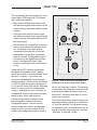
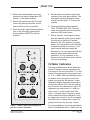
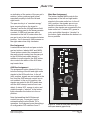
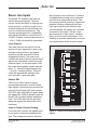
Model 750
Main Output 3
Main Output 3 has been optimized for
connection to devices located external
to the vehicle. This “ruggedized,” transformer-coupled stereo output is selectable, using a front-panel button, for
microphone or line level. It is recommended that Main Output 3 be wired, via
points on the patch bay, to the vehicle’s
input/output connector panel. Two 3-pin
male XLR-type connectors are used for
interconnection. Prepare the mating connectors (females) so that pin 2 is high
(+ or hot), pin 3 is low (– or cold), and pin
1 is shield.
Main Output 3 was specifically designed
to provide a fully-isolated output with good
sonic performance. It was NOT designed
to drive full level into 600 ohm loads! While
a 600 ohm load can be connected without
damage, a 2dB level drop should be
expected. Used with 2k ohm or greater
loads, Main Output 3 will provide its full
specified performance.
AUX Output
A stereo output is provided to give access
to the Model 750’s AUX audio bus. It is
intended that the AUX audio output will be
connected to devices within the vehicle.
The electronically-balanced, line-level
outputs have a nominal level of +4dBu,
and are capable of driving balanced or
unbalanced loads of 600 ohms or greater.
Two ¼-inch 3-conductor phone jacks
used for interconnection. Prepare the
mating connectors (plugs) so that tip
is signal high (+ or hot), ring is low (– or
cold), and sleeve is shield. To connect to
an unbalanced load connect the tip to
high (+ or hot), and both the ring and
sleeve to shield.
Model 750 User Guide
Studio Technologies, Inc.
Even if there are no immediate plans
to connect the AUX audio outputs to
external devices, it is recommended that
they be terminated on patch points. In this
manner they will be accessible for those
“one-in-a-million” situations that seem to
arise far too frequently!
Configurable Outputs
Each of the four configurable outputs is
electronically balanced, has a nominal
level of +4dBu, and is capable of driving
balanced or unbalanced loads of 600
ohms or greater. The outputs are intended
to be used only within the vehicle. DIP
switches are associated with each
configurable output. Details on using
these switches can be found in the Configuration section of this guide.
Each of the configurable outputs is accessible via a ¼-inch 3-conductor phone jack.
Prepare the mating connectors (plugs) so
that tip is signal high (+ or hot), ring is low
(– or cold), and sleeve is shield. To connect to an unbalanced load connect the
tip to high (+ or hot), and both the ring
and sleeve to shield.
It is highly recommended that the configurable outputs be routed via the patch
bay. Or, if there are no immediate needs
for these outputs, be certain to terminate
them on the patch bay for future use.
Sometime, somewhere, they will get used.
Setup Direct Output
Direct access to the setup section’s voice
and tone signals is provided by means of
a stereo line-level output. As one of the
unique features of the Model 750, it should
definitely be utilized! This output is intended to be connected to the audio input
associated with the video/audio switcher’s
Issue 3, May 1997
Page 13
Model 750
“bars and tone” position. For maximum
flexibility, it is recommended that these
signals be connected by way of the patch
bay. In this way they can be accessed for
test and calibration purposes.
The electronically-balanced, nominal
+4dBu outputs are accessible via two
¼-inch 3-conductor phone jacks. The
circuitry is capable of driving balanced or
unbalanced loads of 600 ohms or greater.
Prepare the mating connectors (plugs) so
that tip is signal high (+ or hot), ring is low
(– or cold), and sleeve is shield. To connect to an unbalanced load connect the tip
to high (+ or hot), and both the ring and
sleeve to shield.
Two trim potentiometers are used to set
the output level of the setup direct output.
Refer to the Configuration section of this
guide for details.
External Monitor Inputs
Two external audio signals can be connected, allowing them to be monitored
independently of the internal audio buses.
It is intended that the external monitor
inputs will be connected to outputs associated with off-air, microwave, or satellite
receivers. Both inputs are stereo, electronically balanced, and interface using
¼-inch 3-conductor phone jacks. External
Monitor Input 1 is compatible with signals
that have a nominal level of +4dBu. External Monitor Input 2 is compatible with
–10dBu or +4dBu signals. A DIP switch,
located on the front panel of the Model
750, is used to set the input sensitivity.
Refer to the Configuration section of this
guide for configuration details.
As an installation aid, a connection made
only to the jack labeled L/MONO routes
the signal to both the left and right input
Issue 3, May 1997
Page 14
circuitry. This allows a monaural signal to
be monitored in a 2-channel mono format.
If you wish to have a mono input connected only to the left input, simply insert
an unterminated plug into the associated
right input jack. This will break the “normal” connections that link the left and right
input circuits.
Prepare the mating connectors (plugs)
so that tip is signal high (+ or hot), ring is
low (– or cold), and sleeve is shield. With
an unbalanced source connect the tip to
high (+ or hot), and both the ring and
sleeve to shield. If connecting to an unbalanced source in this manner results in
hum or noise, connect tip to high (+ or
hot) and ring to shield; leave the sleeve
unterminated.
Monitor Output
The monitor output is designed for connection to an audio power amplifier associated with a pair of monitor loudspeakers.
In mobile applications it may prove common for loudspeakers with internal amplifiers, such as those from Fostex, to be
connected to the Model 750’s speaker
output. The outputs are electronicallybalanced, line-level, and can drive balanced or unbalanced loads of 600 ohms
or greater.
The monitor output utilizes two ¼-inch
3-conductor phone jacks for interconnection. Prepare the mating connectors
(plugs) so that tip is signal high (+ or hot),
ring is low (– or cold), and sleeve is shield.
To connect to an unbalanced load connect the tip to high (+ or hot), and both
the ring and sleeve to shield. Whether
these outputs are wired via the patch bay
will depend on the specific installation.
Model 750 User Guide
Studio Technologies, Inc.
Model 750
Record/Talk Back External
Audio Input
The Model 750 contains an internal microphone which is used by the setup section
for voice recording, as well as by the talk
back functions. In special cases it may be
desirable for an external source of audio
to be used in its place. A ¼-inch 3-conductor phone jack allows the connection
of a line-level signal, with a nominal level
range of –20 to +4dBu.
Prepare the mating connector (plug) so
that tip is signal high (+ or hot), ring is low
(– or cold), and sleeve is shield. With an
unbalanced source connect the tip to high
(+ or hot), and both the ring and sleeve
to shield. If connecting to an unbalanced
source in this manner results in hum or
noise, connect tip to high (+ or hot)
and ring to shield; leave the sleeve
unterminated.
It is intended that a microphone associated with an intercom system headset will
serve as the external audio source. Intercom station’s often provide an amplified,
line-level version of the mic signal. It is
often referred to as a “hot microphone”
output.
A trim potentiometer is associated with the
external audio input, allowing adjustment
of the input sensitivity. Refer to the Configuration section of this guide for details.
Information is also provided on how to set
the front panel DIP switch to select the
external audio input.
Connecting AC Mains Power
The Model 750 is factory configured to
operate from AC mains power of either
100, 120, or 220/240V, 50/60Hz. In most
cases, units shipped to North America
are factory configured for 120V operation
and are supplied with an internal 0.5A,
5 x 20mm fast-acting fuse. Units configured for 100V also utilize a 0.5A fuse. Units
configured for 220/240V operation are
supplied with a 0.25A, 5 x 20mm fastacting fuse.
Before connecting the Model 750 to mains
power, determine the actual mains voltage
and confirm that the Model 750 has been
configured correctly. As could be expected, an incorrect mains configuration
could seriously damage the unit.
Figure 4. Detail of back panel showing voltage
configuration chart
Model 750 User Guide
Studio Technologies, Inc.
Should it be necessary to change the
unit’s operating voltage refer to the Service Guide, a separate document available
upon request from Studio Technologies.
Issue 3, May 1997
Page 15
Model 750
The Model 750 uses an IEC standard
connector to mate with the AC mains cord.
Normally the cord supplied has a NorthAmerican standard plug on one end and
an IEC connector on the other. In nonNorth American applications the appropriate plug must be attached. The wire colors
in the mains cord will, in most cases,
conform to the internationally recognized
CEE color code and should be wired
accordingly:
Connection
Wire Color
Neutral (N)
Live (L)
Earth/Ground (E)
Light Blue
Brown
Green/Yellow
outputs is deciding which audio source, or
sources, should be assigned to which
output! By carefully reviewing the choices,
and how their selection may benefit an
installation, the power of this humble output should become apparent. These four
outputs may well eliminate the need for
external distribution amplifiers, combining
amplifiers, and microphone preamplifiers.
Because the Model 750 contains no power
switch it will start operating as soon as AC
mains power is connected.
Configuration
As in life, power leads to responsibility.
The Model 750 is no exception as its
features, flexibility, and operational power
leads to a number of configuration issues
that must be reviewed once installation
has been completed. All are quite simple
and, with the exception of the front panel
configuration DIP switches, will only need
to be addressed once.
Configurable Outputs
The Model 750 contains four configurable
outputs, the likes of which aren’t found on
other audio mixers. Their uniqueness may
make them seem a bit confusing at first
glance. However, they aren’t too weird,
simply being electronically-balanced
output circuits whose input source is
selectable, rather than being fixed. The
hardest part of using the configurable
Issue 3, May 1997
Page 16
Figure 5. Detail of back panel showing
configurable output section (typical of 4)
Model 750 User Guide
Studio Technologies, Inc.
Model 750
The five choices are main output left, main
output right, AUX output left, AUX output
right, and mic/line direct:
• Main output left and main output right
are the same signals that connect to the
output circuitry associated with the main
outputs.
• AUX output left and AUX output right
are the same signals that connect to the
output circuitry associated with the AUX
line-level output.
• Mic/line direct is a signal that is derived
from its associated mic/line input channel. The signal is the same as that
connected to the pan-pot; post input
preamplifier, low-cut filter, and phase
reverse function. Configurable output 1
has access to the signal from mic/line
input 1; configurable output 2 has
access to the signal from mic/line input
2; etc.
Using the five DIP switches associated
with each configurable output, simply
select the source or sources desired. Note
the word “sources”—more than one
source can be selected! As an example,
selecting switch 3, AUX out left, and switch
4, AUX out right, will produce a monaural
(L+R) version of the AUX output. Selecting
switch 1, main out left, for configurable
output 1, and switch 2, main out right, for
configurable output 2 will result in another
stereo output, viola, main output 4!
It would be the author’s choice to use
the configurable outputs in this way:
Configurable output 1 set for a mono
version of the main output, configurable
output 2 set for a mono version of AUX
output, and configurable outputs 3 and 4
Model 750 User Guide
Studio Technologies, Inc.
Figure 6. Detail of back panel showing level
adjustment trim pots for setup direct output
set for mic/line direct outputs. Terminating
on the patch bay, these four outputs could
provide quite handy for those “once in a
blue moon” situations that seem to occur
about once a month!
The two mic/line direct outputs may prove
especially helpful, providing two channels
of “mic/line amplifier” for general purpose
or emergency use. In special situations, a
signal of virtually any audio level could be
“bumped” to nominal +4dBu.
Issue 3, May 1997
Page 17
Model 750
Setup Direct Output
The setup direct output is a stereo linelevel output that provides direct access
to the voice and tone signals. Trim potentiometers allow adjustment of the output
level from approximately –2 to +10dBu.
The trim pots are located on the back
panel, directly above the setup direct
output’s ¼-inch phone jacks. At the factory these outputs are loaded with 100k
ohms, and then the trim pots are adjusted
to give an output level of +4dBu.
If the setup direct output is to be used in
an installation, it’s important that the left
and right channel output levels be adjusted to precisely match the requirements
of the system. Even if you simply want to
use the standard output level of +4dBu,
it’s still important to confirm the factory
calibration. Also note that while the output
circuitry is capable of driving loads of 600
ohms or greater, the output level will drop
slightly as the load impedance approaches 600 ohms. A 0.5dB difference in
output level can be expected as the load
impedance changes from 20k ohms to
600 ohms.
In practice, calibrating the output level
is quite simple:
1. Confirm that both the left and right
channels of the setup direct output
are terminated with their normal load
impedance.
2. Ensure that the Model 750 is connected to mains power.
3. Activate the setup section’s single tone
output by placing the single tone
button to the on (in) position. The voice
and multi-tone buttons should be in
their off (out) position.
Issue 3, May 1997
Page 18
4. Using an appropriate adapter cable,
connect an audio level meter directly
across the left channel setup direct
output. Ensure that your connection
does not remove the normal load! The
level meter must be a precision device
that’s intended for audio use—a
general-purpose voltmeter is not
adequate!
5. Carefully observing the level meter,
adjust the trim pot associated with the
left channel to give the desired output
level.
6. Repeat steps 4 and 5, this time for the
right channel.
External Record/TB Audio
Source
During installation, an external source of
audio may have been connected to serve
in lieu of the Model 750’s internal microphone. This audio source will be used for
voice recording by the setup section, as
well as by the talk back functions. The
external audio source needs to have a
nominal audio level of –20 to +4dBu. A
trim potentiometer, located on the back
panel directly above the record/TB external audio input jack, adjusts the input
sensitivity of the circuitry. For correct
operation it is crucial that this trim pot be
adjusted so that the source audio level is
“matched” with the requirements of the
Model 750.
The procedure is a bit convoluted, but not
difficult:
1. Ensure that mains power is connected
to the Model 750.
Model 750 User Guide
Studio Technologies, Inc.
Model 750
2. Select the external audio source by
placing front panel configuration DIP
switch 1 to the down position.
3. Select the main bus as the VU meter
source by placing the meter source
select button to the out position.
4. Place the main output limiter/compressors to the off state by placing the
button labeled LIMITER to the out
position.
5. Set the main bus master output level
controls to the unity gain position. The
front panel contains a graphic arrow
symbol and the letter “U” to serve as
a guide.
6. Press and hold the button labeled
TALK TO MAIN AND AUX. This connects the external audio source to the
main and AUX audio buses.
7. With a “normal” voice signal coming
from the external audio source, adjust
the trim pot so that the VU meters
deflect to the 0 VU position on signal
peaks. You may want to enlist the help
of another person to serve as a “live”
audio source while you make the
adjustment. It is very important that the
external audio level reflect normal
operation—if your operators or producers love to yell and scream, set the
trim pot accordingly.
VU Meter Calibration
Two trim potentiometers allow calibration
of the VU meter’s normal operating level.
The range of the trim pots allow “0” on the
meters to represent an output signal level
of –2 to +10dBu. While providing a powerful feature, these trim pots must be adjusted very carefully. Be warned—meter
calibration effects the audio performance
of the entire Model 750! From the factory,
the VU meters are calibrated so that 0 VU
represents an output level of +4dBu on
main output 1, when loaded with 100k
ohms. In certain cases it may be a good
idea to check the meter calibration, such
as when main outputs 1 and 2 are loaded
with 600 ohms, or when main output 3 is
going to serve as the “primary” output.
Figure 7. Detail of back panel showing trim
pots for VU meter calibration
Model 750 User Guide
Studio Technologies, Inc.
In some installations it may be desirable to
have a level different from +4dBu, such as
Issue 3, May 1997
Page 19
Model 750
0dBu, to serve as the “0” reference. While
Studio Technologies is not excited about
such a prospect, it can certainly be
achieved. There is one serious downside
to changing the nominal operating level;
the limiter/compressor threshold. The
limiter/compressors are designed to
activate at approximately 6dB above the
Model 750’s internal operating level,
corresponding to an output level of
+10dBu. The threshold is not factory
calibrated and is not easily modified in the
field. If, as an example, the meters are recalibrated for a nominal output level of
0dBu, the limiter/compressors will now
activate at 10dB above this new nominal
level. Prior to changing the operating level,
a discussion with personnel at the factory
may be warranted. Call us for a chat!
While not difficult, meter calibration is a bit
tedious:
1. Ensure that mains power is connected
to the Model 750.
2. Place the main output limiter/compressors to the off state by placing the
button labeled LIMITER to the out
position.
3. Activate the setup section’s single tone
output by placing the single tone
button to the on (in) position. The voice
and multi-tone buttons should be in
their off (out) position.
4. On the setup section, place the main
bus assignment button to the on (in)
position.
5. Select the main bus as the VU meter
source by placing the meter source
button to the monitor (in) position and
selecting main stereo. This makes the
meters most accurate when they are
Issue 3, May 1997
Page 20
monitoring the main bus via the monitor section. If you wish to have the
meters most accurate when they are
connected directly to the main bus, set
the meter source button to the main
(out) position.
6. Designate main output 1, 2, or, in
rare circumstances, 3 as the desired
“primary” output. This is the output that
the meters will be calibrated against. If
main output 3 is selected, set its output
level button to the line (in) position.
7. Confirm that the left and right channels
of the designated main output are
terminated with their normal load
impedance.
8. Using an appropriate adapter cable,
connect an audio level meter directly
across the left channel of the designated main output. Ensure that the
meter connection does not remove the
normal load. The level meter must be a
precision device that’s intended for
audio use—a general-purpose voltmeter is not adequate!
9. Carefully observing the audio level
meter, set the main bus left channel
master output control so that the output level matches the desired nominal
operating level. In most cases this will
be +4dBu.
10. Observing the Model 750’s left channel
VU meter, adjust the left channel meter
trim pot to give 0 VU.
11. Repeat steps 8 through 10, this time
for the right channel.
Model 750 User Guide
Studio Technologies, Inc.
Model 750
tion DIP switches. One is shipped with
each Model 750, being attached to the
front panel by means of two screws.
Where the Model 750 is physically located,
and who will be operating the unit, will
dictate whether the security cover remains
in place or is permanently removed. In a
facility where many operators have access
to the unit, it may be best to set the configuration DIP switches to match the needs
of most operators, then replace the cover.
In a facility where only a few operators
have access, such as an SNG vehicle, the
cover can stay off to allow quick access to
the features.
A brief description of the function of each
configuration DIP switch is contained on
the front panel, directly above the DIP
switches. A more detailed description is
provided here:
Figure 8. Detail of front panel showing
configuration DIP switches
Configuration DIP Switches
Studio Technologies is sorry to report that
the 8 configuration DIP switches had to be
placed on the front panel. We tried to
place them on the back panel where
they’d be hard to reach, or inside the unit
where you’d never find them, but we just
couldn’t find the space—just kidding! The
8 configuration DIP switches are located
on the front panel where you can easily
get at them. These switches allow important operating parameters to be easily
configured, and then quickly changed
“on-the-fly” as operating requirements
dictate. The factory default is to have all
8 switches set to the up position.
A clear plastic “security” cover can be
used to prevent access to the configuraModel 750 User Guide
Studio Technologies, Inc.
1. REC/TB AUDIO SOURCE: EXT ▼ / INT ▲
This switch selects which audio source will be
used by the voice record and talk back sections.
In the down position the external audio source is
selected. In the up position the internal microphone will be used.
Be careful with this switch! In most cases an
external audio source will not be connected and
the internal microphone needs to be selected for
use. It’s easy to accidentally set DIP switch 1 to
the down position and have no source of record
and talk back audio.
2. REC L+R: DISABLE ▼ / ENABLE ▲
This switch selects whether the setup section’s
L+R voice segment can be recorded. In the down
position recording cannot take place. In the up
position recording can take place.
This feature can prove useful where a “semipermanent” L+R voice segment needs to be recorded. By placing the switch to the down
position, the L+R voice segment cannot be
changed.
Issue 3, May 1997
Page 21
Model 750
3. REC L ONLY/R ONLY: DISABLE ▼ / ENABLE ▲
This switch selects whether the setup section’s
L Only and R Only voice segments can be recorded. In the down position recording cannot
take place. In the up position recording can take
place.
This feature can prove useful where “semipermanent” L Only and R Only voice segments
need to be recorded. By placing the switch to the
down position, the L+R voice segment cannot be
changed.
output. Also, if the VU meter source button is set
to follow the monitor section, the AUX bus signals
will automatically be connected to the VU meters
whenever AUX interrupt is active.
8. EXT 2 INPUT LEVEL: –10 ▼ / +4 ▲
This switch is used to select the nominal input
level of external monitor input 2. In the down
position the nominal input level is –10dBu. In the
up position the nominal input level is +4dBu.
4. SINGLE TONE: 400HZ ▼ / 1KHZ ▲
This switch selects whether the setup section’s
single tone feature will generate a 400Hz or a
1kHz sine wave signal. In the down position
400Hz will be generated. In the up position 1kHz
will be generated.
5: MULTI-TONE SEQUENCE: BASIC ▼ /
ADVANCED ▲
This switch selects whether the setup section’s
multi-tone feature will generate a basic or an
advanced sequence of tones. In the down position
the basic sequence will be generated. In the up
position the advanced sequence will be generated. Refer to appendices A-1 and A-2 for detailed
descriptions of the tone sequences.
6: AUX INT SPEAKER: NO ▼ / YES ▲
This switch selects whether the AUX audio bus will
automatically be selected as the audio source for
the monitor speaker whenever an input channel or
the setup section is assigned to the AUX bus. In
the down position a signal assigned to the AUX
bus will not impact the monitor speaker output. In
the up position any signal assigned to the AUX
bus will automatically be connected to the monitor
speaker output. Also, if the VU meter source
button is set to follow the monitor section, the AUX
bus signals will automatically be connected to the
VU meters whenever AUX interrupt is active.
7. AUX INT PHONES: NO ▼ / YES ▲
This switch selects whether the AUX audio bus will
automatically be selected as the audio source for
the headphone output whenever an input channel
or the setup section is assigned to the AUX bus.
In the down position a signal assigned to the AUX
bus will not impact the headphone output. In the
up position any signal assigned to the AUX bus
will automatically be connected to the headphone
Issue 3, May 1997
Page 22
Figure 9. Detail of front panel showing mic/
line input channel (typical of 4)
Model 750 User Guide
Studio Technologies, Inc.
Model 750
Operation
While the Model 750 Audio Mixer is quite
simple to operate, there are nuances to its
design that make a detailed discussion
worthwhile. While you can certainly consider the Model 750 a “small” audio mixer,
its roots are from the much larger audio
consoles that are used in broadcast and
recording settings. We’ll start with a discussion of the individual sections that
make up the Model 750. Then we’ll review
how the sections work together to become
your audio “master control.”
Mic/Line Inputs
Four identical input channels are provided,
each being compatible with a microphone
or line-level signal. A detailed description
of one mic/line channel follows:
Input Sensitivity
The mic/line button is used to select the
sensitivity of the input circuitry. In the mic
(out) position, the expected nominal input
level is –55 to –35dBu. In the line (in)
position, a 40dB pad is inserted into the
circuit, making the expected nominal input
level –15 to +5dBu. The input circuitry is
compatible with a wide range of signal
levels and is protected from overload. In
most cases, an input signal whose nominal level is outside the expected range
shouldn’t pose a problem.
Phantom Power
The button labeled +48V is used to activate “phantom power” for use with condenser-type microphones. The +48V
power supply and related circuitry was
carefully designed to allow virtually any
microphone that requires phantom power
to operate correctly. When the button is in
Model 750 User Guide
Studio Technologies, Inc.
the off (out) position, power is not applied
to the mic/line input connector. When the
button is in the on (in) position, and the
mic/line button is in the mic (out) position,
+48Vdc is applied to the input connector.
When the mic/line button is set for mic,
and a condenser microphone is connected, changing the phantom power
on/off status may result in loud “pops”
being generated. As such, it is best not
to change the position of the +48V button
while its associated input is “live” or
“on-air.”
While it is a good idea to leave the +48V
button in the off position except when
phantom power is required, no damage
should occur to dynamic or ribbon microphones when they’re connected to the
input with phantom voltage present.
(Wow, that’s why they call it “phantom
power”—if a device doesn’t require power
it doesn’t “see” it!)
Low-Cut Filter
The button associated with the “bent line”
graphic symbol is used to select the lowcut filter function. (If you are a stickler for
semantics, it’s actually a high-pass filter
function!) In the off (out) position the filter
is not placed in the audio path, leaving the
signal essentially “flat.” In the on (in)
position the signal is routed through the
filter circuit, removing low-frequency
energy.
The filter is useful for eliminating wind
noise, traffic rumble, and AC mains hum. It
was carefully designed to give a steep
slope (18dB/octave), with the –3dB point
at 85Hz. For most voice applications the
filter can be left activated. For wide-bandwidth signals, such as music, the filter
should be used only as necessary.
Issue 3, May 1997
Page 23
Model 750
Changing the on/off status of the low-cut
filter will result in little or no noise being
added to the audio signal. While it is better
to set the filter’s button to the desired
position prior to being “live,” it can certainly be used at any time.
Phase Reverse
The button associated with the “circlewith-a-slash” graphic symbol is used to
select the phase reverse function. (Many
people will know this as, and is technically, a polarity invert or polarity reverse
function.) In the normal (out) position, the
mic or line input signal maintains the same
polarity from input all the way through to
the main and AUX audio buses. In the
reverse (in) position, the signal is inverted
by 180 degrees. Changing from normal to
reverse, or vice-versa, will generally result
in little or no audio “clicks” or “pops,”
being generated, allowing the function to
be used during “on-air” situations.
This function can be useful in situations
where multiple microphones are present,
and signal cancellation problems occur.
The cancellation can be caused by miswired interconnecting cables, faulty equipment, or acoustic conditions related to
microphone placement. As signal cancellation is not a trivial subject, we recommend that you consult one of the many
fine audio textbooks that are available.
We’ll leave it to you to use the function as
required.
Status LED
A bi-color LED acts as a user-confidence
indication of the overall signal level in the
mic/line input channel’s circuitry. The LED
will light with the color green as a signal
present indicator, showing that the input
signal, along with the gain of the input
Issue 3, May 1997
Page 24
preamplifier, is at least 18dB below the
nominal internal operating level. The LED
will light with the color red as a peak
signal indicator, showing that the input
signal, along with gain of the preamplifier,
is within 6dB of the circuitry’s maximum
level.
Rotary Controls
To address space considerations, the two
rotary controls associated with each mic/
line input channel share the same front
panel space; they’re known as “concentric
pots.” The inner control allows adjustment
of the preamplifier gain, the outer acts as
a “pan-pot.”
Level Control
The inner control is labeled LEVEL, and is
used to adjust the gain of the input preamplifier circuit. In the fully counterclockwise
position the preamplifier gain is set to its
minimum, and full attenuation is achieved.
This means that no signal continues on to
the next stage of the mic/line input circuitry
and, if configured, to the configurable
output on the back panel. As the level
control is rotated in the clockwise direction
the gain of the preamplifier increases.
Pan Pot
The outer control is labeled PAN, and
serves as a pan pot (panorama potentiometer), controlling the routing of the mic/line
signal to the left and right channels of the
main and AUX audio buses. (Of course
the bus assignment buttons must be in the
on (in) position for the signal to actually be
connected to the buses.)
When the pan pot is in the fully counterclockwise position, signal is sent only to
the left mix buses; fully clockwise only to
the right. A mechanical “detent” provides
Model 750 User Guide
Studio Technologies, Inc.
Model 750
an indication of the center of the pan pot’s
rotation. In this position signal is sent
essentially equally to both the left and
right buses.
The pan circuitry is a “constant-energy”
type, ensuring that as the signal is
“panned” across the left/right stereo field,
the total energy sent to the buses remains
constant. A 3dB level increase will be
observed on the left VU meter when the
pan pot is set to the fully counterclockwise
position. You’ll observe a 3dB increase on
the right meter when fully clockwise.
Main Bus Assignment
The button labeled MAIN controls the
assignment of the left and right audio
signals to the main audio bus. In the off
(out) position, the signals are not connected to the main bus; in the on (in)
position, the signals are connected to the
main audio bus. A status LED, green in
color and visible through a “window” in
the button, lights whenever the button is in
the on position.
Bus Assignment
Located below the level and pan controls
are two buttons, labeled AUX and MAIN.
These buttons control the connection of
the audio signal coming from the pan pot
to the AUX and main audio buses. In
addition to audio signals, the AUX button
also controls the status of the AUX interrupt control bus.
AUX Bus Assignment
The assignment button labeled AUX controls the routing of the left and right audio
signals to the AUX audio bus. In the off
(out) position, signals are not routed to the
bus, and the AUX interrupt control bus is
not enabled. In the on (in) position, the
signals are routed to the AUX audio bus,
and the AUX interrupt control bus is enabled. A status LED, orange in color and
visible through a “window” in the button,
lights whenever the button is in the on
position.
Note that enabling the AUX interrupt
control bus may, or may not, have a
noticeable effect on the Model 750’s
operation. It will depend upon the settings
of configuration DIP switches 6 and 7.
Model 750 User Guide
Studio Technologies, Inc.
Figure 10. Detail of front panel showing stereo
line input channel (typical of 2)
Issue 3, May 1997
Page 25
Model 750
Stereo Line Inputs
The Model 750 contains two identical
stereo line input channels. They are
unique, having the ability to support true
stereo sources, as well as single or twochannel monaural sources that are common to broadcast environments. The
circuitry was designed for compatibility
with signals that have a nominal level of
+4dBu. However, nominal signal levels of
–10 to +10dBu are perfectly acceptable.
input signals to be routed and, if desired,
combined before being sent to the main
and AUX bus assignment buttons. The
four routing buttons provide a unique and
powerful function, allowing the left and
right input signals to be routed in any
manner desired, not simply the “left input
connects to left output” and the “right
input connects to right output” situation
that is found in most audio mixers. This
flexibility is provided specifically for broadcast applications where a source signal
Level Controls
Two level controls are used to set the
amount of input signal that is sent to the
left/right routing buttons, and subsequently on to the main and AUX bus
assignment buttons. The inner knob
controls the level of the left channel input
signal; the outer knob controls the right
channel signal. On the front panel, note
the small arrow graphic symbol and the
letter “U,” located at approximately the
“1-o’clock” rotation position. This indicates the approximate setting for the
level controls to give unity gain.
Status LEDs
Two bi-color LEDs serve as signal
present/peak indicators for the left and
right signals. Electrically they monitor the
output of the left and right level controls.
The LEDs light with the color green when
the signals are 18dB or greater below the
Model 750’s nominal internal operating
level. The LEDs light with the red color
when the signals are within 6dB of the
maximum.
Input-to-Output Channel Routing
From the level controls, the signals pass
to two pairs of channel assignment buttons. The assignment buttons allow the
Issue 3, May 1997
Page 26
Figure 11. Detail of front panel showing setup
section
Model 750 User Guide
Studio Technologies, Inc.
Model 750
may consist of a “true” stereo signal, a
dual-channel monaural signal, or one or
two independent monaural signals.
Associated with the left channel input are
two buttons, labeled OUT L and OUT R.
When both buttons are in the off (out)
position, the left input signal can’t be
connected to the left or right output bus.
(The final connection to the buses actually
occurs by means of the bus assignment
buttons.) Placing the OUT L button in the
on (in) position allows the left input signal
to be connected to the left output buses;
OUT R allows the left input to be connected to the right output buses. Placing
both buttons to the on (in) position allows
the left input signal to be connected to
both the left and right output buses. Two
buttons are associated with the right
channel input and function in the same
manner.
The number of routing possibilities may
seem almost endless but you math
experts know there are actually only 16!
If you spend a bit of time thinking about
the routing you’ll see how a variety of
stereo and monaural inputs can be routed
and combined to create virtually any
desired stereo or monaural output.
Bus Assignment
Signals from the left/right assignment
buttons are sent to the main and AUX bus
assignment buttons. These two buttons
operate in the same fashion as described
for the mic/line input channels. The main
button assigns the line input signals to the
main bus. The AUX button assigns the line
input signals to the AUX mix bus and
enables the AUX interrupt control bus.
Model 750 User Guide
Studio Technologies, Inc.
Setup Functions
The Model 750’s setup section will be a
“new animal” to most operators, but is
really quite simple and intuitive to understand and use. (The simple and intuitive
part will become more obviously after you
read the following section!)
The setup section allows the recording
and playback of voice identification signals, along with the generation of sinewave audio tones.
Setup Direct Output and Bus
Assignment
A separate stereo output is provided on
the back panel, giving direct access to
the voice and tone signals generated by
the setup section. Whenever one of the
setup section’s voice identification or tone
functions is active, the signal generated
will always appear on the setup direct
output. Only if the bus assignment buttons
are activated will the setup signals be
connected to the main and AUX audio
buses. This allows the buses to continue
to be used for normal audio signals, even
while voice identification or sine-wave
tones are being generated. What a concept—your entire audio mixer doesn’t
have to be “tied-up” so you can generate
a 1kHz tone for some geek at a TV station
in North Dakota. (The author is living
dangerously—he has family in Minot!)
Voice Recording
Three push-button switches allow you to
record custom voice identification messages; 12 seconds maximum for the L+R
segment, 4 seconds maximum each for
the L Only and R Only segments. One
status LED, red in color, is associated with
the three record buttons. The LED will light
Issue 3, May 1997
Page 27
Model 750
steadily when recording is taking place,
flashing on and off during the final 2 seconds of recording time. To ensure that an
existing recording will not accidentally be
erased, you must press and hold a record
button for 2 seconds before recording will
begin. You must continue to press the
button during the entire time you want to
record, releasing the button only when
you want to stop recording.
Should you attempt to record longer than
the maximum allowable time, recording
will automatically stop, as evidenced by
the record status LED turning off, and the
monitor speaker output “un-muting.” Only
by releasing the record button, then pressing and holding it for 2 seconds will recording begin again. Once you have completed recording you needn’t worry about
“losing” the information—the memory
circuitry will hold it for at least 10 years!
You should be aware that the ultimate
ability to record voice segments is controlled by means of configuration DIP
switches 2 and 3, located on the lower
right corner of the front panel. Switch 2
enables and disables the recording of the
L+R segment; switch 3 applies to both the
L Only and R Only segments. Recording
will not take place if a function is disabled,
no matter how long you press and hold its
button!
There may be special cases where you
don’t want to record and playback all
three voice segments, wanting only one or
two of them to be active. To facilitate this
an “erase” function is provided. A voice
segment is “erased” by pressing and
holding its associated record button until
recording begins, as evidenced by the
record LED lighting, then immediately
releasing the button. Technically, the
Issue 3, May 1997
Page 28
software that controls the setup section
interprets any recording of less than 1
second as an erase indication. During
playback, a voice segment that has been
erased will be skipped.
An operational example may be useful:
Once upon a time a Model 750 was used
to “split feed” two separate news networks. The L Only segment was used to
convey information relevant to network 1,
and the R Only segment was used to
convey information specific to network 2.
A message recorded on the L+R segment
was not desired, as it would have been
sent to both networks. So the L+R segment was erased by pressing and holding
the record L+R button until recording
began, and then the button was released
immediately. The desired messages were
recorded onto the L Only and R Only
segments, which were the only ones that
played back. The “live shot” went so
smoothly that the field technician was
promoted, moved to New York City, and
is now earning those big bucks!
The audio source for the recording is
either the internal microphone, located
between and a little above the VU meters,
or an externally-connected source. Configuration DIP switch 1 selects which
source is active.
Experience will teach you how to achieve
the best record audio quality. While convenient, the front panel microphone is prone
to noise pickup. Speaking closely into the
front-panel microphone will result in the
best signal-to-noise ratio. An external
audio source, such as an amplified signal
coming from a noise-canceling headset,
will lead to a more “high-fi” recording.
Model 750 User Guide
Studio Technologies, Inc.
Model 750
Be Warned! The easiest means of getting
a very quiet recording is to have DIP
switch 1 set to EXT, while having no external audio signal connected! (During initial
testing of the Model 750 the guys in Studio
Technologies’ lab did this more than once,
causing high-SPL howls of “what happened—the recording section doesn’t
work anymore.”)
To keep other audio signals from interfering with the record audio, the Model 750’s
monitor speaker output is automatically
muted whenever recording is taking place.
(During initial testing, it was found that this
muting feature was also very useful in an
unintended way; providing an audible
“marker” as to when to begin talking.)
Using the Play Functions
Three buttons are associated with the
setup section’s play functions. Adjacent to
each button is an LED indicator that lights
whenever its respective function is active.
The uniqueness of the setup section is
highlighted by the use of blue LEDs, a
rarity that we think adds a bit of “coolness” to the Model 750!
It is important to understand the operating
differences between when only one of the
play buttons has be set to the on (in)
position, and when more than one has
been set to the on position. When only
one button has been selected, the function
associated with that button will operate
continuously. When more than one button
has been selected, the selected functions
will alternate according to a pre-programmed schedule.
Remember, the setup section has a direct
audio output. This means that any time
one of the play functions is active, an
audio signal will be present on the setup
Model 750 User Guide
Studio Technologies, Inc.
direct output. The active audio signal will
only be connected to the main and/or AUX
buses if their respective bus assignment
buttons are enabled. In the following
paragraphs it is assumed that these buttons have be set to their desired positions.
Voice Play
If the button labeled VOICE is the only one
selected, playback of the L+R, L Only,
and R Only voice segments will occur in
a continuous sequence. The L+R voice
segment will play first, connecting the
recorded audio to both the left and right
channels. After a 1-second pause, the L
Only voice segment will connect to the left
channel, with silence on the right channel.
After another 1-second pause, the R Only
voice segment will connect to the right
channel, with silence on the left channel.
After a 2-second pause the L+R voice
segment will again play. And so it goes
If a voice segment has been electronically
marked as erased, it will be skipped from
the playback sequence. If all three segments have been “erased,” then the voice
play status LED will flash in a 1-secondon/1-second-off cadence whenever the
play function is enabled.
Single Tone Play
If the button labeled SINGLE TONE is the
only one selected, a continuous 400Hz or
1kHz sine-wave signal will be connected
to both the left and right channels. Configuration DIP switch 4 is used to select
whether 400Hz or 1kHz will be generated.
Multi-Tone Play
If the button labeled MULTI-TONE is
the only one selected, a pre-configured
sequence of sine-wave signals will play
continuously, each complete sequence
Issue 3, May 1997
Page 29
Model 750
being separated by a 2-second pause.
Each sequence provides tones for checking frequency response, as well as left/
right channel identifiers. Configuration DIP
switch 5 is used to select whether the
basic or advanced multi-tone sequence
will be generated. Refer to Appendices
A-1 and A-2 for detailed descriptions of
the multi-tone sequences.
Multiple Play Functions
When more than one play button is selected, a different set of rules apply. If the
voice button is selected, along with the
single tone and/or multi-tone button(s),
the voice sequence of L+R, L ONLY, and
R ONLY will play once, a 2-second pause
will occur, and then the next selected
function will become active.
If the single tone button has been selected, along with the voice and/or multitone button(s), a 400Hz or 1kHz tone will
be generated for 15 seconds, a 2-second
pause will occur, and then the next function will become active.
If the multi-tone button has been selected,
along with the voice and/or single tone
button(s), one complete basic or advanced multi-tone sequence will be generated, and then, after a 2-second pause,
the next function will become active. To
know which function is active is simply
a matter of observing the play LED
indicators.
Master Output
The Model 750’s master output section
contains a variety of buttons and controls
associated with the main and AUX audio
buses.
Issue 3, May 1997
Page 30
Figure 12. Detail of front panel showing
master output section
AUX and Main Master Level Controls
Two controls are used to set the overall
level of the AUX audio bus. The inner knob
controls the level of the left channel; the
outer knob controls the right channel. On
the front panel, note the small arrow
graphic symbol and the letter “U,” located
at the “1-o’clock” rotation position. This
indicates the approximate setting for the
level controls to give unity gain, and is the
position where the controls should normally be set.
Model 750 User Guide
Studio Technologies, Inc.
Model 750
Another two controls are used to set the
overall level of the main audio bus. They
too should be set to the unity gain position
except in special situations.
Limiter/Compressors
A studio-quality limiter/compressor circuit
is associated with each channel of the
main audio bus. A push-button switch
selects the off/on status; when the button
is in the out position the limiter/compressors are not active. When the button is in
the on (in) position, high signal levels on
the main audio bus will be automatically
attenuated.
Two green LEDs display the operating
status of the limiter/compressors. They
light whenever signal attenuation is taking
place. Note that the limiter/compressor
circuits operate independently for the left
and right channels—they do not “track”
together.
Main Outputs
Three stereo output connections are provided on the back panel, providing access
to the signals on the main audio bus. Main
outputs 1 and 2 are configured for line
level. A button, located on the front panel,
selects the output level for main output 3.
Setting the button to the out position selects microphone level; the in position
selects line level.
Talk Back
Two buttons allow voice signals to be
connected to the setup direct output and
the main and AUX output buses, creating
a “talk back” function for cueing, slating,
and setup use. The talk back audio source
is the same as that used by the setup section’s voice recording function. Depending
on the setting of configuration DIP switch
1, it is either the internal microphone or an
externally-connected line-level audio
source. The Model 750’s monitor speaker
output is automatically muted whenever a
talk back function is active.
Pressing and holding the talk back button
labeled SETUP DIRECT OUT connects the
voice audio source to the setup direct
output connections. The voice audio
signal will be added (summed) with whatever signal is also present on the setup
direct output; a voice or tone signal
present on the setup direct output will not
be muted while talk back is taking place.
Pressing and holding the talk back button
labeled MAIN & AUX OUT connects the
voice audio source to the main and AUX
audio buses. The voice audio signal will
be added (summed) with whatever signals
are also present on the buses.
Monitor Section
Figure 13. Detail of front panel showing
monitor section
Model 750 User Guide
Studio Technologies, Inc.
The monitor section assists the operator in
obtaining the best performance from the
Model 750. It controls the signals that are
presented to the VU meters and associated peak indicator lights, speaker output,
Issue 3, May 1997
Page 31
Model 750
and headphone output. Acting as a trusty
assistant, the monitor section allows visual
and aural monitoring of a variety of signals, without effecting the main and AUX
audio buses. Understanding and becoming comfortable with using the monitor
section is crucial to obtaining optimal
Model 750 performance.
Source Selection Buttons
The core of the monitor section are the six
monitor source buttons. The six buttons
allow one or more of the audio sources to
be selected for monitoring. A review of the
sources may prove helpful:
• Main—Stereo This selects the left and
right channels of the main audio bus as
the monitor source; left channel is
routed to the left channel of the monitor
section, right channel to the right channel. This selection is appropriate when
stereo program audio is present on the
main bus, or when independent signals
present on the left and right channels of
the main bus need to be simultaneously
monitored.
• Main—Left This selects the left channel
of the main audio bus as the monitor
source. The left channel is routed to
both the left and right channels of the
monitor section. This allows a singlechannel monaural program feed, or the
left channel of a two-channel “splitfeed,” to be monitored. (An example of
a “split-feed” is where the left channel
of the main bus is handling audio for
network 1, while the right channel of the
main bus is handling audio for network
2.)
• Main—Right This selects the right
channel of the main audio bus as the
monitor source. The right channel is
Issue 3, May 1997
Page 32
routed to both the left and right channels of the monitor section. This allows
a single-channel monaural program
feed, or the right channel of a twochannel “split-feed,” to be monitored.
• AUX This selects the left and right
channels of the AUX audio bus as the
monitor source; left channel is routed to
the left channel of the monitor section,
right channel to the right channel. This
selection is appropriate when stereo
program audio is present on the AUX
bus, or when independent signals
present on the left and right channels of
the AUX bus need to be simultaneously
monitored.
• EXT 1 This button selects external
monitor input 1 as the monitor source;
left input channel is routed to the left
channel of the monitor section, right
channel to the right channel. If the
external source is monaural, and has
been connected only to the jack labeled
L/MONO, the signal will automatically
be routed to both the left and right
monitor channels. This allows a monaural signal to be monitored over both the
left and right channels, a method that,
while really 2-channel monaural (binaural), is comfortable and reassuring for
many people.
• EXT 2 This button selects external
monitor input 2 as the monitor source.
It’s similar to EXT 1, with the exception
that its input level sensitivity is configurable using configuration DIP switch 8.
Should you find the level of EXT 2 to be
significantly louder or softer when
compared to the other monitor sources,
configuration DIP switch 8 should be
checked.
Model 750 User Guide
Studio Technologies, Inc.
Model 750
The monitor source push-button switches
were chosen to allow more than one
source to be selected at a time. The ability
to simultaneously depress and lock multiple buttons is not a “glitch,” but is a feature which can prove useful in some
specialized situations. An example is where
a “mix-minus” cue signal from a remotelylocated facility is being returned to the
Model 750 by means of external monitor
input 1. By selecting both EXT 1 and main
stereo, a composite signal is created for
monitoring.
Monaural Function
A function is provided that allows the selected monitor source to be combined to
form a monaural signal. The monaural function is useful for checking a stereo audio
signal’s “image” across the left/right field,
as well as determining its monaural compatibility. When the stereo/mono button is
in the mono (in) position, the left and right
channels of the monitor source are combined (summed) and the level of the summed signal is dropped by 6dB. The 6dB
level reduction is a standard part of the
monaural function on virtually all audio
consoles, preventing level buildup caused
by the summing of phase coherent signals.
The monaural function does not impact the
main and AUX audio buses, affecting only
the monitor speaker output, headphone
output, and the meters. Note that the
monaural function effects the monitor
source selected by the push-button
switches, as well as, if configured and
active, the AUX interrupt signal.
Metering
Two VU-type meters and associated LEDs
are provided for visual level monitoring.
The meters provide the operator with an
Model 750 User Guide
Studio Technologies, Inc.
excellent sense of the average signal level,
while the LEDs display peak signal conditions. A “peak” LED lights whenever the
level of the signal being monitored
reaches within 6dB of the maximum internal bus level. In the “real world,” audio
material with large transient information
may only display a moderate signal level
on the VU meters. While the fast response
time of the peak LEDs will allow the presence of such transients to be displayed.
A push-button switch, located at the top
of the monitor section, allows the audio
source for the meters to be selected.
When the button is in the main (out) position the left channel of the main audio bus
is sent to the left meter, the right channel
of the main audio bus is sent to the right
meter. When the button is in the monitor
(in) position the monitor source selected
for the speaker and headphone outputs is
connected to the meters. Reviewing the
ramifications of the meter source button
may prove useful; we do so in the following paragraphs:
Allowing the meters to directly monitor the
main audio bus is provided for operator
peace-of-mind. It allows a continuous
display of what is, in most situations, the
“on-air” audio bus, no matter what is
happening in the monitor section. Note
that when the meter source button is set to
the main (out) position, use of the stereo/
mono button will have no impact on the
meters. Activation of the AUX interrupt
function won’t affect the meters either.
With the meters selected to observe the
monitor source, great flexibility is possible.
However, unless a full understanding of
how the meters function in this mode is
gained, the flexibility can be accompanied
by confusion!
Issue 3, May 1997
Page 33
Model 750
• With the monitor stereo/mono button
set to stereo, and neither the speaker
nor the headphone outputs being
interrupted by the AUX interrupt function, the left channel of the selected
monitor source is connected to the left
meter; the right channel is connected to
the right meter.
• Whenever the speaker output, the
headphone output, or both the speaker
and headphone output are interrupted
using the AUX interrupt function, the
signals on the AUX audio bus are automatically connected to the meters; left
channel to the left meter, right channel
to the right meter.
• When the stereo/mono button is in the
mono (in) position, the left and right
monitor signals, being either the normal
source or AUX interrupt, are added
(summed), attenuated by 6dB, and sent
to both the left and right meters.
Speaker Output
As part of the Model 750’s monitor section, a stereo “speaker” output is provided, along with an associated level
control and status LED indicator. The
speaker output is actually line-level, not
speaker level. It’s designed to be connected to an audio power amplifier and
associated loudspeakers, or “amplified”
speakers that contain internal power
amplifiers.
The signal source for the speaker output
is either the selected monitor source or,
when interrupted by the AUX interrupt
function, the AUX audio bus. If configuration DIP switch 6 is set to the up (on)
position, any signal assigned to the AUX
audio bus will automatically replace the
normal monitor source. The LED labeled
Issue 3, May 1997
Page 34
AUX INT will light, indicating that the normal monitor source is being interrupted by
the AUX signal.
The speaker output is muted whenever a
voice message is being recorded, or one
of the talk back functions is active. The
speaker mute limits the amount of sound
that can get into the microphone, and can
prevent the occurrence of acoustic feedback.
Headphone Output
A separate stereo headphone output is
provided, along with an associated level
control and status LED indicator. The
phones output is designed to work well
with virtually any of the contemporary
medium and high-impedance headphones.
Sony MDR-7056s were used during the
design of the Model 750; their high sensitivity made them go “way loud!” While a bit
“bright” in the high-end for our taste, their
comfort and fine design make them a good
choice for use with the Model 750.
If configuration DIP switch 7 is set to the up
(on) position, any signal assigned to the
AUX audio bus will automatically replace
the normal monitor source. The LED labeled AUX INT will light, indicating that the
normal monitor source is being interrupted
by the AUX signal. Unlike the speaker
output, the phones output is never muted.
Warning: Protect your ears! The
Model 750 is capable of driving headphones to extremely high sound pressure levels. Hearing experts advise
against continuous extended play,
especially at high levels. Polka music
has been found to be especially dangerous, so please be careful.
Model 750 User Guide
Studio Technologies, Inc.
Model 750
Practical Operating Tips
Now that we’ve reviewed all the sections
that comprise the Model 750, it’s time to
actually use the unit. In the following
paragraphs some suggestions about how
to best use the Model 750 are provided.
Setting the Bus Operating Levels
The main and AUX master level controls
allow the overall gain structure of the
audio mixing buses to be set. Correctly
setting these controls ensures that maximum audio quality will be achieved. In
most cases simply setting the controls to
the unity gain position is appropriate; the
unity gain position is clearly marked on
the front panel. If you are a fanatic for
accuracy, you may want set the level
controls “precisely” using the following
procedure:
1. On the setup section, set the single
tone button to the on (in) position. This
will cause a 400Hz or 1kHz steady tone
to be generated.
2. On the setup section, place the main
bus assignment button to the on (in)
position; the AUX bus assignment
button must be in the off (out) position.
3. Set the meter source button to the
monitor (in) position.
4. Set the monitor source button to main
stereo.
5. Adjust the main master level controls
so that the meters “read” 0 VU. The
main bus is now set for precisely unity
gain.
6. On the setup section, place the main
bus assignment button to the off (out)
position and the AUX bus assignment
button to the on (in) position.
Model 750 User Guide
Studio Technologies, Inc.
7. If the AUX interrupt function becomes
active (due to configuration DIP
switches 6 and/or 7 being set to their
on (up) position) the meters are now
monitoring the AUX bus. If the AUX
interrupt function is not active, set the
monitor source to AUX.
8. Adjust the AUX master level controls so
that the meters “read” 0 VU. The AUX
bus is now set for precisely unity gain.
9. The procedure has now been completed. Return the buttons on the setup
and monitor sections to the desired
operating setting.
Signal Present/Peak LEDs
Bi-color status LEDs are provided on the
mic/line and stereo line input sections.
Under normal operating conditions the
LEDs should light only with the color
green. Signal peaks may cause an occasional red flash, but sustained lighting of
the peak indicator means that audio performance is being compromised. Adjust
the level controls so that you aren’t “in
the red” except on rare occasions.
Limiter/Compressors
While the Model 750 was designed to
provides lots of signal “headroom,” most
applications, especially broadcast, won’t
benefit from it. In fact, wide dynamic
range, in many cases, will simply tax the
transmission chain and lead to signal
degradation. Our feeling is that leaving
the limiter/compressor button to the on
(in) state is your best bet. If you can’t think
of a good reason why extended dynamic
range is desired, leave the limiter/compressors active!
Issue 3, May 1997
Page 35
Model 750
Don’t misunderstand our position: Extended dynamic range is great for music
recordings. We love listening to terrific
classical, jazz, and, when available, pop
recordings. But for the applications served
by the Model 750 dynamic range is not
really a factor. Go ahead, prove us wrong
and use the Model 750 to record the
London Symphony Orchestra. Then you
should turn the limiter/compressors off!
Technical Notes
¼-Inch Plugs and EIA RS-453
An incompatibility problem lurks between
some ¼-inch 2-conductor and 3-conductor phone plugs and the jacks found on
professional audio equipment. While all
the plugs seem to “look” the same, some
do not comply with the industry standard,
called EIA RS-453. This standard defines
the physical dimensions, including the
shape of the plug’s tip. It seems that some
plug manufacturers don’t bother to make
the tip comply with the standard.
Why is this relevant to you? Because the
phone jacks used on the Model 750 do
comply with the standard, and they expect
to be mated with plugs that do, too.
Should a connection seem “flaky,” sound
noisy, or make intermittent contact, the
most likely problem is a nonstandard
phone plug. Replace the plug if this is the
case.
You should find that all plugs from Switchcraft or Neutrik will work correctly, specifically Switchcraft No. 297 or Neutrik NP3C.
In our experience, headphones are the
most likely place to find nonstandard
plugs—we even found them on some
“world-class” headphones that we use
in our lab!
Issue 3, May 1997
Page 36
Definition of Level
Studio Technologies has opted to use
the dBu designation as it seems to be
quite rational. Using dBm was fine when
all audio outputs were terminated with 600
ohm loads. In this way it was easy to say
that “0dB” was 1 milliwatt dissipated in the
known load (i.e., 0dBm across 600 ohms
will measure 0.775V). Today, an output is
rarely terminated with 600 ohms; generally
10k ohms or higher. The dBu designation
is better because it refers to dB referenced
to 0.775V, with load impedance not a
factor. This takes into account the contemporary audio scene where most equipment has a low output source impedance,
and a high input impedance.
External Monitor Input 2
This section is buried here because we
are almost certain that no one in management will ever read this far into the guide!
Sources connected to the external monitor
inputs will usually have a nominal level of
+4dBu, so why the –10/+4 DIP switch for
input 2? Frankly, we thought that field
engineers may sometimes want to connect a piece of –10 “consumer” audio
gear for their own “personal monitoring.”
While operating a remote vehicle can be
challenging and fast-paced, it can often be
filled with hours of waiting. The ability to
connect a compact disk player or cassette
“Walkman” may make the time pass a little
more pleasantly!
You might recognize that we selected
–10dBu, even though the –10 designation
usually implies –10dBV. We feel that
–10dBu is a better sensitivity when connecting to “–10” equipment. As –10dBV =
–7.78dBu, the extra 2.22dB of sensitivity is
helpful.
Model 750 User Guide
Studio Technologies, Inc.
Model 750
Faux VU Meters
In the spirit of George Washington (and
to make our mother proud of us) we have
to “tell the truth” and admit that while the
meters selected for the Model 750 are of
very good quality, they don’t meet the
specifications of a “true” VU meter. So
why was a less-than-perfect meter selected for the Model 750? The answer is
easy and not surprising. While the Model
750’s existing meter is already quite expensive, being built in England by a topnotch meter manufacturer, the cost for
a “true” VU meter is about five times as
much!
be precisely calibrated when the meter
source button is set to the main (out)
position. (In this position the main audio
bus is directly connected to the meters.)
A difference of up to 0.5dB from the calibrated value could be expected. This is
due to tolerance variations in the components of the monitor circuitry. In reality,
only when a steady tone is present on the
main audio bus will this variation become
apparent. During actual operation it unlikely to become a factor.
The technical difference between the
meter used on the Model 750 and a “true”
VU meter lies in the ballistic characteristics, i.e. how the pointer accelerates and
decelerates in response to audio signals.
The Model 750’s meter pointer moves very
close to, but not exactly in the manner
required to be “perfect.”
For the Model 750 operator, the selected
meter provides a completely acceptable
indication of level. But as a technicallyoriented company, we wanted to “come
clean” about our actions. Too bad so
many other audio companies don’t tell
you that their “VU meters” are fakes—
many don’t even come close to meeting
the specs!
VU Meter Calibration
From the factory the VU meters are calibrated so that a +4dBu signal level, as
measured on main output 1, results in a
reading of 0 VU on the meters. (The meter
source button is set to the monitor (in)
position and the source is selected to
be main stereo.) However, it may be
observed that the meters may no longer
Model 750 User Guide
Studio Technologies, Inc.
Issue 3, May 1997
Page 37
Model 750
Specifications
General Audio Parameters:
Frequency Response: 20Hz-20kHz, ±0.5dB,
stereo line in/main out 1
Distortion (THD+N): 0.04%, measured at 1kHz,
mic in/main out 3
S/N Ratio: 80dB, referenced to +4dBu, mic in/
main out 3
Connectors:
Mic/Line, Stereo Line: 3-pin XLR-type, female
(pin 2 high)
Main Out 3: 3-pin XLR-type, male (pin 2 high)
All Other Audio: ¼-inch 3-conductor phone jacks
AC Mains: 3-blade IEC-type
Mic/Line Inputs: 4
Main Audio Bus Limiter/Compressor: 2
Type: single-knee, VCA-controlled, non-tracking
Threshold: +10dBu, nominal (6dB above
nominal output level)
Attack Time: 2mSec, nominal
Release Time: 100mSec, nominal
Slope: 5:1, nominal
Status LED: 2, limiter/compressor active
Outputs — Main 1, Main 2, AUX, Configurable,
and Setup Direct:
Type: electronically balanced, capacitor-coupled,
intended to drive balanced or unbalanced loads
of 600 ohms or greater
Source Impedance: 50 ohms, nominal
Nominal Level: +4dBu (Setup Direct Output
adjustable, range –2 to +10dBu)
Type: balanced, transformer-coupled
Maximum Level: +27dBu into 10k ohms,
+26dBu into 600 ohms
Impedance: mic 1k ohms, line 9k ohms
Main Output 3:
Common Mode Rejection Ratio: 68dB @ 60Hz
(typical)
Type: balanced, transformer-coupled, intended to
drive balanced or unbalanced loads of 2k ohms
or greater
Level Range:
Mic: –70 to –10dBu; Line: –30 to +30dBu
Range specified to give +4dBu output level,
master level controls set to unity gain position
Source Impedance: mic 200 ohms, line 170
ohms, nominal
Microphone Power: +48V phantom-type
Nominal Level: mic –36dBu, line +4dBu,
selectable
Low-Cut Filter: –3dB at 85Hz, 18dB/octave slope
Maximum Level: +21dBu into 10k ohms
Status LED: bi-color, signal present/peak
Monitor Output:
Pan Type: constant energy
Pan Attenuation: 60dB, nominal
Stereo Line Inputs: 2
Type: electronically balanced, direct-coupled,
compatible with balanced or unbalanced signals
Impedance: 24k ohms
Common Mode Rejection Ratio: 100dB @ DC
and 60Hz, 70dB @ 20kHz, 62dB @ 40kHz, typical
Nominal Level: +4dBu (–8 to +10dBu
acceptable)
Status LED: 2, bi-color, signal present/peak
Type: electronically balanced, capacitor-coupled,
intended to drive balanced or unbalanced loads
of 600 ohms or greater
Source Impedance: 50 ohms, nominal
Nominal Level: –2dBu, with monitor level control
@ 100%
Maximum Level: +21dBu into 10k ohms,
+20dBu into 600 ohms
Headphone Output:
Compatibility: intended for connection to headphones with impedance of 100 ohms or greater
Maximum Voltage: 8Vpp, 100 ohm load
Issue 3, May 1997
Page 38
Model 750 User Guide
Studio Technologies, Inc.
Model 750
External Monitor Inputs: 2, stereo
AC Mains Requirement:
Type: electronically balanced, direct-coupled,
compatible with balanced or unbalanced signals
100, 120, or 220/240V, ±10%, factory configured;
50/60Hz; 40 watts maximum
Impedance: 24k ohms
Dimensions (Overall):
Common Mode Rejection Ratio: 100dB @ DC
and 60Hz, 70dB @ 20kHz, 62dB @ 40kHz, typical
Nominal Level, Input 1: +4dBu
Nominal Level, Input 2: –10 or +4dBu,
selectable
Setup Section:
Record L+R Duration: 12 seconds, maximum
Record L Only, R Only Duration: 4 seconds,
maximum
Record Audio Source: internal microphone or
external line level, selectable
Single Tone Frequency: 400Hz or 1kHz,
selectable
19.00 inches wide (48.3cm)
3.49 inches high (8.9cm)
9.50 inches deep (21.4cm)
Mounting:
2 standard rack spaces
Weight:
14.0 pounds (6.4kg)
Specifications subject to change without notice.
Basic Multi-Tone Frequencies: 1kHz reference,
followed by 10kHz, 1kHz, 100Hz
Advanced Multi-Tone Frequencies: 1kHz
reference, followed by 14 tones (15kHz-50Hz)
Setup Direct Output Level: +4dBu, nominal,
adjustable, range –2 to +10dBu
Status LEDs: 4
Talk Back:
Connects voice audio source to setup direct and/
or main and AUX outputs
Record/Talk Back External Audio Input:
Type: electronically balanced, capacitor-coupled,
compatible with balanced or unbalanced signals
Level Range: –20 to +4dBu, adjustable
Metering: 2
Type: analog panel, VU scale, with signal peak
LED
Calibration: 0 VU = +4dBu, nominal, adjustable,
range –2 to +10dBu
Peak LED: lights at 6dB below internal bus clip
level
Illumination: 14 LEDs (7 per meter)
Polarity:
Input-to-output polarity maintained, except
inversion on headphone output
Model 750 User Guide
Studio Technologies, Inc.
Issue 3, May 1997
Page 39
Model 750
Appendix A-1. Basic Multi-Tone Sequence
Time Interval
Issue 3, May 1997
Page 40
Left Channel
Right Channel
Seconds
Frequency (Hz)
Frequency (Hz)
4
1000
1000
1
Silence
Silence
2
10000
10000
1
Silence
Silence
2
1000
1000
1
Silence
Silence
2
100
100
1
Silence
Silence
500mSec
700
Silence
1
Silence
Silence
500mSec
Silence
700
1
Silence
Silence
500mSec
Silence
700
2
Silence
Silence
Model 750 User Guide
Studio Technologies, Inc.
Model 750
Appendix A-2. Advanced Multi-Tone Sequence
Time Interval
Left Channel
Right Channel
Seconds
Frequency (Hz)
Frequency (Hz)
4
1000
1000
1
Silence
Silence
2
15000
15000
1
Silence
Silence
2
12500
12500
1
Silence
Silence
2
10000
10000
1
Silence
Silence
2
8000
8000
1
Silence
Silence
2
6000
6000
1
Silence
Silence
2
4000
4000
1
Silence
Silence
2
2000
2000
1
Silence
Silence
2
1000
1000
1
Silence
Silence
2
700
700
1
Silence
Silence
2
500
500
1
Silence
Silence
2
400
400
1
Silence
Silence
2
250
250
1
Silence
Silence
2
100
100
1
Silence
Silence
2
50
50
1
Silence
Silence
500mSec
700
Silence
1
Silence
Silence
500mSec
Silence
700
1
Silence
Silence
500mSec
Silence
700
2
Silence
Silence
Model 750 User Guide
Studio Technologies, Inc.
Issue 3, May 1997
Page 41