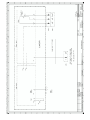
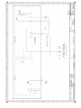
1
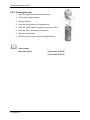
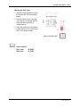
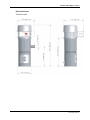
Operating Instructions
Machine-Side Hopper Loader
SSE Series
Machine-Side Hopper Loaders
Machine-Side Hopper Loaders
Sterling Material Processing
5200 West Clinton Ave.
Milwaukee, WI 53223
Telephone: (414) 354-0970
Fax: (414) 354-6421
www.sterlco.com
Technical service:
Service department
Telephone: (800) 423-3183
Edition: 03/04
Bulletin #: SM4-615.2
These operating instructions are for*:
(* please fill in personally)
Serial number:
Year of manufature:
Date of Delivery:
Number of delivery:
Date of commissioning:
Location:
Group of machines:
ii
Machine-Side Hopper Loaders
Sterling Material Processing retains all rights to change the information in these
operating instructions at any time without notice.
We assume no liability for any errors or direct or indirect damage resulting in context
with these operating instructions.
Copying, translation or publication in any form except for personal use of purchaser
requires approval from Sterling Material Processing.
All rights reserved.
iii
Machine-Side Hopper Loaders
iv
Please note that our address and phone information has changed.
Please reference this page for updated contact information.
These manuals are obsolete and are provided only for their technical information, data and capacities.
Portions of these manuals detailing procedures or precautions in the operation, inspection, maintenance
and repair of the products may be inadequate, inaccurate, and/or incomplete and shouldn’t be relied
upon. Please contact the ACS Group for more current information about these manuals and their
warnings and precautions.
Parts and Service Department
The ACS Customer Service Group will provide your company with genuine OEM quality parts manufactured to engineering
design specifications, which will maximize your equipment’s performance and efficiency. To assist in expediting your phone
or fax order, please have the model and serial number of your unit when you contact us. A customer replacement parts list
is included in this manual for your convenience. ACS welcomes inquiries on all your parts needs and is dedicated to
providing excellent customer service.
For immediate assistance, please contact:
•
North, Central and South America, 8am – 5pm CST +1 (800) 483-3919 for drying, conveying, heating and cooling
and automation. For size reduction: +1 (800) 229-2919.
North America, emergencies after 5pm CST (847) 439-5855
North America email: [email protected]
•
Mexico, Central & South America
Email: [email protected]
•
Europe, Middle East & Africa +48 22 390 9720
Email: [email protected]
•
India +91 21 35329112
Email: [email protected]
•
Asia/Australia +86 512 8717 1919
Email: [email protected]
Sales and Contracting Department
Our products are sold by a worldwide network of independent sales representatives. Contact our Sales Department for the
name of the sales representative nearest you.
Let us install your system. The Contract Department offers any or all of these services: project planning; system packages
including drawings; equipment, labor, and construction materials; and union or non-union installations.
For assistance with your sales or system contracting needs please Call:
North, Central and South America +1 (262) 641-8600 or +1 (847) 273-7700 Monday–Friday, 8am–5pm CST
Europe/Middle East/Africa +48 22 390 9720
India +91 21 35329112
Asia/Australia +86 512 8717 1919
Facilities:
ACS offers facilities around the world to service you no matter where you are located. For more information, please visit us at
www.acscorporate.com
United States:
ACS Schaumburg – Corporate Offices
1100 E. Woodfield Road
Suite 588
Schaumburg, IL 60173
Phone: + 1 847 273 7700
Fax: + 1 847 273 7804
ACS New Berlin – Manufacturing Facility
th
2900 S. 160 Street
New Berlin, WI 53151
Phone : +1 262 641 8600
Fax: + 1 262 641 8653
Asia/Australia:
ACS Suzhou
109 Xingpu Road SIP
Suzhou, China 215126
Phone: + 86 8717 1919
Fax: +86 512 8717 1916
Europe/Middle East/Africa:
ACS Warsaw
Ul. Działkowa 115
02-234 Warszawa
Phone: + 48 22 390 9720
Fax: +48 22 390 9724
India
ACS India
Gat No. 191/1, Sandbhor Complex
Mhalunge, Chakan, Tal Khed,
Dist. Pune 410501, India
Phone: +91 21 35329112
Fax: + 91 20 40147576
Machine-Side Hopper Loaders
Table of Contents
1. General instructions......................................................................................................... 1-1
1.1. Warnings and symbols ......................................................................................................................... 1-2
1.2. Explanations and information .............................................................................................................. 1-3
1.3. Legal basis ............................................................................................................................................ 1-3
1.4. Fields of applications............................................................................................................................ 1-3
1.5. Notes on usage...................................................................................................................................... 1-3
2. Safety instructions ........................................................................................................... 2-1
2.1. For your safety...................................................................................................................................... 2-2
2.1.1. General......................................................................................................................................... 2-2
2.1.2. Assembly....................................................................................................................................... 2-3
2.1.3. Operation ..................................................................................................................................... 2-4
2.1.4. Maintenance................................................................................................................................. 2-4
2.2. For the operating safety of the equipment ........................................................................................... 2-5
3. Transport, assembly and storage .................................................................................... 3-1
3.1. Transport and packing .......................................................................................................................... 3-2
3.2. Assembly .............................................................................................................................................. 3-2
3.3. Storage .................................................................................................................................................. 3-2
4. Assembly instructions...................................................................................................... 4-1
4.1. Unpacking............................................................................................................................................. 4-2
4.2. Installing the dump valve sensor.......................................................................................................... 4-3
4.3. Attaching the pickup wand................................................................................................................... 4-4
4.4. Mounting............................................................................................................................................... 4-5
4.4.1. Mounting on the processing machine ......................................................................................... 4-6
4.4.2. Mounting onto a machine hopper ............................................................................................... 4-6
4.4.3. Mounting onto mixing hoppers with lateral inlet ....................................................................... 4-7
4.4.4. Mounting onto DT 30 dosing station .......................................................................................... 4-7
4.5. Electrical connection ............................................................................................................................ 4-8
4.6. Compressed air connection .................................................................................................................. 4-8
4.7. Installation of the optional proportioning valve .................................................................................. 4-9
5. Functional description ..................................................................................................... 5-1
5.1. Sequence of operation .......................................................................................................................... 5-2
5.2. Controller .............................................................................................................................................. 5-2
6. Operation ......................................................................................................................... 6-1
6.1. Switching on the unit............................................................................................................................ 6-2
6.2. Checking the flexible hose ................................................................................................................... 6-2
6.3. Setting the conveying time................................................................................................................... 6-3
6.4. Setting the purge time (optional) ......................................................................................................... 6-4
6.5. Initial operation..................................................................................................................................... 6-5
6.6. Switching off the unit ........................................................................................................................... 6-5
7. Troubleshooting ............................................................................................................... 7-1
7.1. Alarms................................................................................................................................................... 7-2
v
Machine-Side Hopper Loaders
8. Maintenance..................................................................................................................... 8-1
8.1. Maintenance intervals........................................................................................................................... 8-3
8.2. Servicing the loader.............................................................................................................................. 8-4
Changing the sealing ring of the outlet flap........................................................................................... 8-4
8.2.2. Adjusting the dump valve sensor................................................................................................. 8-5
8.2.3. Cleaning the unit.......................................................................................................................... 8-6
8.2.4. Replacing carbon brushes at the motor ...................................................................................... 8-8
8.3. Taking out of service, dismantling, disposal ..................................................................................... 8-10
8.3.1. General....................................................................................................................................... 8-10
8.3.2. Disposal Instructions................................................................................................................. 8-10
9. Technical data.................................................................................................................. 9-1
10. Spare parts list ............................................................................................................... 10-1
10.1. Parts breakdown, brush-type motor ................................................................................................. 10-2
10.2. Parts lists, 2-liter model.................................................................................................................... 10-3
10.2.1.
230 V, 50 Hz........................................................................................................................ 10-3
10.2.2.
110 V, 60 Hz........................................................................................................................ 10-4
10.2.3.
230 V, 50 Hz with active cleaning...................................................................................... 10-5
10.2.4.
110 V, 60 Hz with active cleaning...................................................................................... 10-5
10.3. Parts list, 5-liter model ..................................................................................................................... 10-6
10.3.1.
230 V, 50 Hz (V66372, V66363)......................................................................................... 10-6
10.3.2.
110 V, 60 Hz (V66378US) .................................................................................................. 10-7
10.3.3.
230 V, 50 Hz with active cleaning (V66364) ..................................................................... 10-8
10.3.4.
110 V, 60 Hz with active cleaning...................................................................................... 10-8
10.4. Parts breakdown and list, 5-liter model with brushless motor........................................................ 10-9
10.5. 230 V, 50 Hz................................................................................................................................... 10-10
11. Accessories ..................................................................................................................... 11-1
12. Electrical manual ........................................................................................................... 12-1
vi
Machine-Side Hopper Loaders
1. General instructions
M
These instructions apply to all persons within the range of action of the
equipment.
These operating instructions are to be used by all persons assigned activities
connected with the equipment.
General instructions 1-1
Machine-Side Hopper Loaders
1.1. Warnings and symbols
The following warnings and symbols are used in these operating instructions:
M
L
F
&
$
This symbol indicates danger to life. Fatal or serious injury is possible if the
corresponding instructions, regulations or warnings are not observed.
This symbol indicates that serious injury is possible if the corresponding
instructions, regulations or warnings are not observed.
This symbol indicates that extensive damage to equipment is possible if the
corresponding instructions, regulations or warnings are not observed.
This symbol indicates information important for becoming familiar with the
equipment, i.e. technical correlations.
This symbol indicates that a technical term is explained at this point.
1-2 General instructions
Machine-Side Hopper Loaders
1.2. Explanations and information
Various terms are used in these operating instructions to ensure clarity. Therefore
please note that the terms used in the text stand for the corresponding explanations
listed below.
• Equipment: ”Equipment” can mean an individual unit, a machine or an installation.
•
Operating personnel: The ”operating personnel” are persons operating the
equipment on their own responsibility or according to instructions.
•
Operator: The ”operator” of the equipment (production manager, foreman, etc.) is the
person responsible for all production sequences. The operator instructs the operating
personnel of what is to be done.
•
Operating instructions: The ”operating instructions” describe the interaction of the
equipment, production sequences or methods. The operating instructions must be
compiled by the operator of the equipment.
•
Equipment foreman: When several operating personnel work on one machine, the
”equipment foreman” coordinates the sequences. The equipment foreman must be
appointed by the operator.
•
Trained personnel: ”Trained personnel” are persons who, due to their training, are
authorized to carry out the required work.
1.3. Legal basis
See “Manufacturer’s Certificate” resp. “Certificate of Conformity”.
1.4. Fields of applications
These machine-side hopper loaders are designed for use in facilities that require
independent machine conveying systems. The loaders have been developed for
conveying thermoplastic granules. A typical area of application is for processing
machines and drying hoppers with throughputs of up to 400 lbs./hr (180 kg/h).
1.5. Notes on usage
•
Experienced operators can begin directly with the chapter on “Start-up” if the unit has
been properly installed.
•
If the unit has not been installed yet, observe the instructions in the chapters
“Transport, Assembly and Storage” and “Assembly Instructions”.
General instructions 1-3
Machine-Side Hopper Loaders
2. Safety instructions
M
These safety instructions apply to all persons within the range of action of the
equipment, and should be used by all persons assigned activities connected
with the equipment.
Please inform all persons within the range of action of the equipment of the
direct and indirect hazards connected with the equipment.
Knowledge of the English language is prerequisite.
Ensure that all operating personnel are familiar with the operating instructions
and the function of the equipment.
Safety instructions 2-1
Machine-Side Hopper Loaders
2.1. For your safety
2.1.1. General
To prevent injury and/or damage to equipment, observe the following safety rules:
•
Read these operating instructions carefully before operating for the first time. Contact
us should questions arise.
•
These operating instructions must be kept available at all times at the place of
operation of the equipment.
•
Please note that, for reasons of clarity, not all conceivable cases regarding operation
or maintenance of the equipment can be covered in these operating instructions.
•
Observe all safety instructions and warnings on the equipment.
•
All work on the equipment is to be carried out by persons whose qualifications are
specified in the pertaining chapters of the operating instructions.
•
Wear proper working clothes while performing any work on the equipment.
•
The local regulations and requirements pertaining to this equipment must be
observed.
•
Disconnect electrical components from the main power supply before work is carried
out on these components
•
Compile detailed operating instructions based on these operating instructions for the
sequence of procedures to be carried out on this equipment.
•
Please note that sound levels exceeding 85 db(A) may in the long term damage your
health. Use appropriate ear protection to prevent hearing impairment.
2-2 Safety instructions
Machine-Side Hopper Loaders
2.1.2. Assembly
To prevent injury and/or damage to equipment, observe the following safety rules:
•
Compare the connected loads with those of the main supply.
•
Use care when using lifting gear, and observe any pertaining regulations.
•
Do not modify, add other equipment or change the design of the equipment without
the approval of the manufacturer.
•
Attachments not supplied by the manufacturer must be manufactured in accordance
with safety regulation EN 294.
•
Make sure all the accessories and components are properly connected in
accordance with any relevant regulations.
•
To prevent electrical shock, operate the device only if all its components are
grounded.
•
Do not allow solid particles and dust to enter to the vacuum generator.
Safety instructions 2-3
Machine-Side Hopper Loaders
2.1.3. Operation
To prevent injury and/or damage to equipment, observe the following safety rules:
•
Appoint an equipment foreman to be responsible for the equipment.
•
Ensure that the operating personnel are provided detailed instruction in the operation
of the equipment.
•
When the main switch is switched off for reasons pertaining to safety, it must be
secured against unauthorized activation.
•
Repair work may be carried out by trained personnel only.
•
Never operate the equipment when partially dismantled.
•
In case of malfunction, shut down the equipment immediately. Have malfunctions
corrected immediately.
•
The equipment is intended only for conveying granulated plastics and regrinds. Any
other or additional use is contrary to specifications.
•
This equipment is not suitable for food processing.
•
The safety instructions of the connected machines must be followed.
•
Explosive gases and mixtures of gas and air must not be conveyed.
2.1.4. Maintenance
To prevent injury and/or damage to equipment, observe the following safety rules:
•
Before starting maintenance work, appoint a supervisor.
•
Inform the responsible personnel before maintenance work on the system is started.
•
Disconnect the equipment from main supply before starting maintenance procedures
to ensure that it cannot be switched on unintentionally.
•
All pipes, hoses and screwed connections should be checked regularly for leaks and
damage. Any faults that arise should be corrected immediately.
•
Depressurize all compressed air piping before starting maintenance work.
2-4 Safety instructions
Machine-Side Hopper Loaders
2.2. For the operating safety of the equipment
Never change settings if the consequences are not precisely known.
Use only original manufacturer-approved spare parts.
Please observe the maintenance schedule.
Keep record of all maintenance and repair work.
Please note that electronic components may be damaged by static discharge.
Check all electrical connections for proper fit before the equipment operated for the first
time and at regular intervals.
The operating temperature range is 32 to +113 °F (0 °C to +45 °C).
The recommended storage temperature range is -13 to +131 °F (-25 °C and +55 °C).
Write down all data that you have entered into the control system.
Please ensure that all plugs are correctly plugged in.
The operating instructions of the connected machines must be followed.
Operate the device only if all its components are grounded.
Never adjust sensors without exact knowledge of their function.
Please note that a compressed air supply is required for the operation of the active
cleaning option.
Compressed air supply for the active cleaning option should not exceed 87 PSI (6 bar)
(active cleaning option only).
Align the suction tubes correctly.
The unit should be installed in such a way that the outlet flap swings at right angles to
the moving direction of the equipment.
The load-bearing capacity of the machine flange should be adhered to.
A level indicator is required when conveying from granulators.
Safety instructions 2-5
Machine-Side Hopper Loaders
3. Transport, assembly and storage
M
This chapter is intended for all operating personnel of the equipment.
Personnel using these instructions must be instructed in the regulations for
the prevention of accidents, the operating conditions and safety regulations
and their implementation.
Ensure in each case that the operating personnel are sufficiently informed.
Please inform all persons within the range of action of the equipment of the
direct and indirect hazards connected with the equipment.
Please observe all safety regulations for the operation of lifting equipment.
Transport, assembly and storage 3-1
Machine-Side Hopper Loaders
3.1. Transport and packing
M
Please ensure adequate carrying capacity of the lifting equipment.
The equipment passes rigorous testing in the factory and is packed carefully to avoid
transport damage.
Please check packing on delivery for transport damage.
The inlet and discharge flanges are sealed with plugs, so that no dirt can enter during
transport. Plugs must be removed before assembly.
Packing materials should be disposed of according to environmental laws or reused.
Only use for transport of the equipment a suitable lifting device (e. g. a fork lift truck or a
workshop crane).
Transport must be shock-proofed and free from vibrations.
3.2. Assembly
M
Please ensure adequate carrying capacity of the lifting equipment.
Check the carrying capacity of the point of installation, particularly if installed
on a platform.
The place selected for installation should be as free of vibrations as possible.
The main power switch must be freely accessible.
Ground the equipment against electrostatic charging.
3.3. Storage
The control system may only be stored at temperatures from -13 to +131 °F (-25 to
+55°C).
Between delivery and machine commissioning, the equipment should be stored in a dry,
dust-free and vibration-free room.
3-2 Transport, assembly and storage
Machine-Side Hopper Loaders
4. Assembly instructions
M
These installation instructions are intended for persons with skills in electrical
and mechanical areas due to their training, experience and received
instructions.
Personnel using these installation instructions must be instructed in the
regulations for the prevention of accidents, the operating conditions and
safety regulations and their implementation.
Ensure in each case that the personnel are sufficiently knowledgeable about
the equipment.
The installation instructions provided in the corresponding operating
instructions apply for all connected equipment.
Please observe all safety regulations for the operation of lifting gear.
All installation work must be carried out with the equipment disconnected from
electrical power and compressed air supply.
L
For installation work taking place at heights of over approx. 6 feet, use only
ladders or similar equipment and working platforms intended for this purpose.
At greater heights, the proper equipment for protection against falling must be
used.
Use only suitable lifting gear that is in proper working order and load
suspension devices with sufficient carrying capacity. Do not stand or work
under suspended loads!
Use only suitable workshop equipment.
F
Install the equipment so that all parts are easily accessible; this facilitates
maintenance and repair work.
Assembly instructions 4-1
Machine-Side Hopper Loaders
4.1. Unpacking
The loader is insensitive to shocks and can be
mounted directly onto the processing machine, on
a machine hopper, a drying hopper or a dosing
and blending unit.
The equipment is delivered as a complete
assembly.
Use the following procedure to prepare the
machine for assembly:
1. Unpack the equipment.
A
2. Remove the plastic stopper (A) from the
material inlet nozzle.
3. Open the access door (B) and remove the
adhesive tape from the dump valve.
F
The controller must be freely accessible.
4-2 Assembly instructions
B
Figure 1: 2-liter model
Machine-Side Hopper Loaders
4.2. Installing the dump valve sensor
The controller uses a dump valve sensor (A) with a
magnet (B) to determine demand. When the dump
valve is closed, indicating demand, the magnet is
pushed towards the sensor. The presence of the
magnet near the sensor indicates demand and
triggers a new conveying cycle.
When the dump valve is open, indicating that no
material is needed, the magnet is pushed up and
away from the sensor. If the sensor does not
detect the magnet, it does not trigger a new
conveying cycle.
B
A
Figure 2: Dump valve and sensor
To install the dump valve sensor, insert the appliance plug of the dump valve sensor into
the connector (Figure 3) on the lower side of the controller.
Figure 3: Lower side of the controller
Assembly instructions 4-3
Machine-Side Hopper Loaders
4.3. Attaching the pickup wand
Use the following procedure to attach the pickup wand:
1. The pickup wand must be connected to flexible hose to allow sufficient movement.
The length of the hose should not exceed 10 feet (3 meters). Push the free pipe end
approximately 1.5” to 2” (4-5 cm) into the hose. Use a hose clamp to secure the
connection. The flex hose should not cover the aeration holes on the pickup wand.
2. Slide the flexible hose onto the material inlet. Use the hose clamps supplied to
secure the flex hose.
The pickup wand needs no adjustment for most applications. Insert it into the material to
be conveyed and turn the loader on. Some applications require a more defined air-tomaterial ratio.
The pickup wand can be angled up to approximately 45 degrees in either direction to the
vertical. Additional fastening is not required.
When conveying from the bottom of storage containers (silos, surge bins, blender bins,
etc.), a suction box is required.
4-4 Assembly instructions
Machine-Side Hopper Loaders
4.4. Mounting
Please check during assembly that the admissible bearing loads are not exceeded.
Mount the loader in such a way that the outlet flap swings in a right angle to the direction
of machine movement.
Please check that all connecting points are tight to ensure that the conveying
performance is not impaired.
Figure 4: Mounting
Assembly instructions 4-5
Machine-Side Hopper Loaders
4.4.1. Mounting on the processing machine
A VT Series adapter is required to mount the
loader on the processing machine. Two-liter
models require a VT 1.0 adapter. Five-liter
models require a VT 2.3/70 or VT 2.8/70
adapter. Use the following procedure to mount
the loader to the processing machine:
1. Mount the VT Series adapter onto the flange
of the processing machine.
Figure 5: VT Adapter
2. Mount the loader onto the adapter.
F
Observe the bearing capacity of the machine flange.
4.4.2. Mounting onto a machine hopper
Two-liter models require an EF 190 welding flange for mounting onto a machine hopper.
Five-liter models can be mounted to a machine hopper using either the EF 253 welding
flange or the MF 253 assembly flange.
Using the EF Series Welding Flange:
L
Please observe all safety regulations for the
operation of welding equipments.
Always wear safety goggles.
Figure 6: EF Welding Flange
1. Weld the welding flange into the machine hopper lid.
2. Mount the loader onto the welding flange.
Using the MF Series Assembly Flange (Five liter models
only)
1. Mount the assembly flange into the machine hopper lid.
2. Mount the loader onto the assembly flange.
4-6 Assembly instructions
Figure 7: MF Assembly Flange
Machine-Side Hopper Loaders
4.4.3. Mounting onto mixing hoppers with lateral inlet
A VT Series adapter is required to mount the
loader on a mixing hopper with a laterial inlet.
Two-liter models require a VT 1.0 adapter. Fiveliter models require a VT 2.3/70 or VT 2.8/70
adapter. Use the following procedure to mount
the loader to the mixing hopper:
1. Mount the adapter onto the swan-neck of
the mixing hopper.
Figure 8: VT Adapter
2. Mount the loader onto the adapter.
F
Observe the bearing capacity of the machine flange.
4.4.4. Mounting onto DT 30 dosing station
Two-liter loaders mount directly onto the DT 30
Dosing Station. Five-liter models require an AD 1/5
adapter.
Two Liter Models:
1. Mount the dosing hopper directly onto the
dosing container of the dosing station DT 30.
2. Mount the loader onto the dosing hopper.
F
Figure 9: DT 30
Observe the bearing capacity of the
machine flange.
Five Liter Models:
1. Mount the adapter piece directly onto the dosing
container of the dosing station DT 30.
2. Mount the loader onto the adapter piece.
F
Figure 10: AD 1/5
Adapter
Observe the bearing capacity of the machine flange.
Assembly instructions 4-7
Machine-Side Hopper Loaders
4.5. Electrical connection
M
The regulations of the local electrical codes must be observed.
Before connection to the electricity supply, ensure that the supply voltage and
the power frequency are in accordance with the data on the nameplate of the
machine.
The electrical connection may only be carried out by the manufacturer’s
service staff or trained personnel authorized by the manufacturer.
It is not permitted for other persons to undertake the electrical connection.
The main switch must be freely accessible.
Ground the equipment against electrostatic charging.
The equipment is connected to main power supply by a standard plug.
Separate fuse protection of the wall socket is required (max. 16 A).
4.6. Compressed air connection
The hopper loader requires a clean, dry, 72-87 psi compressed air supply. A filter,
regulator, and shut-off valve are recommended components of your in-plant air supply.
You may need to install an accumulator in your air supply system to enhance blowback
effectiveness if your system cannot consistently meet these requirements. Make sure
you use full-sized 3/8” diameter pipe or tubing when making the connection.
4-8 Assembly instructions
Machine-Side Hopper Loaders
4.7. Installation of the optional proportioning valve
&
Before proceeding, review the connecting diagram included with the unit.
For more information, refer to the manual that shipped with the proportioning
valve.
Connecting the proportioning valve:
Control and power of the proportioning valve is supplied through a 4-wire control
connection.
Brown
–
Positive Power
X7, L
Blue
–
Negative power
X7, N
Black
–
Line signal
X7, ZKW
Green w/ Yellow
–
Ground
X3
1. Remove the control box face, and locate the removable plug in the bottom of the
box.
2. Remove the plug and feed the wire of the proportioning valve through the empty
hole.
3. Tighten the lock nut inside, position the wire length for optimum use and tighten the
lock nut on the outside.
4. Strip the wires so that 1/4” of wire is showing, for connection to terminal blocks.
5. Upon removal of the loader control face you will see two printed circuit boards. One
board on the reverse of the control face, and the other mounted inside the control
box. The ground wire will connect to the terminal block X3 on the back of the control
face. The other three wires connect to terminal block X7 inside the control box, in
order from left to right Brown, Blue, then Black. Please refer to the schematic in the
back of the manual.
Assembly instructions 4-9
Machine-Side Hopper Loaders
Connecting Material Lines:
Component 1 – connected to the intake port furthest from the air cylinder (regrind)
Component 2 – connected to the intake port closest to the air cylinder (virgin)
Setting the ratio:
When the loader motor is not running, pressing the arrow key on the valve’s controller
will change the percentage of component 1. This can be set from 0% to 99%
Set the cycle switching:
Press and hold the percentage key on the valve’s controller. Then by pressing the up
arrow, you will be selecting the cycle time period in increments of 5 sec.
For example, if the convey time is 60 seconds and you select a cycle time period of 10
sec. the valve will switch a total of 6 times.
4-10 Assembly instructions
Machine-Side Hopper Loaders
5. Functional description
M
This functional description is intended for all operating personnel of the
equipment.
General knowledge of conveying systems is required to operate the equipment
Ensure in each case that the operating personnel are sufficiently
knowledgeable about the equipment.
Functional description 5-1
Machine-Side Hopper Loaders
5.1. Sequence of operation
The sequence of operation is as follows:
1. Plug in the machine and move the on/off switch to the “on” position
2. All LEDs on the controller blink, and the software version is displayed on the screen.
3. A 2-second blowback pulse cleans the filter. During blowback, the screen displays
“A2.”
4. The motor starts, and conveying begins. The screen displays a countdown of the
conveying time. Conveying time can be set for 1-99 seconds.
5. If the optional purge valve is installed, line purging begins, and the screen displays a
countdown of purge time. Purge time can be set for 0-99 seconds.
6. The motor shuts off for 8 seconds while material dumps. The screen displays “L8.”
The 8-second dump time is a fixed setting and is not adjustable.
7. The controller checks for demand, and if material is needed, the cycle starts over
from step 3.
5.2. Controller
3 LEDs indicate the respective modes of operation: blowback, conveying, purging, and
dumping.
Blowback
Conveyin
g
Purging
Dumping
Blowback Icon
Conveying Icon
Purging Icon
Change-over Key
Arrow Key
Figure 11: Controller
5-2 Functional description
Machine-Side Hopper Loaders
6. Operation
M
This chapter is intended for operating personnel.
General knowledge of the operation of conveying systems is required to
perform these tasks. Make sure you have read and understood the Functional
Description chapter in this manual before operating the equipment.
Ensure that all operating personnel are sufficiently knowledgeable about the
equipment.
F
Make sure the plastic stopper has been removed from the material inlet nozzle.
Make sure the adhesive tape has been removed from the exit flap.
Operation 6-1
Machine-Side Hopper Loaders
6.1. Switching on the unit
Locate the power switch on the left side of the control box and switch it to the “on”
position.
6.2. Checking the flexible hose
Before operating the equipment, check to make sure the suction is working:
1. Remove the pickup wand from the flexible hose.
2. Cover the open end of the hose with your hand.
3. Connect the unit to the main power supply and turn the machine on.
a. If the motor is operating, your hand will feel the suction within few seconds.
b. If you don’t feel the vacuum, the flexible hose is not tight.
4. Check the hose and seal any loose points you may have identified.
5. Reconnect the pickup wand.
6-2 Operation
Machine-Side Hopper Loaders
6.3. Setting the conveying time
F
&
Do not overfill the hopper loader
The conveying time cannot be set while the unit is in the process of conveying
material.
By correctly setting the conveying time, you can reduce vacuum motor wear, save
energy, and reduce your need to maintain filters:
1. Turn on the hopper loader
2. Observe the flex hose and the material in which you buried the pickup probe. Listen
to the vacuum motor and the sound that the material makes as it enters the hopper
loader.
3. When the hopper loader is full, the conveying rate drops off sharply. You can
observe this condition in the clear flex hose and the material container in which you
buried the pickup probe. When the hopper loader is full, the vacuum motor and
material sounds also change.
4. Make a note of the elapsed time from the start of conveying to the time the hopper
loader is full.
5. Turn the hopper loader off
6. Disable the conveying cycle by disconnecting the dump valve sensor from the
controller. With the dump valve sensor disabled, no demand will be indicated, and
the conveying cycle will not start.
7. Turn the hopper loader on.
8. Use the arrow key to adjust the conveying time to slightly shorter
than it takes to fill the hopper loader. For example, if the hopper is
full by the 30-second point of the conveying sequence, set the
conveying time to 28 seconds.
NOTE: To decrease the load time setting it is necessary to cycle the time setting past 99 and
then to the desired setting. There is no “down” button.
9. With the new time setting entered, reconnect the dump valve sensor. Conveying
should start again.
&
The conveying time that was last selected appears in the display.
The conveying time can be set at 1 to 99 seconds.
•
If the hopper loader is overfilling, reduce the conveying time.
•
If the hopper loader is not filling to capacity, increase the conveying time.
10. Check operation to ensure proper settings. If settings are not right, repeat steps 1-9.
Operation 6-3
Machine-Side Hopper Loaders
6.4. Setting the purge time (optional)
To set the purge time, press and hold the “change-over” key while using the “arrow key”
to adjust the time.
&
The purge time that was last selected appears
in the display.
The purge time can be set at 1 to 99 seconds.
F
If no line clearing valve has been installed, enter “0".
1. Turn the hopper loader off.
2. Disable the conveying cycle by disconnecting the dump valve sensor from the
controller. With the dump valve sensor disabled, no demand will be indicated, and
the conveying cycle will not start.
3. Turn the hopper loader on.
4. Enter a conveying time setting. (See Section 6.3. on page 6-3.)
5. Enter a purge time. This is done by pressing (and holding) the change-over key (the
bottom and center LED should be lit). Then pressing the arrow key. The purge time
on the display will increase.
6. Reconnect the dump valve sensor. Conveying should start.
7. Verify both the load time and purge time settings. This can be done by observing the
conveying cycle. When the loader motor starts, it will convey material for the time
entered. After this time expires, the motor stays on and the line clearing valve is
activated. At this time, the conveying line will be “purged” clean of material. When
the settings are correct, the load time is just long enough to pull the desired amount
of material into the conveying line and the purge time is just long enough to clean out
the line. Once both of these functions are complete, the material level in the hopper
should be at the material inlet level, but not above. If this is not the case readjust the
settings by repeating steps 1-7.
NOTE: To decrease the load time and purge settings, it is necessary to cycle the time
setting past 99 and then to the desired setting. There is no “down” button.
8. Once the settings are optimized, the loader is ready for operation.
6-4 Operation
Machine-Side Hopper Loaders
6.5. Initial operation
Metal shavings may be inside the pipe from cutting down pipes into lengths. These are
pulled during the first conveying process and collected in the separator.
F
This material should not be used again.
6.6. Switching off the unit
Locate the power switch on the left side of the control box and switch it to the “off”
position.
Operation 6-5
Machine-Side Hopper Loaders
7. Troubleshooting
M
This chapter is intended for the operating personnel of the equipment.
General knowledge of the operation of conveying systems is required to
perform these tasks.
Make sure you have read and understood the “Start-up” section of this manual
before proceeding.
Ensure that the operating personnel are sufficiently knowledgeable about the
equipment.
Troubleshooting 7-1
Machine-Side Hopper Loaders
7.1. Alarms
An alarm will be triggered if there is no material to convey or if the loader overheats.
&
An “E” appears in the display and an error number.
And alarm will sound.
F
Do not restart operation until the malfunction has been corrected.
The following error messages can be displayed:
“E1"
The alarm message “E1" is displayed when no material has been conveyed during 3
consecutive conveying cycles.
• Check that sufficient material is being conveyed.
•
Check that the flap switch is set correctly.
As supplied, this feature is disabled. To enable it:
1. Turn the loader off and remove power.
2. Remove the cover from the control.
3. Remove the two wires that are connected to terminals X9 and X6
4. Replace the cover and turn the loader on.
“E2"
If the control system becomes too hot during operation (>158°F, 70°C) the “E2" alarm
message is displayed and the unit is switched off.
• Allow the system to cool before restarting.
&
When the malfunction has been corrected, turn the power off and then on
again to restart.
7-2 Troubleshooting
Machine-Side Hopper Loaders
8. Maintenance
M
This chapter is intended for persons with skills in electrical and mechanical
areas due to their training, experience and received instructions.
Personnel using the instructions in this chapter must be instructed of the
regulations for the prevention of accidents, the operating conditions and
safety regulations and their implementation.
Ensure in each case that the personnel are sufficiently knowledgeable about
the equipment.
For maintenance work taking place at heights of over approx. 6 feet, use only
ladders or similar equipment and working platforms intended for this purpose.
At greater heights, the proper equipment for protection against falling must be
worn.
Use only suitable lifting gear that is in proper working order and load
suspension devices with sufficient carrying capacity. Do not stand or work
under suspended loads!
Ensure that the electric motors/switch cabinets are sufficiently protected
against moisture.
Use only suitable workshop equipment.
Before starting maintenance work, appoint a supervisor.
Inform the responsible personnel before maintenance work on the system is
started.
Never operate the equipment when partially dismantled.
All maintenance and repair work not described in this chapter may only be
carried out by the manufacturer’s service personnel or authorized personnel
(appointed by the manufacturer).
L
Disconnect the equipment from main power supply before starting
maintenance procedures to ensure that it cannot be switched on
unintentionally.
Depressurize all system sections of the equipment before carrying out any
repair work.
Maintenance 8-1
Machine-Side Hopper Loaders
F
Please observe the maintenance intervals.
Before starting maintenance work, clean the equipment of oil, fuel or
lubricants.
Ensure that materials and incidentals required for operation as well as spare
parts are disposed of properly and in an environmentally sound manner.
Use only original Sterling spare parts.
Keep record of all maintenance and repair procedures.
8-2 Maintenance
Machine-Side Hopper Loaders
8.1. Maintenance intervals
Daily:
Check that warning labels on the equipment are clear and
readable
Clean the sieve or filter
Use compressed air to blow through the sieve or filter (according
to the accumulation of dust)
Monthly:
Check function of the power cord and plug
Every 6 months:
Check all electrical and mechanical connections for tight fit
Check setting of the level sensor (if present, optional)
Replace the sieve or filter (according to the accumulation of dust)
Annually:
Replace outlet valve sealing.
Adjust valve switch
After 1000
operating hours:
F
Replace carbon brushes (n/a on BL models.)
The given maintenance intervals are average values.
Check whether in your individual case the maintenance intervals must be
shortened.
Maintenance 8-3
Machine-Side Hopper Loaders
8.2. Servicing the loader
M
Disconnect the unit from main power supply by unplugging it.
Depressurize all system sections of the equipment (only units with active
cleaning).
8.2.1. Changing the sealing ring of the outlet flap
1. Open the toggle fasteners (A) and
the access door (B) of the hopper
loader.
2. Draw the old sealing ring (C) off the
nozzle of the material outlet.
3. Install the new sealing ring (C).
F
Make sure the new sealing ring (C)
in installed properly. Do not install
the sealing ring upside-down.
Figure 12: Installation sealing ring
4. Close the access door (B) and the toggle fasteners (A).
&
Order number sealing ring “material outlet”:
2-liter model: ID 29258
5-liter model: ID 23098
8-4 Maintenance
Machine-Side Hopper Loaders
8.2.2. Adjusting the dump valve sensor
1. Stop the conveying cycle by
disconnecting the dump valve
sensor from the controller. With the
dump valve sensor disabled, no
demand will be indicated, and
conveying will stop.
2. Connect an ohmmeter to PINS 2
and 3 of the dump valve sensor.
3. Release the nuts (A) of the dump
valve sensor (B) until the support
can be displaced.
Figure 13: Dump Valve
4. Open the dump valve (C) so far that
the front tip of the outlet flap is
approx. 1.2” (30 mm) away from the sealing surface.
5. Displace the dump valve sensor (B) until the contact of the magnet switch is closed.
6. Tighten the nuts (A) of the dump valve sensor.
7. Check the adjustment: In case of free hanging dump valve (empty hopper loader) the
contact of the magnet switch must be closed.
8. If the dump valve sensor cannot be properly adjusted, replace the dump valve and
magnet or the sensor.
&
Order numbers
Sensor with plug:
2-liter model: ID 29570
5-liter model: ID 28839
Dump valve with magnet:
2-liter model: ID 28647
5-liter model: ID 23093
Maintenance 8-5
Machine-Side Hopper Loaders
8.2.3. Cleaning the unit
1. Open the toggle fasterner on the tension ring.
2. Tilt the turbine head upwards.
3. Remove the filter.
4. Clean the filter by means of compressed-air.
5. Clean the hopper loader by means of a vacuum cleaner.
6. Mount the filter. Pay attention for proper fit.
7. Mount the turbine head.
8. Mount the tension ring and close the toggle fastener.
&
Order number
filter with sealing:
2-liter model: ID 37755
5-liter model: ID 34179
8-6 Maintenance
Machine-Side Hopper Loaders
Cleaning the filter cloth:
1. Open the toggle fasteners (A) and
the access door (B) of the hopper
loader.
2. Check the filter cloth (C) and the
wire cloth (D) for material residue.
Clean the filter by means of
compressed air.
3. Close the access door (B) and the
toggle fasteners (A) on the access
door of the hopper loader.
Figure 14: Filter Cloth
&
Order numbers
Filter cloth:
ID 28626
Wire cloth:
ID 23091
Maintenance 8-7
Machine-Side Hopper Loaders
8.2.4. Replacing carbon brushes at the motor
The carbon brushes in the motor must be replaced after approximately 1000 hours of
operation. The brushes can be replaced twice before the entire motor has to be
replaced. “BL” model loaders feature brushless motors, and do not require this
procedure.
M
This work must be carried out by qualified personnel only.
Disconnect the unit from main power supply before working on the controller.
Remove compressed air and depressurize unit prior to disassembly.
Disassemble the unit:
1. Remove the screws (A) at the
lid.
2. Remove the lid (B).
3. Remove the latch carefully from
the brush holder (C).
4. Remove the cover (D).
5. Loosen the brush holder lock.
6. Pull out the brush holder.
Installation:
1. Push the latch with the
connecting line onto the new
brush holder.
2. Mount the brush holder.
3. Please be careful with the latch
connecting line.
4. Mount the cover.
5. Mount the lid.
6. Mount the screws at the lid.
7. Install the unit.
8-8 Maintenance
Figure 15: Replacing the carbon brushes
Machine-Side Hopper Loaders
F
Verify that no cables are pinched or cut.
Carbon brushes can be replaced twice.
After that the turbine has to be completely replaced.
&
Order numbers
Turbine (230 V, 1200 W):
ID 83380
Carbon brushes (switching off):
ID 85628
Turbine (230 V, 800 W):
ID 85629
Carbon brushes (switching off):
ID 85628
Turbine (110 V, 800 W):
ID 85844
Carbon brushes (switching off):
ID 84716
Maintenance 8-9
Machine-Side Hopper Loaders
8.3. Taking out of service, dismantling, disposal
M
Only skilled personnel qualified for this work may dismantle the individual
product modules.
Parts that are under mechanical stress should be dissembled with utmost care
to avoid the energy trapped in these parts from unleashing and causing injury.
8.3.1. General
To dispose of the products, you should take the following action:
•
Remove and destroy the nameplate with the CE sign.
•
Completely disassemble the product and dispose of the various components or
recycle them.
8.3.2. Disposal Instructions
•
All components must be pressureless prior to disassembly.
•
Oil, grease and other fluids have to be disposed of separately in accordance with
local regulations.
•
Bright steel parts are to be treated as steel scrap.
•
Depending on local disposal regulations, painted steel parts may have to be
shotblasted before they can be disposed of as steel scrap. Shotblast shall be
disposed of separately.
•
Galvanized steel parts must be disposed of separately, according to local
regulations.
•
Stainless steel parts are to be disposed of as stainless steel scrap.
•
Aluminum parts, such as manhole components, come under aluminum scrap.
•
Sealing materials have to be separately disposed of.
•
Electronic components must be disposed of separately, according to local
regulations.
8-10 Maintenance
Machine-Side Hopper Loaders
9. Technical data
M
These instructions apply to all persons within the range of action of the
equipment.
These operating instructions are to be used by all persons assigned activities
connected with the equipment.
Technical data 9-1
Machine-Side Hopper Loaders
Standard Features:
Integrated control with:
- LED-display
- indication of the respective modes of operation
- adjustable conveying time
- adjustable line clearing time
Integrated vacuum pump
Integrated filter with automatic cleaning
Parts coming in contact with material are made of stainless steel
Simple mounting to dosing and blending units due to compact and weight saving design
Alarm output
Automatic shut-down with lack of material
Display of error codes
Optional Features
- Material purge valve output with adjustable line purging time.
- Two component valve output
- Granulator level sensor input
- Extension modules
Specifications:
2 liter model
5 liter model
5 liter model:
brushless motor
Loader Capacity
0.088 cu. ft. (2.5 l)
0.17 cu. ft. (5 l)
0.17 cu. ft. (5 l)
Conveying Capacity
440 lbs./hr (200
kg/hr)
770 lbs./hr (350
kg/hr)
1090 lbs./hr (500
kg/hr)
Connected load
230 V, AC, N, PE
50/60 Hz, 0.8 kW
230 V, AC, N, PE,
50/60 Hz, 1.2 kW
230 V, AC, N, PE,
50/60 Hz, 01.2 kW
110 V, AC, N, 60
Hz
Noise Level (max)
80 dbA
78 dbA
82 dbA
Weight
22 lbs. (20 kg)
33 lbs. (15 kg)
35 lbs. (16 kg)
Air Consumption
0.35 cfm at 87 PSI
(10 lpm at 6 bar)
0.35 cfm at 87 PSI
(10 lpm at 6 bar)
0.35 cfm at 87 PSI
(10 lpm at 6 bar)
9-2 Technical data
Machine-Side Hopper Loaders
Dimension Sheet
Two-liter model:
Technical data 9-3
Machine-Side Hopper Loaders
5-liter model:
5-liter brushless model:
9-4 Technical data
Machine-Side Hopper Loaders
10. Spare parts list
M
This spare parts list is intended to be used only by trained personnel.
Other persons are not permitted to modify or repair the equipment.
&
Wear Code:
A = Wearing part, wears quickly
B = Wearing part
C = Spare part, reorder every year
D = Spare part, reorder every 2 years
E = Spare part, rarely reordered
Spare parts list 10-1
Machine-Side Hopper Loaders
10.1. Parts breakdown, brush-type motor
10-2 Spare parts list
Machine-Side Hopper Loaders
10.2. Parts lists, 2-liter model
10.2.1.
230 V, 50 Hz
Pos.
1
Order no.
37767
2
3
4
5
6
37765
18491
34197
37768
85629
85628
24679
26384
37764
98194
82277
83098
35014
28626
23091
28625
29258
28647
28839
26462
37761
82566
7
8
9
10
11
12
13
14
15
16
17
18
19
Designation
Turbine head complete, with turbine
and controller
Covering cap
Sieve
Isolation
Support
Turbine (800 W)
Carbon brushes (switching off)
Isolation
Filter round
Turbine lower part
Cable bushing
Controller “ECO”
High comfort control
Sieve with sealing ring
Filter cloth
Wire cloth
Sealing
Sealing ring
Outlet flap with magnet
Flap switch with plug
Covering
Separator
Tension ring with sealing ring
Wear Code
D
B
A
C
C
C
A
C
C
B
Spare parts list 10-3
Machine-Side Hopper Loaders
10.2.2.
110 V, 60 Hz
Pos.
1
Order no.
37777
2
3
4
5
6
37765
18491
34197
37768
85844
84716
24679
26384
37764
98194
83097
35014
28626
23091
28625
29258
28647
28839
26462
37761
85481
7
8
9
10
11
12
13
14
15
16
17
18
19
10-4 Spare parts list
Designation
Turbine head complete, with turbine
and controller
Covering cap
Sieve
Isolation
Support
Turbine (800 W)
Carbon brushes (switching off)
Isolation
Filter round
Turbine lower part
Cable bushing
High comfort control
Sieve with sealing ring
Filter cloth
Wire cloth
Sealing
Sealing ring
Outlet flap with magnet
Flap switch with plug
Covering
Separator
Tension ring with sealing ring
Wear Code
D
B
A
C
C
C
A
C
C
B
Machine-Side Hopper Loaders
10.2.3.
Pos.
1
2
3
4
5
Order no.
Designation
37755 Filter with sealing
37222 Basket
82593 Solenoid valve
97745 Bush
37800 Breather tube
10.2.4.
Pos.
1
2
3
4
5
230 V, 50 Hz with active cleaning
Wear Code
A
B
D
D
110 V, 60 Hz with active cleaning
Order no.
Designation
37755 Filter with sealing
37222 Basket
82592 Solenoid valve
97745 Bush
37800 Breather tube
Wear Code
A
B
D
D
Spare parts list 10-5
Machine-Side Hopper Loaders
10.3. Parts list, 5-liter model
10.3.1.
230 V, 50 Hz (V66372, V66363)
Pos.
1
Order no.
38242
2
3
4
5
6
37765
18491
34197
37768
83380
85628
24679
26384
37783
98194
83098
82277
34193
28626
23091
28625
23098
23093
28839
26462
26455
82588
38243
7
8
9
10
11
12
13
14
15
16
17
18
19
20
10-6 Spare parts list
Designation
Turbine head complete, with turbine
and controller
Covering cap
Sieve
Isolation
Support
Turbine (1200 W)
Carbon brushes (switching off)
Isolation
Filter round
Turbine lower part
Cable bushing
High Comfort Controller
Controller “ECO”
Sieve with sealing ring
Filter cloth
Wire cloth
Sealing
Sealing ring
Outlet flap with magnet
Flap switch with plug
Covering
Separator, lower part
Tension ring with sealing ring
Separator, upper part
Wear Code
D
B
A
C
C
C
A
C
C
B
Machine-Side Hopper Loaders
10.3.2.
110 V, 60 Hz (V66378US)
Pos.
1
Order no.
S39361
2
3
4
5
6
37765
18491
34197
37768
82559
82552
24679
26384
37783
98194
83097
34193
28626
23091
28625
23098
23093
28839
26462
26455
85481
38243
7
8
9
10
11
12
13
14
15
16
17
18
19
20
Designation
Turbine head complete, with turbine
and controller
Covering cap
Sieve
Isolation
Support
Turbine (1200 W)
Carbon brushes (switching off)
Isolation
Filter round
Turbine lower part
Cable bushing
Controller
Sieve with sealing ring
Filter cloth
Wire cloth
Sealing
Sealing ring
Outlet flap with magnet
Flap switch with plug
Covering
Separator, lower part
Tension ring with sealing ring
Separator, upper part
Wear Code
D
B
A
C
C
C
A
C
C
B
Spare parts list 10-7
Machine-Side Hopper Loaders
10.3.3.
Pos.
1
2
3
Order no.
34179
37222
82593
10.3.4.
Pos.
1
2
3
230 V, 50 Hz with active cleaning (V66364)
Designation
Filter with sealing
Basket
Solenoid valve
Wear Code
A
B
110 V, 60 Hz with active cleaning
Order no.
34179
37222
82592
10-8 Spare parts list
Designation
Filter with sealing
Basket
Solenoid valve
Wear Code
A
B
Machine-Side Hopper Loaders
10.4. Parts breakdown and list, 5-liter model with brushless motor
Spare parts list 10-9
Machine-Side Hopper Loaders
10.5. 230 V, 50 Hz
Pos.
1
2
3
4
8
5
6
7
8
9
10
Order no.
S38217
82995
83375
84914
83098
34179
28420
5533
26451
28839
23093
85477
85471
93358
23098
28626
23091
28625
10-10 Spare parts list
Designation
Turbine lid with turbine, complete
Turbine 119 154-01
Solenoid valve
Pneumatic hose
Controller
Filter
Sealing ring
Tension ring
Lock
Flap switch with plug
Outlet flap with magnet
Nut
Screw
Disc
Sealing ring
Filter cloth
Wire cloth
Sealing
Wear Code
B
C
B
D
E
D
Machine-Side Hopper Loaders
11. Accessories
________________________________________
________________________________________
________________________________________
Accessories 11-1
Machine-Side Hopper Loaders
12. Electrical manual
This electrical manual is intended to be used only by the manufacturer’s service
personnel and trained personnel authorized by the manufacturer.
Other persons are not permitted to modify or repair the equipment.
Electrical manual 12-1
Machine-Side Loaders
Quick Start Guide
Connecting the proportioning valve:
Turning on the loader:
Control and power of the proportioning valve is
supplied through a 4-wire control connection.
• Locate the power switch on the left side of the
Brown
–
Pos. Power
X7, L
Blue
–
Neg. power
X7, N
Black
–
Line signal
X7, ZKW
–Ground
X3
control box and move to the ‘ON’ position.
Setting the loader convey time:
• It is only possible to set the convey time when the
unit is not conveying material
1.
2.
3.
Green/Yellow
3.
Remove the control box face, and locate the
removable plug in the bottom of the box.
4.
Adjust the conveying time by pressing the up
arrow button (the center LED on the display lights
up). Convey time can be adjusted from 1 to 99
seconds, incrementally.
Remove the plug and feed the wire of the
proportioning valve through the empty hole.
5.
Tighten the lock nut inside, position the wire
length for optimum use and tighten the lock nut
on the outside.
Make note of the conveying level and adjust time
accordingly .
6.
Strip the wires so that 1/4” of wire is showing, for
connection to terminal blocks.
7.
Remove the loader control face.
Disconnect the flapper valve switch from the
control box, by unscrewing the plastic retainer
ring, and pulling the plug straight down.
• Please Note: The material level inside the loader
should never exceed the material inlet.
Setting the line clearing time or purge time:
• It is only possible to set the purge time when the
unit is not conveying material
1.
Press and hold the “change-over” key, (bottom
LED on the display lights up)
2.
While holding the change-over key, adjust the
purge time by pressing the up arrow. Purge time
can be adjusted from 0 to 99 seconds.
• If no line clearing valve has been installed, be sure
to set purging time to 0.
• Make note of the purge time and adjust for
optimum efficiency
Upon removal of the loader control face you will see
two printed circuit boards. One board on the reverse
of the control face, and the other mounted inside the
control box. The ground wire will connect to the
terminal block X3 on the back of the control face. The
other three wires connect to terminal block X7 inside
the control box, in order from left to right Brown, Blue,
then Black. Please refer to the schematic in the back
of the manual.
Connecting Material Lines:
Component 1 – connected to the intake port furthest
from the air cylinder (regrind)
Component 2 – connected to the intake port closest to
the air cylinder (virgin)
Setting the ratio:
When the loader motor is not running, pressing the up
arrow key will change the percentage of component 1.
This can be set from 0% to 99%
Set the cycle switching:
Press and hold the percentage key. Then by pressing
the up arrow, you will be selecting the cycle time
period in increments of 5 seconds.
Therefore, if the convey time is 60 seconds and you
select a cycle time period of 10 seconds the valve will
switch a total of 6 times.
Quick Start Guide