1
Read this manual carefully before operating this vehicle.
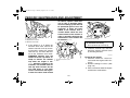
OWNER’S MANUAL
YZFR1B(C)
LIT-11626-25-45
1KB-28199-11
DIC183
U1KB11E0.book Page 1 Monday, August 8, 2011 11:14 AM
EAU10042
Read this manual carefully before operating this vehicle. This manual should stay with this vehicle if it is sold.
U1KB11E0.book Page 1 Monday, August 8, 2011 11:14 AM
INTRODUCTION
EAU10083
Congratulations on your purchase of the Yamaha YZFR1B(C). This model is the result of Yamaha’s vast experience in the
production of fine sporting, touring, and pacesetting racing machines. It represents the high degree of craftsmanship and
reliability that have made Yamaha a leader in these fields.
This manual will give you an understanding of the operation, inspection, and basic maintenance of this motorcycle. If you
have any questions concerning the operation or maintenance of your motorcycle, please consult a Yamaha dealer.
The design and manufacture of this Yamaha motorcycle fully comply with the emissions standards for clean air applicable at
the date of manufacture. Yamaha has met these standards without reducing the performance or economy of operation of the
motorcycle. To maintain these high standards, it is important that you and your Yamaha dealer pay close attention to the
recommended maintenance schedules and operating instructions contained within this manual.
Yamaha continually seeks advancements in product design and quality. Therefore, while this manual contains the most current product information available at the time of printing, there may be minor discrepancies between your motorcycle and this
manual. If there is any question concerning this manual, please consult a Yamaha dealer.
EWA10011
WARNING
Please read this manual and the “YOU AND YOUR MOTORCYCLE: RIDING TIPS” booklet carefully before operating
this motorcycle. Do not attempt to operate this motorcycle until you have attained adequate knowledge of its controls and operating features. Regular inspections and careful maintenance, along with good operating techniques,
will help ensure that you safely enjoy the capabilities and reliability of this motorcycle.
U1KB11E0.book Page 1 Monday, August 8, 2011 11:14 AM
IMPORTANT MANUAL INFORMATION
EAU10133
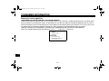
Particularly important information is distinguished in this manual by the following notations:
This is the safety alert symbol. It is used to alert you to potential personal injury
hazards. Obey all safety messages that follow this symbol to avoid possible injury
or death.
WARNING
NOTICE
TIP
A WARNING indicates a hazardous situation which, if not avoided, could result in
death or serious injury.
A NOTICE indicates special precautions that must be taken to avoid damage to the
vehicle or other property.
A TIP provides key information to make procedures easier or clearer.
*Product and specifications are subject to change without notice.
U1KB11E0.book Page 2 Monday, August 8, 2011 11:14 AM
IMPORTANT MANUAL INFORMATION
EAU10193
YZFR1B(C)
OWNER’S MANUAL
©2011 by Yamaha Motor Corporation, U.S.A.
1st edition, July 2011
All rights reserved.
Any reprinting or unauthorized use
without the written permission of
Yamaha Motor Corporation, U.S.A.
is expressly prohibited.
Printed in Japan.
P/N LIT-11626-25-45
U1KB11E0.book Page 1 Monday, August 8, 2011 11:14 AM
TABLE OF CONTENTS
LOCATION OF IMPORTANT
LABELS .............................................1-1
SAFETY INFORMATION ..................2-1
DESCRIPTION ..................................3-1
Left view ..........................................3-1
Right view ........................................3-2
Controls and instruments.................3-3
INSTRUMENT AND CONTROL
FUNCTIONS .......................................4-1
D-mode (drive mode) ......................4-1
Main switch/steering lock ................4-1
Indicator lights and
warning lights ..............................4-3
Multi-function meter unit .................4-7
Handlebar switches ......................4-15
Clutch lever ...................................4-17
Shift pedal .....................................4-17
Brake lever ...................................4-17
Brake pedal ..................................4-18
Traction control system ................4-18
Fuel tank cap ................................4-21
Fuel ...............................................4-21
Fuel tank breather hose and
overflow hose ............................4-23
Catalytic converter ........................4-23
Seats ............................................4-24
Helmet holder ...............................4-25
Storage compartment ...................4-26
Rider footrest position .................. 4-26
Rear view mirrors ......................... 4-27
Adjusting the front fork ................. 4-27
Adjusting the shock absorber
assembly ................................... 4-29
Luggage strap holders ................. 4-31
Sidestand ..................................... 4-32
Ignition circuit cut-off system ........ 4-32
FOR YOUR SAFETY –
PRE-OPERATION CHECKS ............. 5-1
OPERATION AND IMPORTANT
RIDING POINTS................................. 6-1
Starting the engine ......................... 6-1
Shifting ........................................... 6-2
Engine break-in .............................. 6-3
Parking ........................................... 6-4
PERIODIC MAINTENANCE AND
ADJUSTMENT ................................... 7-1
Owner’s tool kit ............................... 7-2
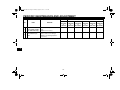
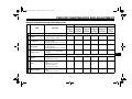
Periodic maintenance chart for
the emission control system ....... 7-3
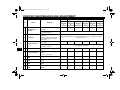
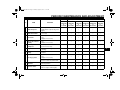
General maintenance and
lubrication chart .......................... 7-5
Removing and installing
cowlings ...................................... 7-9
Checking the spark plugs ............. 7-11
Canister (for California only) ........ 7-12
Engine oil and oil filter cartridge ... 7-13
Coolant ........................................ 7-15
Air filter element ........................... 7-18
Checking the engine idling
speed ........................................ 7-19
Checking the throttle grip free
play ........................................... 7-19
Valve clearance ........................... 7-19
Tires ............................................. 7-20
Cast wheels ................................. 7-22
Adjusting the clutch lever free
play ........................................... 7-22
Checking the brake lever free
play ........................................... 7-23
Brake light switches ..................... 7-24
Checking the front and
rear brake pads ........................ 7-24
Checking the brake fluid level ...... 7-25
Changing the brake fluid .............. 7-26
Drive chain slack .......................... 7-26
Cleaning and lubricating
the drive chain .......................... 7-28
Checking and lubricating
the cables ................................. 7-28
Checking and lubricating
the throttle grip and cable ......... 7-29
Checking and lubricating
the brake and shift pedals ........ 7-29
Checking and lubricating
the brake and clutch levers ...... 7-30
Checking and lubricating
the sidestand ............................ 7-30
U1KB11E0.book Page 2 Monday, August 8, 2011 11:14 AM
TABLE OF CONTENTS
Lubricating the swingarm
pivots .........................................7-31
Checking the front fork .................7-31
Checking the steering ...................7-32
Checking the wheel bearings .......7-32
Battery ..........................................7-32
Replacing the fuses ......................7-34
Replacing a headlight bulb ...........7-35
Tail/brake light ..............................7-37
Replacing a turn signal light
bulb ...........................................7-37
Replacing the license plate light
bulb ...........................................7-38
Auxiliary light ................................7-38
Supporting the motorcycle ............7-39
Troubleshooting ............................7-39
Troubleshooting charts .................7-41
MOTORCYCLE CARE AND
STORAGE ..........................................8-1
Matte color caution .........................8-1
Care ................................................8-1
Storage ...........................................8-4
SPECIFICATIONS .............................9-1
CONSUMER INFORMATION...........10-1
Identification numbers ..................10-1
Reporting safety defects ...............10-3
Motorcycle noise regulation ..........10-4
Maintenance record ......................10-5
YAMAHA MOTOR
CORPORATION, U.S.A.
STREET AND ENDURO
MOTORCYCLE LIMITED
WARRANTY ............................. 10-7
YAMAHA EXTENDED SERVICE
(Y.E.S.) ..................................... 10-9
U1KB11E0.book Page 1 Monday, August 8, 2011 11:14 AM
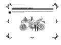
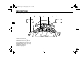
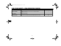
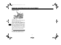
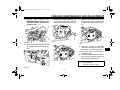
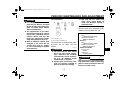
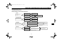
LOCATION OF IMPORTANT LABELS
EAU10384
1
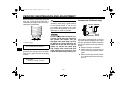
Read and understand all of the labels on your vehicle. They contain important information for safe and proper operation of
your vehicle. Never remove any labels from your vehicle. If a label becomes difficult to read or comes off, a replacement label
is available from your Yamaha dealer.
1
2,3
4
5,6
8
1-1
7
U1KB11E0.book Page 2 Monday, August 8, 2011 11:14 AM
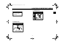
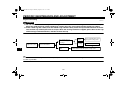
LOCATION OF IMPORTANT LABELS
1
3 California only
NOTICE
EMISSION HOSE ROUTING
FUEL TANK ATMOSPHERE
#3
#4
Cleaning with alkaline or
acid cleaner, gasoline or
solvent will damage
windshield.
Use neutral detergent.
#1
#2
4B5-2815K-00
CHARCOAL
THROTTLE BODY CANISTER
14B-21686-00
2 California only
VACUUM HOSE ROUTING
PRESS. SENSOR
#1
#2
#3
#4
INTAKE MANIFOLD
14B-21684-00
1-2
1
U1KB11E0.book Page 3 Monday, August 8, 2011 11:14 AM
LOCATION OF IMPORTANT LABELS
4
7
WARNING
1
BEFORE YOU OPERATE THIS VEHICLE, READ
THE OWNER’S MANUAL AND ALL LABELS.
ALWAYS WEAR AN APPROVED MOTORCYCLE
HELMET, eye protection, and protective clothing.
Cold tire normal pressure should be set
as follows.
Up to 90 kg (198 lbs) load
: 250 kPa, {2.50 kgf/cm 2 }, 36 psi
: 290 kPa, {2.90 kgf/cm 2 }, 42 psi
90 kg (198 lbs)~maximum load
: 250 kPa, {2.50 kgf/cm 2 }, 36 psi
: 290 kPa, {2.90 kgf/cm 2 }, 42 psi
PREMIUM UNLEADED GASOLINE ONLY
91 Min. Pump Octane (R+M)/2
4C8-2118K-00
14B-21668-00
5
8
LOAD LIMIT
1 kg {2 lbs}
4BR-24877-A0
6
3JJ-28446-A1
1-3
U1KB11E0.book Page 1 Monday, August 8, 2011 11:14 AM
SAFETY INFORMATION
EAU10289
Be a Responsible Owner
As the vehicle’s owner, you are responsible for the safe and proper operation
of your motorcycle.
Motorcycles are single-track vehicles.
Their safe use and operation are dependent upon the use of proper riding
techniques as well as the expertise of
the operator. Every operator should
know the following requirements before
riding this motorcycle.
He or she should:
● Obtain thorough instructions from
a competent source on all aspects
of motorcycle operation.
● Observe the warnings and maintenance requirements in this Owner’s Manual.
● Obtain qualified training in safe
and proper riding techniques.
● Obtain professional technical service as indicated in this Owner’s
Manual and/or when made necessary by mechanical conditions.
Safe Riding
Perform the pre-operation checks each
time you use the vehicle to make sure it
is in safe operating condition. Failure to
inspect or maintain the vehicle properly
increases the possibility of an accident
or equipment damage. See page 5-1
for a list of pre-operation checks.
● This motorcycle is designed to carry the operator and a passenger.
● The failure of motorists to detect
and recognize motorcycles in traffic is the predominating cause of
automobile/motorcycle accidents.
Many accidents have been caused
by an automobile driver who did
not see the motorcycle. Making
yourself conspicuous appears to
be very effective in reducing the
chance of this type of accident.
Therefore:
• Wear a brightly colored jacket.
• Use extra caution when you are
approaching
and
passing
through intersections, since intersections are the most likely
places for motorcycle accidents
to occur.
2-1
●
●
• Ride where other motorists can
see you. Avoid riding in another
motorist’s blind spot.
Many accidents involve inexperienced operators. In fact, many operators who have been involved in
accidents do not even have a current motorcycle license.
• Make sure that you are qualified
and that you only lend your motorcycle to other qualified operators.
• Know your skills and limits.
Staying within your limits may
help you to avoid an accident.
• We recommend that you practice riding your motorcycle
where there is no traffic until you
have become thoroughly familiar with the motorcycle and all of
its controls.
Many accidents have been caused
by error of the motorcycle operator. A typical error made by the operator is veering wide on a turn
2
U1KB11E0.book Page 2 Monday, August 8, 2011 11:14 AM
SAFETY INFORMATION
2
●
●
due to excessive speed or undercornering (insufficient lean angle
for the speed).
• Always obey the speed limit and
never travel faster than warranted by road and traffic conditions.
• Always signal before turning or
changing lanes. Make sure that
other motorists can see you.
The posture of the operator and
passenger is important for proper
control.
• The operator should keep both
hands on the handlebar and
both feet on the operator footrests during operation to maintain control of the motorcycle.
• The passenger should always
hold onto the operator, the seat
strap or grab bar, if equipped,
with both hands and keep both
feet on the passenger footrests.
Never carry a passenger unless
he or she can firmly place both
feet on the passenger footrests.
Never ride under the influence of
alcohol or other drugs.
●
This motorcycle is designed for onroad use only. It is not suitable for
off-road use.
Protective Apparel
The majority of fatalities from motorcycle accidents are the result of head injuries. The use of a safety helmet is the
single most critical factor in the prevention or reduction of head injuries.
● Always wear an approved helmet.
● Wear a face shield or goggles.
Wind in your unprotected eyes
could contribute to an impairment
of vision that could delay seeing a
hazard.
● The use of a jacket, heavy boots,
trousers, gloves, etc., is effective in
preventing or reducing abrasions
or lacerations.
● Never wear loose-fitting clothes,
otherwise they could catch on the
control levers, footrests, or wheels
and cause injury or an accident.
● Always wear protective clothing
that covers your legs, ankles, and
feet. The engine or exhaust system become very hot during or after operation and can cause burns.
2-2
●
A passenger should also observe
the above precautions.
Avoid Carbon Monoxide Poisoning
All engine exhaust contains carbon
monoxide, a deadly gas. Breathing carbon monoxide can cause headaches,
dizziness, drowsiness, nausea, confusion, and eventually death.
Carbon Monoxide is a colorless, odorless, tasteless gas which may be
present even if you do not see or smell
any engine exhaust. Deadly levels of
carbon monoxide can collect rapidly
and you can quickly be overcome and
unable to save yourself. Also, deadly
levels of carbon monoxide can linger
for hours or days in enclosed or poorly
ventilated areas. If you experience any
symptoms of carbon monoxide poisoning, leave the area immediately, get
fresh air, and SEEK MEDICAL TREATMENT.
● Do not run engine indoors. Even if
you try to ventilate engine exhaust
with fans or open windows and
doors, carbon monoxide can rapidly reach dangerous levels.
U1KB11E0.book Page 3 Monday, August 8, 2011 11:14 AM
SAFETY INFORMATION
●
●
Do not run engine in poorly ventilated or partially enclosed areas
such as barns, garages, or carports.
Do not run engine outdoors where
engine exhaust can be drawn into
a building through openings such
as windows and doors.
Loading
Adding accessories or cargo to your
motorcycle can adversely affect stability and handling if the weight distribution
of the motorcycle is changed. To avoid
the possibility of an accident, use extreme caution when adding cargo or
accessories to your motorcycle. Use
extra care when riding a motorcycle
that has added cargo or accessories.
Here, along with the information about
accessories below, are some general
guidelines to follow if loading cargo to
your motorcycle:
The total weight of the operator, passenger, accessories and cargo must
not exceed the maximum load limit.
Operation of an overloaded vehicle
could cause an accident.
Maximum load:
189 kg (417 lb)
When loading within this weight limit,
keep the following in mind:
● Cargo and accessory weight
should be kept as low and close to
the motorcycle as possible. Securely pack your heaviest items as
close to the center of the vehicle as
possible and make sure to distribute the weight as evenly as possible on both sides of the motorcycle
to minimize imbalance or instability.
● Shifting weights can create a sudden imbalance. Make sure that accessories and cargo are securely
attached to the motorcycle before
riding. Check accessory mounts
and cargo restraints frequently.
• Properly adjust the suspension
for your load (suspension-adjustable models only), and
check the condition and pressure of your tires.
• Never attach any large or heavy
items to the handlebar, front
fork, or front fender. These
2-3
●
items, including such cargo as
sleeping bags, duffel bags, or
tents, can create unstable handling or a slow steering response.
This vehicle is not designed to
pull a trailer or to be attached to
a sidecar.
Genuine Yamaha Accessories
Choosing accessories for your vehicle
is an important decision. Genuine
Yamaha accessories, which are available only from a Yamaha dealer, have
been designed, tested, and approved
by Yamaha for use on your vehicle.
Many companies with no connection to
Yamaha manufacture parts and accessories or offer other modifications for
Yamaha vehicles. Yamaha is not in a
position to test the products that these
aftermarket
companies
produce.
Therefore, Yamaha can neither endorse nor recommend the use of accessories not sold by Yamaha or
modifications not specifically recommended by Yamaha, even if sold and
installed by a Yamaha dealer.
2
U1KB11E0.book Page 4 Monday, August 8, 2011 11:14 AM
SAFETY INFORMATION
2
Aftermarket Parts, Accessories, and
Modifications
While you may find aftermarket products similar in design and quality to
genuine Yamaha accessories, recognize that some aftermarket accessories
or modifications are not suitable because of potential safety hazards to you
or others. Installing aftermarket products or having other modifications performed to your vehicle that change any
of the vehicle’s design or operation
characteristics can put you and others
at greater risk of serious injury or death.
You are responsible for injuries related
to changes in the vehicle.
Keep the following guidelines in mind,
as well as those provided under “Loading” when mounting accessories.
● Never install accessories or carry
cargo that would impair the performance of your motorcycle. Carefully inspect the accessory before
using it to make sure that it does
not in any way reduce ground
clearance or cornering clearance,
limit suspension travel, steering
travel or control operation, or obscure lights or reflectors.
• Accessories fitted to the handlebar or the front fork area can
create instability due to improper
weight distribution or aerodynamic changes. If accessories
are added to the handlebar or
front fork area, they must be as
lightweight as possible and
should be kept to a minimum.
• Bulky or large accessories may
seriously affect the stability of
the motorcycle due to aerodynamic effects. Wind may attempt to lift the motorcycle, or
the motorcycle may become unstable in cross winds. These accessories may also cause
instability when passing or being
passed by large vehicles.
• Certain accessories can displace the operator from his or
her normal riding position. This
improper position limits the freedom of movement of the opera-
2-4
●
tor and may limit control ability,
therefore, such accessories are
not recommended.
Use caution when adding electrical accessories. If electrical accessories exceed the capacity of the
motorcycle’s electrical system, an
electric failure could result, which
could cause a dangerous loss of
lights or engine power.
Aftermarket Tires and Rims
The tires and rims that came with your
motorcycle were designed to match the
performance capabilities and to provide
the best combination of handling, braking, and comfort. Other tires, rims, sizes, and combinations may not be
appropriate. Refer to page 7-20 for tire
specifications and more information on
replacing your tires.
Transporting the Motorcycle
Be sure to observe following instructions before transporting the motorcycle in another vehicle.
● Remove all loose items from the
motorcycle.
U1KB11E0.book Page 5 Monday, August 8, 2011 11:14 AM
SAFETY INFORMATION
●
●
●
●
●
Check that the fuel cock (if
equipped) is in the “OFF” position
and that there are no fuel leaks.
Point the front wheel straight
ahead on the trailer or in the truck
bed, and choke it in a rail to prevent movement.
Shift the transmission in gear (for
models with a manual transmission).
Secure the motorcycle with tiedowns or suitable straps that are
attached to solid parts of the motorcycle, such as the frame or upper front fork triple clamp (and not,
for example, to rubber-mounted
handlebars or turn signals, or parts
that could break). Choose the location for the straps carefully so
the straps will not rub against
painted surfaces during transport.
The suspension should be compressed somewhat by the tiedowns, if possible, so that the motorcycle will not bounce excessively during transport.
2
2-5
U1KB11E0.book Page 1 Monday, August 8, 2011 11:14 AM
DESCRIPTION
EAU10410
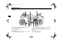
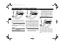
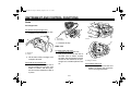
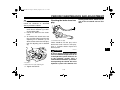
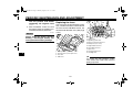
Left view
1,2
3
13
12 11
4,5,6
3
1.
2.
3.
4.
5.
6.
7.
10
9
7,8
8. Shock absorber assembly compression damping force adjusting bolt
(for slow compression damping) (page 4-29)
9. Shock absorber assembly spring preload adjusting screw (page 4-29)
10.Shock absorber assembly rebound damping force adjusting screw
(page 4-29)
11.Engine oil drain bolt (page 7-13)
12.Coolant drain bolt (page 7-16)
13.Engine oil filter cartridge (page 7-13)
Front fork spring preload adjusting bolt (page 4-27)
Front fork compression damping force adjusting screw (page 4-27)
Coolant reservoir (page 7-15)
Fuel injection system fuse (page 7-34)
Main fuse (page 7-34)
Fuse box (page 7-34)
Shock absorber assembly compression damping force adjusting bolt
(for fast compression damping) (page 4-29)
3-1
U1KB11E0.book Page 2 Monday, August 8, 2011 11:14 AM
DESCRIPTION
EAU10420
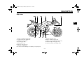
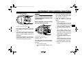
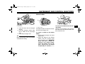
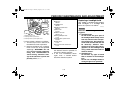
Right view
1,2,3 4
5,6
7
8
9
3
13
1.
2.
3.
4.
5.
6.
7.
8.
12
11
10
9. Radiator cap (page 7-15)
10.Engine oil filler cap (page 7-13)
11.Engine oil level check window (page 7-13)
12.Rear brake light switch (page 7-24)
13.Rear brake fluid reservoir (page 7-25)
Storage compartment (page 4-26)
Luggage strap holder (page 4-31)
Helmet holder (page 4-25)
Seat lock (page 4-24)
Battery (page 7-32)
Owner’s tool kit (page 7-2)
Fuel tank cap (page 4-21)
Front fork rebound damping force adjusting screw (page 4-27)
3-2
U1KB11E0.book Page 3 Monday, August 8, 2011 11:14 AM
DESCRIPTION
EAU10430
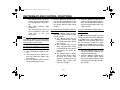
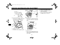
Controls and instruments
1
2
3
4
3
1.
2.
3.
4.
5.
6.
7.
8.
Clutch lever (page 4-17)
Left handlebar switches (page 4-15)
Main switch/steering lock (page 4-1)
Multi-function meter unit (page 4-7)
Front brake fluid reservoir (page 7-25)
Right handlebar switches (page 4-15)
Throttle grip (page 7-19)
Brake lever (page 4-17)
3-3
5
6
7
8
U1KB11E0.book Page 1 Monday, August 8, 2011 11:14 AM
INSTRUMENT AND CONTROL FUNCTIONS
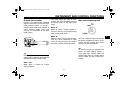
EAU47632
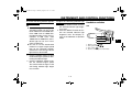
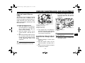
D-mode (drive mode)
D-mode is an electronically controlled
engine performance system with three
mode selections (“STD”, “A”, and “B”).
Push the drive mode switch “MODE” to
switch between modes. (See page
4-16 for an explanation of the drive
mode switch.)
1
This mode allows the rider to enjoy
smooth and sporty drivability from the
low-speed range to the high-speed
range.
EAU10460
Main switch/steering lock
Mode “A”
Mode “A” offers a sportier engine response in the low- to mid-speed range
compared to mode “STD”.
Mode “B”
Mode “B” offers response that is somewhat less sharp compared to mode
“STD” for riding situations that require
especially sensitive throttle operation.
4
The main switch/steering lock controls
the ignition and lighting systems, and is
used to lock the steering. The various
positions are described below.
EAU10600
ON
All electrical circuits are supplied with
power, the meter lighting, taillight, license plate light, auxiliary lights and
position lights come on, and the engine
can be started. The key cannot be removed.
1. Drive mode switch “MODE”
TIP
Before using D-mode, make sure you
understand its operation along with the
operation of the drive mode switch.
Mode “STD”
Mode “STD” is suitable for various
riding conditions.
4-1
U1KB11E0.book Page 2 Monday, August 8, 2011 11:14 AM
INSTRUMENT AND CONTROL FUNCTIONS
TIP
The headlights come on automatically
when the engine is started and stay on
until the key is turned to “OFF”, even if
the engine stalls.
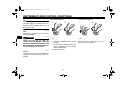
To lock the steering
1
To unlock the steering
2
1
2
EAU10661
OFF
All electrical systems are off. The key
can be removed.
4
EWA10061
WARNING
Never turn the key to “OFF” or
“LOCK” while the vehicle is moving.
Otherwise the electrical systems will
be switched off, which may result in
loss of control or an accident.
EAU10683
1. Push.
2. Turn.
1. Push.
2. Turn.
1. Turn the handlebars all the way to
the left.
2. Push the key in from the “OFF” position, and then turn it to “LOCK”
while still pushing it.
3. Remove the key.
LOCK
The steering is locked, and all electrical
systems are off. The key can be removed.
4-2
Push the key in, and then turn it to
“OFF” while still pushing it.
U1KB11E0.book Page 3 Monday, August 8, 2011 11:14 AM
INSTRUMENT AND CONTROL FUNCTIONS
EAU49391
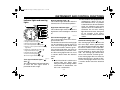
Indicator lights and warning
lights
1
2
3
4
5
6
7
8
9
10
1.
2.
3.
4.
5.
Shift timing indicator light
Engine trouble warning light “
”
Oil level warning light “
”
Coolant temperature warning light “
”
Traction control system indicator/warning
light “TCS”
6. Right turn signal indicator light “
”
7. High beam indicator light “
”
8. Neutral indicator light “
”
9. Fuel level warning light “ ”
10.Left turn signal indicator light “
”
EAU11030
Turn signal indicator lights “ ”
and “ ”
The corresponding indicator light flashes when the turn signal switch is
pushed to the left or right.
EAU11060
Neutral indicator light “ ”
This indicator light comes on when the
transmission is in the neutral position.
EAU11080
High beam indicator light “ ”
This indicator light comes on when the
high beam of the headlight is switched
on.
EAU11254
Oil level warning light “
”
This warning light comes on if the engine oil level is low.
The electrical circuit of the warning light
can be checked by turning the key to
“ON”. The warning light should come
on for a few seconds, and then go off.
If the warning light does not come on
initially when the key is turned to “ON”,
or if the warning light remains on, have
a Yamaha dealer check the electrical
circuit.
TIP
●
Even if the oil level is sufficient, the
warning light may flicker when
riding on a slope or during sudden
acceleration or deceleration, but
this is not a malfunction.
4-3
●
This model is also equipped with a
self-diagnosis device for the oil
level detection circuit. If a problem
is detected in the oil level detection
circuit, the following cycle will be
repeated until the malfunction is
corrected: The oil level warning
light will flash ten times, then go off
for 2.5 seconds. If this occurs,
have a Yamaha dealer check the
vehicle.
EAU11365
Fuel level warning light “ ”
This warning light comes on when the
fuel level drops below approximately
3.1 L (0.82 US gal, 0.68 Imp.gal). When
this occurs, refuel as soon as possible.
The electrical circuit of the warning light
can be checked by turning the key to
“ON”. The warning light should come
on for a few seconds, and then go off.
If the warning light does not come on
initially when the key is turned to “ON”,
or if the warning light remains on, have
a Yamaha dealer check the electrical
circuit.
4
U1KB11E0.book Page 4 Monday, August 8, 2011 11:14 AM
INSTRUMENT AND CONTROL FUNCTIONS
ECA10021
4
TIP
This model is also equipped with a selfdiagnosis device for the fuel level detection circuit. If a problem is detected
in the fuel level detection circuit, the following cycle will be repeated until the
malfunction is corrected: The fuel level
warning light will flash eight times, and
then go off for 3.0 seconds. If this occurs, have a Yamaha dealer check the
vehicle.
EAU47752
NOTICE
Do not continue to operate the engine if it is overheating.
TIP
●
●
For radiator-fan-equipped vehicles, the radiator fan(s) automatically switch on or off according to
the coolant temperature in the radiator.
If the engine overheats, see page
7-42 for further instructions.
Coolant temperature warning
light “ ”
This warning light comes on if the engine overheats. If this occurs, stop the
engine immediately and allow the engine to cool.
The electrical circuit of the warning light
can be checked by turning the key to
“ON”. The warning light should come
on for a few seconds, and then go off.
If the warning light does not come on
initially when the key is turned to “ON”,
or if the warning light remains on, have
a Yamaha dealer check the electrical
circuit.
4-4
U1KB11E0.book Page 5 Monday, August 8, 2011 11:14 AM
INSTRUMENT AND CONTROL FUNCTIONS
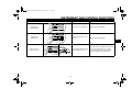
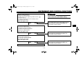
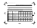
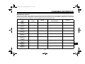
Display
Conditions
What to do
Under 39 °C
(Under 103 °F)
Message “Lo” is displayed.
OK. Go ahead with riding.
40–116 °C
(104–242 °F)
Coolant temperature is displayed.
OK. Go ahead with riding.
4
Above 117 °C
(Above 243 °F)
Coolant temperature flashes.
Warning light comes on.
4-5
Stop the vehicle and allow it to idle until
the coolant temperature goes down.
If the temperature does not go down,
stop the engine. (See page 7-42.)
U1KB11E0.book Page 6 Monday, August 8, 2011 11:14 AM
INSTRUMENT AND CONTROL FUNCTIONS
EAU11534
4
Engine trouble warning light “ ”
This warning light comes on or flashes
if a problem is detected in the electrical
circuit monitoring the engine. If this occurs, have a Yamaha dealer check the
self-diagnosis system. (See page 4-13
for an explanation of the self-diagnosis
device.)
The electrical circuit of the warning light
can be checked by turning the key to
“ON”. The warning light should come
on for a few seconds, and then go off.
If the warning light does not come on
initially when the key is turned to “ON”,
or if the warning light remains on, have
a Yamaha dealer check the electrical
circuit.
If the light does not come on initially
when the key is turned to “ON”, or if the
light remains on, have a Yamaha dealer check the electrical circuit.
When the traction control system is set
to a “TCS” mode other than “OFF”, and
the traction control system is operating,
the indicator light flashes.
If the traction control system disables
while riding, “TCS OFF” is displayed,
and the indicator/warning light and engine trouble warning light come on.
(See page 4-18 for an explanation of
the traction control system.)
1
2
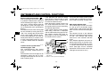
EAU51850
Traction control system indicator/warning light “TCS”
This indicator/warning light flashes
when the traction control system engages.
The electrical circuit of the light can be
checked by turning the key to “ON”.
The light should come on for a few seconds, and then go off.
3
1. Engine trouble warning light “
”
2. Traction control system indicator/warning
light “TCS”
3. Traction control system mode display
4-6
Try to reset the traction control system
and the lights by following the procedures under “Resetting” on page 4-20.
EAU11574
Shift timing indicator light
This indicator light can be set to come
on and go off at the desired engine
speeds and is used to inform the rider
when it is time to shift to the next higher
gear.
The electrical circuit of the indicator
light can be checked by turning the key
to “ON”. The indicator light should
come on for a few seconds, and then
go off.
If the indicator light does not come on
initially when the key is turned to “ON”,
or if the indicator light remains on, have
a Yamaha dealer check the electrical
circuit. (See page 4-13 for a detailed
explanation of the function of this indicator light and on how to set it.)
U1KB11E0.book Page 7 Thursday, March 29, 2012 2:54 PM
INSTRUMENT AND CONTROL FUNCTIONS
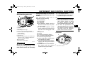
EAU51832
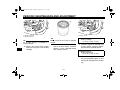
Multi-function meter unit
2
4
3
1 11
5
6
7
8
9
10
1.
2.
3.
4.
5.
6.
“RESET” button
“SELECT” button
Tachometer
Shift timing indicator light
Traction control system mode display
Coolant temperature display/air intake temperature display
7. Drive mode display
8. Speedometer
9. Odometer/tripmeter/fuel reserve tripmeter/instantaneous fuel consumption display/average fuel consumption display
10.Clock/stopwatch
11.Transmission gear display
EWA12422
WARNING
Be sure to stop the vehicle before
making any setting changes to the
multi-function meter unit. Changing
settings while riding can distract the
operator and increase the risk of an
accident.
●
The multi-function meter unit is
equipped with the following:
● a speedometer
● a tachometer
● an odometer
● two tripmeters (which show the
distance traveled since they were
last set to zero)
● a fuel reserve tripmeter (which
shows the distance traveled since
the fuel level warning light came
on)
● a stopwatch
● a clock
● a coolant temperature display
● an air intake temperature display
● a transmission gear display
● a drive mode display (which shows
the selected drive mode)
● a fuel consumption display (instantaneous and average consumption
functions)
● a traction control system mode display (which shows the selected
traction control system mode)
TIP
4-7
●
●
●
a self-diagnosis device
a display brightness and shift timing indicator light control mode
Be sure to turn the key to “ON” before using the “SELECT” and “RESET” buttons, except for setting
the display brightness and shift
timing indicator light control mode.
To switch the speedometer and
odometer/tripmeter/fuel consumption displays between kilometers
and miles, press the “SELECT”
button for at least one second.
Tachometer
1
2
1. Tachometer
2. Tachometer red zone
4
U1KB11E0.book Page 8 Monday, August 8, 2011 11:14 AM
INSTRUMENT AND CONTROL FUNCTIONS
The electric tachometer allows the rider
to monitor the engine speed and keep it
within the ideal power range.
When the key is turned to “ON”, the tachometer needle sweeps once across
the r/min range and then returns to zero
r/min in order to test the electrical circuit.
ECA10031
NOTICE
4
Do not operate the engine in the tachometer red zone.
Red zone: 13750 r/min and above
Clock and stopwatch modes
1
1. Clock/stopwatch
To set the clock
1. Push the “SELECT” button and
“RESET” button together for at
least two seconds.
2. When the hour digits start flashing,
push the “RESET” button to set the
hours.
3. Push the “SELECT” button, and
the minute digits start flashing.
4. Push the “RESET” button to set
the minutes.
5. Push the “SELECT” button and
then release it to start the clock.
To display the stopwatch
To change the display to the stopwatch
mode, push the “SELECT” button and
“RESET” button together. To change
the display back to the clock mode,
push the “SELECT” button and “RESET” button together; however, this is
not possible when the stopwatch is
counting.
Standard measurement
1. Push the “RESET” button to start
the stopwatch.
2. Push the “SELECT” button to stop
the stopwatch.
4-8
3. Push the “SELECT” button again
to reset the stopwatch.
Split time measurement
1. Push the “RESET” button to start
the stopwatch.
2. Push the start switch “ ” or “RESET” button to measure split
times. Split times are displayed on
the odometer display for five seconds.
3. Push the start switch “ ” or “RESET” button to display the final
split time or push the “SELECT”
button to stop the stopwatch and
display the final split time.
U1KB11E0.book Page 9 Monday, August 8, 2011 11:14 AM
INSTRUMENT AND CONTROL FUNCTIONS
Split time history
TIP
●
1
●
2
1. Coolant temperature display/air intake temperature display
2. Stopwatch
The split time history displays up to 20
stored split times. The split time history
can be displayed either in reverse chronological order or by speed.
1. Push the “SELECT” button for at
least one second to select the reverse chronological order mode;
“L-20” displays on the stopwatch.
Push the “SELECT” button again
to select the speed mode; “F-20”
displays on the stopwatch.
Reverse
chronological
order
mode: The split times are shown
from the latest to earliest (i.e., L1,
L2, L3, L4).
Speed order mode: The split times
are shown from the fastest to slowest (i.e., F1, F2, F3, F4).
2. Push the “RESET” button. Depending on the selected split time,
“L1” or “F1” displays on the coolant
temperature display/air intake
temperature display, and its corresponding stored split time displays
on the stopwatch.
3. Push the “SELECT” button to
switch the displayed split time in
ascending order (i.e., 1, 2, 3, 4),
and the “RESET” button to switch
the displayed split time in descending order (i.e., 20, 19, 18,
17).
●
cancel the currently selected
mode, and then repeat step 1 to
select the desired mode.
To reset all the recorded times for
the selected split time history,
push the “RESET” button for at
least one second.
4. Push the “SELECT” button for at
least one second to cancel the split
time history and return to the time
measurement.
Odometer, tripmeter, instantaneous
fuel consumption and average fuel
consumption modes
1
TIP
●
To switch between the reverse
chronological order mode and the
speed mode, push the “SELECT”
button for at least one second to
4-9
1. Odometer/tripmeter/fuel reserve tripmeter/instantaneous fuel consumption display/average fuel consumption display
4
U1KB11E0.book Page 10 Thursday, March 29, 2012 2:55 PM
INSTRUMENT AND CONTROL FUNCTIONS
Push the “SELECT” button to switch
the display between the odometer
mode “ODO”, the tripmeter modes
“TRIP 1” and “TRIP 2”, the instantaneous fuel consumption mode “km/L”,
“L/100 km” or “MPG”, and the average
fuel consumption mode “AVE_ _._
km/L”, “AVE_ _._ L/100 km” or “AVE_
_._ MPG” in the following order:
4
ODO → TRIP 1 → TRIP 2 → km/L,
L/100 km or MPG → AVE_ _._ km/L,
AVE_ _._ L/100 km or AVE_ _._ MPG
→ ODO
If the fuel level warning light comes on
(see page 4-3), the display automatically changes to the fuel reserve tripmeter
mode “TRIP F” and starts counting the
distance traveled from that point. In that
case, push the “SELECT” button to
switch the display between the various
tripmeter, odometer, instantaneous fuel
consumption and average fuel consumption modes in the following order:
TRIP F → km/L, L/100 km or MPG →
AVE_ _._ km/L, AVE_ _._ L/100 km or
AVE_ _._ MPG → ODO → TRIP 1 →
TRIP 2 → TRIP F
To reset a tripmeter, select it by pushing the “SELECT” button, and then
push the “RESET” button for at least
one second.
If you do not reset the fuel reserve tripmeter manually, it resets itself automatically and the display returns to the prior
mode after refueling and traveling 5 km
(3 mi).
Instantaneous fuel consumption mode
The instantaneous fuel consumption
display can be set to either “km/L”,
“L/100 km” or “MPG”.
● “km/L”: The distance that can be
traveled on 1.0 L of fuel under the
current riding conditions is shown.
● “L/100 km”: The amount of fuel
necessary to travel 100 km under
the current riding conditions is
shown.
● “MPG”: The distance that can be
traveled on 1.0 US gal of fuel under the current riding conditions is
shown.
To switch between the instantaneous
fuel consumption displays, push the
“SELECT” button for one second when
one of the displays is shown.
TIP
If traveling at speeds under 10 km/h
(6.0 mi/h), “_ _._” is displayed.
1
1. Instantaneous fuel consumption display
4-10
U1KB11E0.book Page 11 Thursday, March 29, 2012 2:55 PM
INSTRUMENT AND CONTROL FUNCTIONS
Average fuel consumption mode
1
1. Average fuel consumption display
The average fuel consumption display
can be set to either “AVE_ _._ km/L”,
“AVE_ _._ L/100 km” or “AVE_ _._
MPG”.
This display shows the average fuel
consumption since it was last reset.
● “AVE_ _._ km/L”: The average distance that can be traveled on 1.0 L
of fuel is shown.
● “AVE_ _._ L/100 km”: The average
amount of fuel necessary to travel
100 km is shown.
● “AVE_ _._ MPG”: The average
distance that can be traveled on
1.0 US gal of fuel is shown.
To switch between the average fuel
consumption displays, push the “SELECT” button for one second when one
of the displays is shown.
To reset the average fuel consumption
display, select it by pushing the “SELECT” button, and then push the “RESET” button for at least one second.
This display shows the selected gear.
The neutral position is indicated by “ ”
and by the neutral indicator light.
Drive mode display
1
TIP
After resetting an average fuel consumption display, “_ _._” is shown for
that display until the vehicle has traveled 1 km (0.6 mi).
1. Drive mode display
Transmission gear display
1
2
1. Neutral indicator light “
”
2. Transmission gear display
4-11
4
This display indicates which drive
mode has been selected: “STD”, “A” or
“B”. For more details on the modes and
on how to select them, refer to pages
4-1 and 4-16.
U1KB11E0.book Page 12 Monday, August 8, 2011 11:14 AM
INSTRUMENT AND CONTROL FUNCTIONS
Coolant temperature display
●
Air intake temperature display
1
1
●
4
1. Coolant temperature display
1. Air intake temperature display
The coolant temperature display indicates the temperature of the coolant.
The air intake temperature display indicates the temperature of the air drawn
into the air filter case. Turn the key to
“ON”, and push the “RESET” button to
switch the coolant temperature display
to the air intake temperature display.
Push the “RESET” button again to return to the coolant temperature display.
TIP
When the coolant temperature display
is selected, “C” is displayed for one
second, and then the coolant temperature is displayed.
When the key is turned to “ON”,
the coolant temperature is automatically displayed, even if the air
intake temperature was displayed
prior to turning the key to “OFF”.
When the air intake temperature
display is selected, “A” is displayed
before the temperature.
Traction control system mode display
1
ECA10021
NOTICE
Do not continue to operate the engine if it is overheating.
TIP
●
1. Traction control system mode display
Even if the air intake temperature
is set to be displayed, the coolant
temperature warning light comes
on if the engine overheats.
4-12
This display indicates which traction
control system mode has been selected. For more details on the modes and
on how to select them, refer to page
4-18.
U1KB11E0.book Page 13 Monday, August 8, 2011 11:14 AM
INSTRUMENT AND CONTROL FUNCTIONS
Self-diagnosis device
ECA11590
NOTICE
2
1
1. Error code display
2. Engine trouble warning light “
If the display indicates an error
code, the vehicle should be checked
as soon as possible in order to avoid
engine damage.
Display brightness and shift timing
indicator light control mode
1
2
”
This model is equipped with a self-diagnosis device for various electrical circuits.
If a problem is detected in any other circuit, the engine trouble warning light
comes on and the display indicates an
error code.
If the display indicates any error codes,
note the code number, and then have a
Yamaha dealer check the vehicle.
3
4
1.
2.
3.
4.
Shift timing indicator light activation range
Shift timing indicator light
Brightness adjustable displays
Brightness level
This mode allows you to make changes
to six settings by performing the following steps.
1. Turn the key to “OFF”.
2. Push and hold the “SELECT” button.
4-13
3. Turn the key to “ON”, and then release the “SELECT” button after
five seconds. The display brightness function is selected.
4. Push the “SELECT” button to
switch the functions in the order
below.
a. Display brightness:
This function allows you to adjust the brightness of the displays and tachometer to suit
the outside lighting conditions.
b. Shift timing indicator light activity:
This function allows you to
choose whether or not the indicator light should be activated
and whether it should flash or
stay on when activated.
c. Shift timing indicator light activation:
This function allows you to select the engine speed at which
the indicator light is activated.
d. Shift timing indicator light deactivation:
4
U1KB11E0.book Page 14 Monday, August 8, 2011 11:14 AM
INSTRUMENT AND CONTROL FUNCTIONS
This function allows you to select the engine speed at which
the indicator light is deactivated.
e. Shift timing indicator light
brightness:
This function allows you to adjust the brightness of the indicator light to suit your
preference.
4
TIP
The display shows the current setting
for each function, except the shift timing
indicator light activity function.
To adjust the brightness of the multifunction meter displays and tachometer
1. Turn the key to “OFF”.
2. Push and hold the “SELECT” button.
3. Turn the key to “ON”, and then release the “SELECT” button after
five seconds.
4. Push the “RESET” button to select
the desired brightness level.
5. Push the “SELECT” button to confirm the selected brightness level.
The control mode changes to the
shift timing indicator light activity
function.
2. Push the “SELECT” button to confirm the selected indicator light activity. The control mode changes to
the shift timing indicator light activation function.
To set the shift timing indicator light activity function
1. Push the “RESET” button to select
one of the following indicator light
activity settings:
● The indicator light stays on
when activated. (This setting
is selected when the indicator
light stays on.)
● The indicator light flashes
when activated. (This setting
is selected when the indicator
light flashes four times per
second.)
● The indicator light is deactivated; in other words, it does
not come on or flash. (This
setting is selected when the
indicator light flashes once
every two seconds.)
To set the shift timing indicator light activation function
4-14
TIP
The shift timing indicator light activation
function can be set between 7000 r/min
and 15000 r/min. From 7000 r/min to
12000 r/min, the indicator light can be
set in increments of 500 r/min. From
12000 r/min to 15000 r/min, the indicator light can be set in increments of 200
r/min.
1. Push the “RESET” button to select
the desired engine speed for activating the indicator light.
2. Push the “SELECT” button to confirm the selected engine speed.
The control mode changes to the
shift timing indicator light deactivation function.
U1KB11E0.book Page 15 Monday, August 8, 2011 11:14 AM
INSTRUMENT AND CONTROL FUNCTIONS
To set the shift timing indicator light deactivation function
TIP
●
●
The shift timing indicator light deactivation function can be set between 7000 r/min and 15000 r/min.
From 7000 r/min to 12000 r/min,
the indicator light can be set in increments of 500 r/min. From
12000 r/min to 15000 r/min, the indicator light can be set in increments of 200 r/min.
Be sure to set the deactivation
function to a higher engine speed
than for the activation function,
otherwise the shift timing indicator
light remains deactivated.
To adjust the shift timing indicator light
brightness
1. Push the “RESET” button to select
the desired indicator light brightness level.
2. Push the “SELECT” button to confirm the selected indicator light
brightness level. The display returns to the odometer or tripmeter
mode.
EAU12349
Handlebar switches
Left
1
2
3
4
1.
2.
3.
4.
1. Push the “RESET” button to select
the desired engine speed for deactivating the indicator light.
2. Push the “SELECT” button to confirm the selected engine speed.
The control mode changes to the
shift timing indicator light brightness function.
4-15
Dimmer switch “
/
”
Turn signal switch “
/
”
Horn switch “
”
Traction control system switch “TCS”
4
U1KB11E0.book Page 16 Monday, August 8, 2011 11:14 AM
INSTRUMENT AND CONTROL FUNCTIONS
Right
EAU12500
Horn switch “
”
Press this switch to sound the horn.
1
EAU51841
Traction control system switch
“TCS”
This switch is used to select the traction
control system modes.
See “Traction control system” on page
4-18 for detailed information.
2
3
4
1. Engine stop switch “
/
”
2. Drive mode switch “MODE”
3. Start switch “ ”
EAU41700
The engine trouble warning light will
come on when the key is turned to “ON”
and the start switch is pushed, but this
does not indicate a malfunction.
EAU47494
Drive mode switch “MODE”
EWA15340
WARNING
Do not change the D-mode while the
vehicle is moving.
EAU12660
EAU12400
Dimmer switch “ / ”
Set this switch to “ ” for the high
beam and to “ ” for the low beam.
Engine stop switch “ / ”
Set this switch to “ ” before starting
the engine. Set this switch to “ ” to
stop the engine in case of an emergency, such as when the vehicle overturns
or when the throttle cable is stuck.
EAU12460
Turn signal switch “ / ”
To signal a right-hand turn, push this
switch to “ ”. To signal a left-hand
turn, push this switch to “ ”. When released, the switch returns to the center
position. To cancel the turn signal
lights, push the switch in after it has returned to the center position.
EAU12711
Start switch “ ”
Push this switch to crank the engine
with the starter. See page 6-1 for starting instructions prior to starting the engine.
Using this switch changes the drive
mode to “STD”, “A”, or “B” in the following order:
STD → A → B → STD
The throttle grip must be completely
closed in order to change the drive
mode. (See page 4-1 for an explanation of each drive mode.)
TIP
●
●
4-16
The mode is set to “STD” by default. The “STD” mode resets
when the key is turned to “OFF”.
The selected mode is shown on
the drive mode display. (See page
4-11.)
U1KB11E0.book Page 17 Monday, August 8, 2011 11:14 AM
INSTRUMENT AND CONTROL FUNCTIONS
EAU12820
Clutch lever
EAU12871
Shift pedal
EAU33851
Brake lever
2
1
3
1
4
4
1. Clutch lever
1. Shift pedal
The clutch lever is located at the left
handlebar grip. To disengage the
clutch, pull the lever toward the handlebar grip. To engage the clutch, release
the lever. The lever should be pulled
rapidly and released slowly for smooth
clutch operation.
The clutch lever is equipped with a
clutch switch, which is part of the ignition circuit cut-off system. (See page
4-32.)
The shift pedal is located on the left
side of the motorcycle and is used in
combination with the clutch lever when
shifting the gears of the 6-speed constant-mesh transmission equipped on
this motorcycle.
4-17
1. Brake lever
2. Brake lever position adjusting knob
3. Distance between brake lever and handlebar
grip
4. “
” mark
The brake lever is located at the right
handlebar grip. To apply the front
brake, pull the lever toward the handlebar grip.
The brake lever is equipped with a
brake lever position adjusting knob. To
adjust the distance between the brake
lever and the handlebar grip, turn the
adjusting knob while holding the lever
pushed away from the handlebar grip.
When the desired position is obtained,
U1KB11E0.book Page 18 Monday, August 8, 2011 11:14 AM
INSTRUMENT AND CONTROL FUNCTIONS
be sure to set it by aligning a groove on
the adjusting knob with the “ ” mark
on the brake lever.
EAU12941
EAU51861
Brake pedal
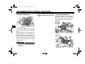
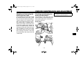
Traction control system
1. Brake pedal
The traction control system helps maintain traction when accelerating. If sensors detect that the rear wheel is
starting to slip (uncontrolled spinning),
the traction control system assists by
regulating engine power as needed until traction is restored. The traction control system indicator/warning light
flashes to let the rider know that traction
control has engaged.
1
4
EWA15431
The brake pedal is on the right side of
the motorcycle. To apply the rear
brake, press down on the brake pedal.
4-18
WARNING
The traction control system is not a
substitute for riding appropriately
for the conditions. Traction control
cannot prevent loss of traction due
to excessive speed when entering
turns, when accelerating hard at a
sharp lean angle, or while braking,
and cannot prevent front wheel slipping. As with any motorcycle, approach surfaces that may be
slippery with caution and avoid especially slippery surfaces.
U1KB11E0.book Page 19 Monday, August 8, 2011 11:14 AM
INSTRUMENT AND CONTROL FUNCTIONS
●
TIP
●
●
The traction control may engage
when the vehicle travels over a
bump.
The rider may notice slight changes in engine and exhaust sounds
when the traction control system is
engaged.
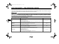
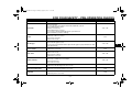
There are six traction control system
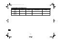
modes and an off mode.
Display
OFF
TCS OFF
Mode 1
TCS
Mode 2
TCS
Mode 3
TCS
Mode 4
TCS
Mode 5
TCS
“TCS” modes 2 through 6 provide
for more traction control system
assist. Mode 6 provides the most
traction control system assist.
● “TCS OFF” mode turns the traction
control system off. The system
may also be automatically disabled in some riding conditions
(see “Resetting” on page 4-20).
When the key is turned to “ON”, the
traction control system is enabled and
the last mode selected displays in the
multi-function meter.
All traction control system modes can
be selected when the key is in the “ON”
position. Modes 1 through 6 can also
be selected when the vehicle is moving,
however the throttle grip must be completely closed. The traction control system cannot be turned on or off while the
vehicle is moving.
ECA16800
Mode 6
●
TCS
“TCS” mode 1 provides for the
least traction control system assist.
NOTICE
Use only the specified tires. (See
page 7-20.) Using different sized
tires will prevent the traction control
system from controlling tire rotation
accurately.
4-19
Setting the traction control system
EWA16070
WARNING
Changing settings while riding can
distract the operator. Therefore, take
extra precaution when changing
modes while riding.
When the vehicle is stopped, push the
upper side of the traction control system switch for at least two seconds to
turn the traction control system off.
Push the lower side of the switch to turn
the traction control system on.
When the vehicle is stopped or while
riding, close the throttle and push the
lower side of the switch to change from
modes 1 to 6. Close the throttle and
push the upper side of the switch to
change from modes 6 to 1.
TIP
The vehicle was set to “TCS” mode 6 at
the time of manufacture.
4
U1KB11E0.book Page 20 Monday, August 8, 2011 11:14 AM
INSTRUMENT AND CONTROL FUNCTIONS
1
4
1. Traction control system mode display
1
1. Traction control system switch “TCS”
Resetting
The traction control system may be disabled in the following conditions:
● Either the front wheel or rear wheel
comes off the ground while riding
● Excessive rear wheel spinning
If the traction control system has been
disabled, both the traction control system indicator/warning light and the engine trouble warning light come on.
To reset the traction control system:
Turn the key to “OFF”. Wait at least one
second, then turn the key back to “ON”.
The traction control system indicator/warning light should go off and the
system will be enabled. The engine
trouble warning light should go off after
the motorcycle reaches at least 20
km/h (12 mi/h). If the traction control
system indicator/warning light and/or
engine trouble warning light still remain
on after resetting, the motorcycle may
still be ridden; however, have a
Yamaha dealer check the motorcycle
as soon as possible.
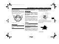
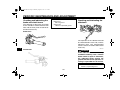
ECA17731
NOTICE
●
Keep any type of magnets (including magnetic pick-up tools,
magnetic screwdrivers, etc.)
away from the front wheel sensor or rotor; otherwise, the sensor or rotor may be damaged,
4-20
●
resulting in improper performance of the traction control
system.
Be careful not to damage the
sensor or rotor.
1
2
1. Front wheel sensor rotor
2. Front wheel sensor
U1KB11E0.book Page 21 Monday, August 8, 2011 11:14 AM
INSTRUMENT AND CONTROL FUNCTIONS
EAU13074
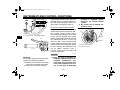
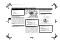
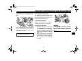
Fuel tank cap
EAU13221
TIP
The fuel tank cap cannot be closed unless the key is in the lock. In addition,
the key cannot be removed if the cap is
not properly closed and locked.
EWA11091
WARNING
Make sure that the fuel tank cap is
properly closed after filling fuel.
Leaking fuel is a fire hazard.
1. Fuel tank cap lock cover
2. Unlock.
Fuel
Make sure there is sufficient gasoline in
the tank.
EWA10881
WARNING
Gasoline and gasoline vapors are
extremely flammable. To avoid fires
and explosions and to reduce the
risk of injury when refueling, follow
these instructions.
1. Before refueling, turn off the engine and be sure that no one is sitting on the vehicle. Never refuel
while smoking, or while in the vicinity of sparks, open flames, or
other sources of ignition such as
the pilot lights of water heaters and
clothes dryers.
2. Do not overfill the fuel tank. When
refueling, be sure to insert the
pump nozzle into the fuel tank filler
hole. Stop filling when the fuel
reaches the bottom of the filler
tube. Because fuel expands when
it heats up, heat from the engine or
the sun can cause fuel to spill out
of the fuel tank.
To open the fuel tank cap
Open the fuel tank cap lock cover, insert the key into the lock, and then turn
it 1/4 turn clockwise. The lock will be released and the fuel tank cap can be
opened.
To close the fuel tank cap
1. Push the fuel tank cap into position
with the key inserted in the lock.
2. Turn the key counterclockwise to
the original position, remove it, and
then close the lock cover.
4-21
4
U1KB11E0.book Page 22 Monday, August 8, 2011 11:14 AM
INSTRUMENT AND CONTROL FUNCTIONS
ately. If gasoline spills on your skin,
wash with soap and water. If gasoline spills on your clothing, change
your clothes.
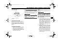
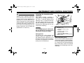
1
2
EAU13382
4
1. Fuel tank filler tube
2. Maximum fuel level
3. Wipe up any spilled fuel immediately. NOTICE: Immediately wipe
off spilled fuel with a clean, dry,
soft cloth, since fuel may deteriorate painted surfaces or plastic
parts. [ECA10071]
4. Be sure to securely close the fuel
tank cap.
EWA15151
WARNING
Gasoline is poisonous and can
cause injury or death. Handle gasoline with care. Never siphon gasoline by mouth. If you should swallow
some gasoline or inhale a lot of gasoline vapor, or get some gasoline in
your eyes, see your doctor immedi-
Recommended fuel:
Premium unleaded gasoline only
Fuel tank capacity:
18.0 L (4.76 US gal, 3.96 Imp.gal)
Fuel reserve amount (when the fuel
level warning light comes on):
3.1 L (0.82 US gal, 0.68 Imp.gal)
ECA11400
NOTICE
Use only unleaded gasoline. The use
of leaded gasoline will cause severe
damage to internal engine parts,
such as the valves and piston rings,
as well as to the exhaust system.
Your Yamaha engine has been designed to use premium unleaded gasoline with a pump octane number
[(R+M)/2] of 91 or higher, or a research
octane number of 95 or higher. If
knocking (or pinging) occurs, use a
4-22
gasoline of a different brand. Use of unleaded fuel will extend spark plug life
and reduce maintenance costs.
Gasohol
There are two types of gasohol: gasohol containing ethanol and that containing methanol. Gasohol containing
ethanol can be used if the ethanol content does not exceed 10% (E10). Gasohol containing methanol is not
recommended by Yamaha because it
can cause damage to the fuel system
or vehicle performance problems.
U1KB11E0.book Page 23 Monday, August 8, 2011 11:14 AM
INSTRUMENT AND CONTROL FUNCTIONS
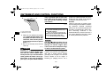
EAU51140
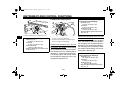
Fuel tank breather hose and
overflow hose
EAU13433
NOTICE
This model is equipped with a catalytic
converter in the exhaust system.
Use only unleaded gasoline. The use
of leaded gasoline will cause unrepairable damage to the catalytic
converter.
EWA10862
WARNING
2
1
1. Fuel tank breather hose
2. Fuel tank overflow hose
TIP
For California: See page 7-12 for
breather hose information.
Before operating the motorcycle:
● Check each hose connection.
● Check each hose for cracks or
damage, and replace if damaged.
● Make sure that the end of each
hose is not blocked, and clean if
necessary.
● Make sure that the end of each
hose is positioned outside of the
cowling.
ECA10701
Catalytic converter
The exhaust system is hot after operation. To prevent a fire hazard or
burns:
● Do not park the vehicle near
possible fire hazards such as
grass or other materials that
easily burn.
● Park the vehicle in a place
where pedestrians or children
are not likely to touch the hot
exhaust system.
● Make sure that the exhaust system has cooled down before doing any maintenance work.
● Do not allow the engine to idle
more than a few minutes. Long
idling can cause a build-up of
heat.
4-23
4
U1KB11E0.book Page 24 Monday, August 8, 2011 11:14 AM
INSTRUMENT AND CONTROL FUNCTIONS
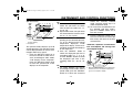
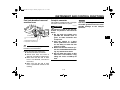
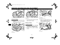
EAU47271
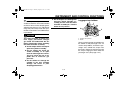
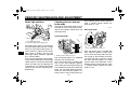
Seats
1
Passenger seat
4
1
2
1
2
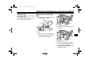
To remove the passenger seat
1. Insert the key into the seat lock,
and then turn it clockwise.
1. Projection
2. Seat holder
1. Bolt
1
2. Remove the key.
Rider seat
1. Seat lock
2. Unlock.
2. Lift the front of the passenger seat
and pull it forward.
To install the passenger seat
1. Insert the projection on the rear of
the passenger seat into the seat
holder as shown, and then push
the front of the seat down to lock it
in place.
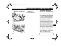
To remove the rider seat
1. Remove the passenger seat.
2. Pull up the corners on the rear of
the rider seat as shown, remove
the bolts with the hexagon wrench
located on the bottom of the passenger seat, and then pull the seat
off.
4-24
2
1. Passenger seat
2. Hexagon wrench
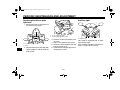
To install the rider seat
1. Insert the projections into the seat
holders as shown, then place the
seat in the original position.
U1KB11E0.book Page 25 Monday, August 8, 2011 11:14 AM
INSTRUMENT AND CONTROL FUNCTIONS
EAU47530
Helmet holder
1
1
1
2
1. Projection
2. Seat holder
1. Helmet holder
2. Install the bolts with the hexagon
wrench.
3. Insert the hexagon wrench back
into its holder on the passenger
seat.
4. Install the passenger seat.
TIP
Make sure that the seats are properly
secured before riding.
The helmet holder is located on the bottom of the passenger seat.
To secure a helmet to the helmet
holder
1. Remove the passenger seat. (See
page 4-24.)
2. Attach the helmet to the helmet
holder, and then securely install
the passenger seat. WARNING!
Never ride with a helmet attached to the helmet holder,
since the helmet may hit objects, causing loss of control
and possibly an accident. [EWA10161]
4-25
To release the helmet from the helmet holder
Remove the passenger seat, remove
the helmet from the helmet holder, and
then install the seat.
4
U1KB11E0.book Page 26 Monday, August 8, 2011 11:14 AM
INSTRUMENT AND CONTROL FUNCTIONS
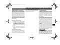
EAU14463
Storage compartment
●
Do not exceed the maximum
load of 189 kg (417 lb) for the vehicle.
1
EAU47442
Rider footrest position
The rider footrests can be adjusted to
one of two positions to suit the rider’s
preference. Have a Yamaha dealer adjust the position of the rider footrests.
Left side
4
1. Storage compartment
The storage compartment is located
under the passenger seat. (See page
4-24.)
When storing the Owner’s Manual or
other documents in the storage compartment, be sure to wrap them in a
plastic bag so that they will not get wet.
When washing the vehicle, be careful
not to let any water enter the storage
compartment.
1
1. Rider footrest
Right side
EWA10961
WARNING
●
1
Do not exceed the load limit of 1
kg (2 lb) for the storage compartment.
1. Rider footrest
4-26
U1KB11E0.book Page 27 Monday, August 8, 2011 11:14 AM
INSTRUMENT AND CONTROL FUNCTIONS
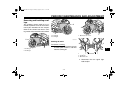
EAU47260
Rear view mirrors
The rear view mirrors of this vehicle can
be folded forward for parking in narrow
spaces. Fold the mirrors back to their
original position before riding.
1
1
2
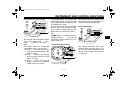
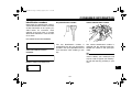
EAU47621
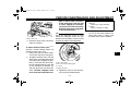
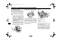
Adjusting the front fork
EWA14670
WARNING
Always adjust the spring preload on
both fork legs equally, otherwise
poor handling and loss of stability
may result.
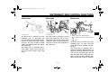
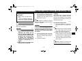
Each front fork leg is equipped with a
spring preload adjusting bolt, the right
front fork leg is equipped with a rebound damping force adjusting screw
and the left front fork leg with a compression damping force adjusting
screw.
2
1. Riding position
2. Parking position
ECA10101
NOTICE
EWA14371
WARNING
Be sure to fold the rear view mirrors
back to their original position before
riding.
load
and
thereby
soften
the
suspension, turn the adjusting bolt on
each fork leg in direction (b).
1
4
1. Spring preload adjusting bolt
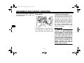
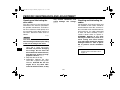
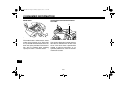
Align the appropriate groove on the adjusting mechanism with the top of the
front fork collar.
To avoid damaging the mechanism,
do not attempt to turn beyond the
maximum or minimum settings.
Spring preload
To increase the spring preload and
thereby harden the suspension, turn
the adjusting bolt on each fork leg in direction (a). To decrease the spring pre-
0
1
2
1. Current setting
2. Front fork collar
4-27
1
2
3
4
5
U1KB11E0.book Page 28 Monday, August 8, 2011 11:14 AM
INSTRUMENT AND CONTROL FUNCTIONS
Spring preload setting:
Minimum (soft):
0
Standard:
2
Maximum (hard):
5
4
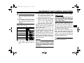
Rebound damping force
The rebound damping force is adjusted
on the right front fork leg only. To increase the rebound damping force and
thereby harden the rebound damping,
turn the adjusting screw in direction (a).
To decrease the rebound damping
force and thereby soften the rebound
damping, turn the adjusting screw in direction (b).
TIP
Be sure to perform this adjustment on
the right front fork leg.
(b)
1
(a)
pression damping force and thereby
soften the compression damping, turn
the adjusting screw in direction (b).
TIP
Be sure to perform this adjustment on
the left front fork leg.
1
1. Rebound damping force adjusting screw
Rebound damping setting:
Minimum (soft):
25 click(s) in direction (b)*
Standard:
12 click(s) in direction (b)*
Maximum (hard):
1 click(s) in direction (b)*
* With the adjusting screw fully turned
in direction (a)
Compression damping force
The compression damping force is adjusted on the left front fork leg only. To
increase the compression damping
force and thereby harden the compression damping, turn the adjusting screw
in direction (a). To decrease the com-
4-28
1. Compression damping force adjusting screw
Compression damping setting:
Minimum (soft):
25 click(s) in direction (b)*
Standard:
20 click(s) in direction (b)*
Maximum (hard):
1 click(s) in direction (b)*
* With the adjusting screw fully turned
in direction (a)
U1KB11E0.book Page 29 Monday, August 8, 2011 11:14 AM
INSTRUMENT AND CONTROL FUNCTIONS
EAU51890
TIP
Although the total number of clicks of a
damping force adjusting mechanism
may not exactly match the above specifications due to small differences in
production, the actual number of clicks
always represents the entire adjusting
range. To obtain a precise adjustment,
it would be advisable to check the number of clicks of each damping force adjusting mechanism and to modify the
specifications as necessary.
Adjusting the shock absorber
assembly
This shock absorber assembly is
equipped with a spring preload adjusting screw, a rebound damping force
adjusting screw, a compression damping force adjusting bolt (for fast compression damping) and a compression
damping force adjusting bolt (for slow
compression damping).
1
(a)
(b)
1. Spring preload adjusting screw
ECA10101
NOTICE
To avoid damaging the mechanism,
do not attempt to turn beyond the
maximum or minimum settings.
Spring preload
To increase the spring preload and
thereby harden the suspension, turn
the adjusting screw in direction (a). To
decrease the spring preload and thereby soften the suspension, turn the adjusting screw in direction (b).
4-29
Spring preload setting:
Minimum (soft):
16 turn(s) in direction (b)*
Standard:
8 turn(s) in direction (b)*
Maximum (hard):
0 turn(s) in direction (b)*
* With the adjusting screw fully turned
in direction (a)
Rebound damping force
To increase the rebound damping force
and thereby harden the rebound damping, turn the adjusting screw in direction
(a). To decrease the rebound damping
force and thereby soften the rebound
damping, turn the adjusting screw in direction (b).
4
U1KB11E0.book Page 30 Monday, August 8, 2011 11:14 AM
INSTRUMENT AND CONTROL FUNCTIONS
Compression damping force
(a)
(a)
1
(b)
4
1
2
(b)
Compression damping setting (for
fast compression damping):
Minimum (soft):
4 turn(s) in direction (b)*
Standard:
3 turn(s) in direction (b)*
Maximum (hard):
0 turn(s) in direction (b)*
* With the adjusting bolt fully turned in
direction (a)
1. Rebound damping force adjusting screw
Rebound damping setting:
Minimum (soft):
20 click(s) in direction (b)*
Standard:
15 click(s) in direction (b)*
Maximum (hard):
3 click(s) in direction (b)*
* With the adjusting screw fully turned
in direction (a)
1. Compression damping force adjusting bolt
(for fast compression damping)
2. Compression damping force adjusting bolt
(for slow compression damping)
Compression damping force (for fast
compression damping)
To increase the compression damping
force and thereby harden the compression damping, turn the adjusting bolt in
direction (a). To decrease the compression damping force and thereby soften
the compression damping, turn the adjusting bolt in direction (b).
4-30
Compression damping force (for slow
compression damping)
To increase the compression damping
force and thereby harden the compression damping, turn the adjusting bolt in
direction (a). To decrease the compression damping force and thereby soften
the compression damping, turn the adjusting bolt in direction (b).
Compression damping setting (for
slow compression damping):
Minimum (soft):
20 click(s) in direction (b)*
Standard:
9 click(s) in direction (b)*
Maximum (hard):
1 click(s) in direction (b)*
* With the adjusting bolt fully turned in
direction (a)
U1KB11E0.book Page 31 Monday, August 8, 2011 11:14 AM
INSTRUMENT AND CONTROL FUNCTIONS
TIP
To obtain a precise adjustment, it is advisable to check the actual total number
of clicks or turns of each damping force
adjusting mechanism. This adjustment
range may not exactly match the specifications listed due to small differences
in production.
●
Do not dispose of a damaged or
worn-out shock absorber assembly yourself. Take the shock
absorber assembly to a Yamaha
dealer for any service.
EAU15181
Luggage strap holders
1
2
2
EWA10221
WARNING
1
This shock absorber assembly contains highly pressurized nitrogen
gas. Read and understand the following information before handling
the shock absorber assembly.
● Do not tamper with or attempt to
open the cylinder assembly.
● Do not subject the shock absorber assembly to an open
flame or other high heat source.
This may cause the unit to explode due to excessive gas
pressure.
● Do not deform or damage the
cylinder in any way. Cylinder
damage will result in poor
damping performance.
1. Luggage strap holder
2. Hook
There are four luggage strap holders on
the bottom of the passenger seat. To
use the strap holders, remove the passenger seat, unhook the straps from
the hooks, and then install the seat with
the straps hanging out from under the
passenger seat. (See page 4-24.)
4-31
4
U1KB11E0.book Page 32 Monday, August 8, 2011 11:14 AM
INSTRUMENT AND CONTROL FUNCTIONS
EAU15305
Sidestand
The sidestand is located on the left side
of the frame. Raise the sidestand or
lower it with your foot while holding the
vehicle upright.
4
this system regularly and have a
Yamaha dealer repair it if it does not
function properly.
TIP
The built-in sidestand switch is part of
the ignition circuit cut-off system, which
cuts the ignition in certain situations.
(See the following section for an explanation of the ignition circuit cut-off system.)
EWA10241
WARNING
The vehicle must not be ridden with
the sidestand down, or if the sidestand cannot be properly moved up
(or does not stay up), otherwise the
sidestand could contact the ground
and distract the operator, resulting
in a possible loss of control.
Yamaha’s ignition circuit cut-off
system has been designed to assist
the operator in fulfilling the responsibility of raising the sidestand before starting off. Therefore, check
4-32
EAU44892
Ignition circuit cut-off system
The ignition circuit cut-off system (comprising the sidestand switch, clutch
switch and neutral switch) has the following functions.
● It prevents starting when the transmission is in gear and the sidestand is up, but the clutch lever is
not pulled.
● It prevents starting when the transmission is in gear and the clutch lever is pulled, but the sidestand is
still down.
● It cuts the running engine when the
transmission is in gear and the
sidestand is moved down.
Periodically check the operation of the
ignition circuit cut-off system according
to the following procedure.
U1KB11E0.book Page 33 Monday, August 8, 2011 11:14 AM
INSTRUMENT AND CONTROL FUNCTIONS
With the engine turned off:
1. Move the sidestand down.
2. Make sure that the engine stop switch is set to “
3. Turn the key on.
4. Shift the transmission into the neutral position.
5. Push the start switch.
Does the engine start?
YES
WARNING
If a malfunction is noted, have a Yamaha
dealer check the system before riding.
”.
The neutral switch may not be working correctly.
The motorcycle should not be ridden until
checked by a Yamaha dealer.
NO
With the engine still running:
6. Move the sidestand up.
7. Keep the clutch lever pulled.
8. Shift the transmission into gear.
9. Move the sidestand down.
Does the engine stall?
YES
NO
The sidestand switch may not be working correctly.
The motorcycle should not be ridden until
checked by a Yamaha dealer.
NO
The clutch switch may not be working correctly.
The motorcycle should not be ridden until
checked by a Yamaha dealer.
After the engine has stalled:
10. Move the sidestand up.
11. Keep the clutch lever pulled.
12. Push the start switch.
Does the engine start?
YES
The system is OK. The motorcycle can be ridden.
4-33
4
U1KB11E0.book Page 1 Monday, August 8, 2011 11:14 AM
FOR YOUR SAFETY – PRE-OPERATION CHECKS
EAU15596
Inspect your vehicle each time you use it to make sure the vehicle is in safe operating condition. Always follow the inspection
and maintenance procedures and schedules described in the Owner’s Manual.
EWA11151
WARNING
Failure to inspect or maintain the vehicle properly increases the possibility of an accident or equipment damage.
Do not operate the vehicle if you find any problem. If a problem cannot be corrected by the procedures provided in
this manual, have the vehicle inspected by a Yamaha dealer.
Before using this vehicle, check the following points:
ITEM
5
Fuel
CHECKS
•
•
•
•
Check fuel level in fuel tank.
Refuel if necessary.
Check fuel line for leakage.
Check fuel tank breather hose and overflow hose for obstructions, cracks or damage, and check hose connections.
PAGE
4-21, 4-23
Engine oil
• Check oil level in engine.
• If necessary, add recommended oil to specified level.
• Check vehicle for oil leakage.
7-13
Coolant
• Check coolant level in reservoir.
• If necessary, add recommended coolant to specified level.
• Check cooling system for leakage.
7-15
Front brake
•
•
•
•
•
•
•
Check operation.
If soft or spongy, have Yamaha dealer bleed hydraulic system.
Check brake pads for wear.
Replace if necessary.
Check fluid level in reservoir.
If necessary, add specified brake fluid to specified level.
Check hydraulic system for leakage.
5-1
7-24, 7-25
U1KB11E0.book Page 2 Monday, August 8, 2011 11:14 AM
FOR YOUR SAFETY – PRE-OPERATION CHECKS
ITEM
CHECKS
PAGE
Rear brake
•
•
•
•
•
•
•
Check operation.
If soft or spongy, have Yamaha dealer bleed hydraulic system.
Check brake pads for wear.
Replace if necessary.
Check fluid level in reservoir.
If necessary, add specified brake fluid to specified level.
Check hydraulic system for leakage.
Clutch
•
•
•
•
Check operation.
Lubricate cable if necessary.
Check lever free play.
Adjust if necessary.
Throttle grip
• Make sure that operation is smooth.
• Check throttle grip free play.
• If necessary, have Yamaha dealer adjust throttle grip free play and lubricate cable
and grip housing.
Control cables
• Make sure that operation is smooth.
• Lubricate if necessary.
Drive chain
•
•
•
•
Check chain slack.
Adjust if necessary.
Check chain condition.
Lubricate if necessary.
7-26, 7-28
Wheels and tires
•
•
•
•
Check for damage.
Check tire condition and tread depth.
Check air pressure.
Correct if necessary.
7-20, 7-22
Brake and shift pedals
• Make sure that operation is smooth.
• Lubricate pedal pivoting points if necessary.
7-29
Brake and clutch levers
• Make sure that operation is smooth.
• Lubricate lever pivoting points if necessary.
7-30
Sidestand
• Make sure that operation is smooth.
• Lubricate pivot if necessary.
7-30
7-24, 7-25
7-22
7-19, 7-29
7-28
5-2
5
U1KB11E0.book Page 3 Monday, August 8, 2011 11:14 AM
FOR YOUR SAFETY – PRE-OPERATION CHECKS
ITEM
CHECKS
PAGE
Chassis fasteners
• Make sure that all nuts, bolts and screws are properly tightened.
• Tighten if necessary.
—
Instruments, lights, signals
and switches
• Check operation.
• Correct if necessary.
—
Sidestand switch
• Check operation of ignition circuit cut-off system.
• If system is not working correctly, have Yamaha dealer check vehicle.
5
5-3
4-32
U1KB11E0.book Page 1 Monday, August 8, 2011 11:14 AM
OPERATION AND IMPORTANT RIDING POINTS
EAU15951
EAU48710
EAU51870
Starting the engine
Read the Owner’s Manual carefully to
become familiar with all controls. If
there is a control or function you do not
understand, ask your Yamaha dealer.
EWA10271
WARNING
Failure to familiarize yourself with
the controls can lead to loss of control, which could cause an accident
or injury.
TIP
This model is equipped with:
● a lean angle sensor to stop the engine in case of a turnover. In this
case, the multi-function display indicates error code 30, but this is
not a malfunction. Turn the key to
“OFF” and then to “ON” to clear the
error code. Failing to do so will prevent the engine from starting even
though the engine will crank when
pushing the start switch.
● an engine auto-stop system. The
engine stops automatically if left
idling for 20 minutes. If the engine
stops, simply push the start switch
to restart the engine.
6-1
In order for the ignition circuit cut-off
system to enable starting, one of the
following conditions must be met:
● The transmission is in the neutral
position.
● The transmission is in gear with
the clutch lever pulled and the
sidestand up.
See page 4-32 for more information.
1. Turn the key to “ON” and make
sure that the engine stop switch is
set to “ ”.
The following warning lights and
indicator light should come on for a
few seconds, then go off.
● Oil level warning light
● Fuel level warning light
● Coolant temperature warning
light
● Shift timing indicator light
● Engine trouble warning light
● Traction control system indicator/warning light
6
U1KB11E0.book Page 2 Monday, August 8, 2011 11:14 AM
OPERATION AND IMPORTANT RIDING POINTS
ECA11833
If a warning or indicator light does
not come on initially when the key is
turned to “ON”, or if a warning or indicator light remains on, see page
4-3 for the corresponding warning
and indicator light circuit check.
6
EAU16671
Shifting
NOTICE
2. Shift the transmission into the neutral position. The neutral indicator
light should come on. If not, ask a
Yamaha dealer to check the electrical circuit.
3. Start the engine by pushing the
start switch.
If the engine fails to start, release
the start switch, wait a few seconds, and then try again. Each
starting attempt should be as short
as possible to preserve the battery. Do not crank the engine more
than 10 seconds on any one attempt.
ECA11042
NOTICE
ECA10260
NOTICE
6
5
4
3
2
N
1
1
●
2
1. Shift pedal
2. Neutral position
●
Shifting gears lets you control the
amount of engine power available for
starting off, accelerating, climbing hills,
etc.
The gear positions are shown in the illustration.
Even with the transmission in
the neutral position, do not
coast for long periods of time
with the engine off, and do not
tow the motorcycle for long distances. The transmission is
properly lubricated only when
the engine is running. Inadequate lubrication may damage
the transmission.
Always use the clutch while
changing gears to avoid damaging the engine, transmission,
and drive train, which are not
designed to withstand the
shock of forced shifting.
EAU16681
TIP
To shift the transmission into the neutral position, press the shift pedal down
repeatedly until it reaches the end of its
travel, and then slightly raise it.
For maximum engine life, never accelerate hard when the engine is
cold!
6-2
To start out and accelerate
1. Pull the clutch lever to disengage
the clutch.
2. Shift the transmission into first
gear. The neutral indicator light
should go out.
3. Open the throttle gradually, and at
the same time, release the clutch
lever slowly.
U1KB11E0.book Page 3 Monday, August 8, 2011 11:14 AM
OPERATION AND IMPORTANT RIDING POINTS
4. At the recommended shift points
shown in the following table, close
the throttle, and at the same time,
quickly pull the clutch lever in.
5. Shift the transmission into second
gear. (Make sure not to shift the
transmission into the neutral position.)
6. Open the throttle part way and
gradually release the clutch lever.
7. Follow the same procedure when
shifting to the next higher gear.
TIP
When shifting gears in normal operating conditions, use the recommended
shift points.
EAU16700
To decelerate
1. Apply both the front and the rear
brakes to slow the motorcycle.
2. Shift the transmission into first
gear when the motorcycle reaches
25 km/h (16 mi/h). If the engine is
about to stall or runs very roughly,
pull the clutch lever in and use the
brakes to stop the motorcycle.
3. Shift the transmission into the neutral position when the motorcycle
is almost completely stopped. The
neutral indicator light should come
on.
EAU16740
Recommended shift points
The recommended shift points during
acceleration and deceleration are
shown in the table below.
Shift up points:
1st → 2nd: 20 km/h (12 mi/h)
2nd → 3rd: 30 km/h (19 mi/h)
3rd → 4th: 40 km/h (25 mi/h)
4th → 5th: 50 km/h (31 mi/h)
5th → 6th: 60 km/h (37 mi/h)
Shift down points:
6th → 5th: 25 km/h (16 mi/h)
5th → 4th: 25 km/h (16 mi/h)
4th → 3rd: 25 km/h (16 mi/h)
3rd → 2nd: 25 km/h (16 mi/h)
2nd → 1st: —
EAU16841
Engine break-in
There is never a more important period
in the life of your engine than the period
between 0 and 1600 km (1000 mi). For
this reason, you should read the following material carefully.
Since the engine is brand new, do not
put an excessive load on it for the first
1600 km (1000 mi). The various parts in
the engine wear and polish themselves
to the correct operating clearances.
During this period, prolonged full-throttle operation or any condition that might
result in engine overheating must be
avoided.
EAU17083
0–1000 km (0–600 mi)
Avoid prolonged operation above 6900
r/min. NOTICE: After 1000 km (600
mi) of operation, the engine oil must
be changed and the oil filter cartridge or element replaced. [ECA10302]
1000–1600 km (600–1000 mi)
Avoid prolonged operation above 8300
r/min.
6-3
6
U1KB11E0.book Page 4 Monday, August 8, 2011 11:14 AM
OPERATION AND IMPORTANT RIDING POINTS
1600 km (1000 mi) and beyond
The vehicle can now be operated normally.
ECA10310
NOTICE
●
●
6
Keep the engine speed out of
the tachometer red zone.
If any engine trouble should occur during the engine break-in
period, immediately have a
Yamaha dealer check the vehicle.
TIP
During and after the engine break-in
period, the exhaust heat may cause
discoloration of the exhaust pipe, but
this is normal.
EAU17213
Parking
When parking, stop the engine, and
then remove the key from the main
switch.
EWA10311
WARNING
●
●
●
Since the engine and exhaust
system can become very hot,
park in a place where pedestrians or children are not likely to
touch them and be burned.
Do not park on a slope or on soft
ground, otherwise the vehicle
may overturn, increasing the
risk of a fuel leak and fire.
Do not park near grass or other
flammable materials which
might catch fire.
6-4
U1KB11E0.book Page 1 Monday, August 8, 2011 11:14 AM
PERIODIC MAINTENANCE AND ADJUSTMENT
EAU17244
EWA15122
EAU17302
WARNING
Periodic inspection, adjustment, and lubrication will keep your vehicle in the
safest and most efficient condition possible. Safety is an obligation of the vehicle owner/operator. The most important
points of vehicle inspection, adjustment, and lubrication are explained on
the following pages.
The intervals given in the periodic
maintenance charts should be simply
considered as a general guide under
normal riding conditions. However, depending on the weather, terrain, geographical location, and individual use,
the maintenance intervals may need to
be shortened.
Turn off the engine when performing
maintenance
unless
otherwise
specified.
● A running engine has moving
parts that can catch on body
parts or clothing and electrical
parts that can cause shocks or
fires.
● Running the engine while servicing can lead to eye injury,
burns, fire, or carbon monoxide
poisoning – possibly leading to
death. See page 2-2 for more information about carbon monoxide.
EWA15460
EWA10321
WARNING
Failure to properly maintain the vehicle or performing maintenance activities incorrectly may increase
your risk of injury or death during
service or while using the vehicle. If
you are not familiar with vehicle service, have a Yamaha dealer perform
service.
WARNING
Brake discs, calipers, drums, and
linings can become very hot during
use. To avoid possible burns, let
brake components cool before
touching them.
7-1
Emission controls not only function to
ensure cleaner air, but are also vital to
proper engine operation and maximum
performance. In the following periodic
maintenance charts, the services related to emissions control are grouped
separately. These services require
specialized data, knowledge, and
equipment. Maintenance, replacement,
or repair of the emission control devices and systems may be performed by
any repair establishment or individual
that is certified (if applicable). Yamaha
dealers are trained and equipped to
perform these particular services.
7
U1KB11E0.book Page 2 Monday, August 8, 2011 11:14 AM
PERIODIC MAINTENANCE AND ADJUSTMENT
EAU17361
Owner’s tool kit
1
1. Owner’s tool kit
7
The owner’s tool kit is located under the
rider seat. (See page 4-24.)
The service information included in this
manual and the tools provided in the
owner’s tool kit are intended to assist
you in the performance of preventive
maintenance and minor repairs. However, additional tools such as a torque
wrench may be necessary to perform
certain maintenance work correctly.
TIP
If you do not have the tools or experience required for a particular job, have
a Yamaha dealer perform it for you.
7-2
U1KB11E0.book Page 3 Monday, August 8, 2011 11:14 AM
PERIODIC MAINTENANCE AND ADJUSTMENT
EAU48490
TIP
●
●
From 24000 mi (37000 km) or 36 months, repeat the maintenance intervals starting from 8000 mi (13000 km) or 12
months.
Items marked with an asterisk require special tools, data and technical skills, have a Yamaha dealer perform the service.
EAU17601
Periodic maintenance chart for the emission control system
INITIAL
No.
ITEM
ROUTINE
600 mi
(1000 km)
or
1 month
ODOMETER READINGS
4000 mi
(7000 km)
or
6 months
8000 mi
12000 mi
16000 mi
20000 mi
(13000 km) (19000 km) (25000 km) (31000 km)
or
or
or
or
12 months 18 months 24 months 30 months
Fuel line
• Check fuel hoses for cracks or
damage.
• Replace if necessary.
√
√
√
√
√
2 *
Spark plugs
• Check condition.
• Adjust gap and clean.
• Replace every 8000 mi (13000
km) or 12 months.
√
Replace.
√
Replace.
√
3 *
Valve clearance
• Check and adjust valve clearance
when engine is cold.
4 *
Crankcase breather
system
• Check breather hose for cracks or
damage.
• Replace if necessary.
√
√
√
√
√
5 *
Fuel injection
• Adjust synchronization.
√
√
√
√
√
6 *
Exhaust system
• Check for leakage.
• Tighten if necessary.
• Replace gasket(s) if necessary.
√
√
√
√
√
1 *
Every 26600 mi (42000 km)
7-3
7
U1KB11E0.book Page 4 Monday, August 8, 2011 11:14 AM
PERIODIC MAINTENANCE AND ADJUSTMENT
INITIAL
ROUTINE
600 mi
(1000 km)
or
1 month
ODOMETER READINGS
4000 mi
(7000 km)
or
6 months
8000 mi
12000 mi
16000 mi
20000 mi
(13000 km) (19000 km) (25000 km) (31000 km)
or
or
or
or
12 months 18 months 24 months 30 months
No.
ITEM
7 *
Evaporative emission control system
(for California only)
• Check control system for damage.
• Replace if necessary.
√
√
8 *
Air induction system
• Check the air cut-off valve, reed
valve, and hose for damage.
• Replace any damaged parts if
necessary.
√
√
7
7-4
U1KB11E0.book Page 5 Monday, August 8, 2011 11:14 AM
PERIODIC MAINTENANCE AND ADJUSTMENT
EAU32186
General maintenance and lubrication chart
INITIAL
No.
ITEM
ROUTINE
600 mi
(1000 km)
or
1 month
ODOMETER READINGS
4000 mi
(7000 km)
or
6 months
8000 mi
12000 mi
16000 mi
20000 mi
(13000 km) (19000 km) (25000 km) (31000 km)
or
or
or
or
12 months 18 months 24 months 30 months
1 *
Air filter element
• Replace.
2 *
Clutch
• Check operation.
• Adjust or replace cable.
√
√
√
√
√
√
3 *
Front brake
• Check operation, fluid level, and
for fluid leakage.
• Replace brake pads if necessary.
√
√
√
√
√
√
4 *
Rear brake
• Check operation, fluid level, and
for fluid leakage.
• Replace brake pads if necessary.
√
√
√
√
√
√
√
√
√
√
√
5 *
Brake hoses
Every 24000 mi (37000 km)
• Check for cracks or damage.
• Check for correct routing and
clamping.
7
• Replace.
Every 4 years
Wheels
• Check runout and for damage.
• Replace if necessary.
√
√
√
√
√
7 *
Tires
• Check tread depth and for damage.
• Replace if necessary.
• Check air pressure.
• Correct if necessary.
√
√
√
√
√
8 *
Wheel bearings
• Check bearings for smooth operation.
• Replace if necessary.
√
√
√
√
√
6 *
7-5
U1KB11E0.book Page 6 Monday, August 8, 2011 11:14 AM
PERIODIC MAINTENANCE AND ADJUSTMENT
INITIAL
No.
9 *
10
11 *
7
ITEM
Swingarm pivot
bearings
Drive chain
Steering bearings
ROUTINE
600 mi
(1000 km)
or
1 month
• Check operation and for excessive play.
ODOMETER READINGS
4000 mi
(7000 km)
or
6 months
√
• Moderately repack with lithiumsoap-based grease.
• Check chain slack, alignment and
condition.
• Adjust and lubricate chain with a
special O-ring chain lubricant
thoroughly.
• Check bearing assemblies for
looseness.
8000 mi
12000 mi
16000 mi
20000 mi
(13000 km) (19000 km) (25000 km) (31000 km)
or
or
or
or
12 months 18 months 24 months 30 months
√
√
√
√
Every 32000 mi (50000 km)
Every 500 mi (800 km) and after washing the motorcycle, riding in the rain or
riding in wet areas
√
√
• Moderately repack with lithiumsoap-based grease.
√
√
√
√
Every 16000 mi (25000 km)
12 *
Steering damper
• Check operation and for oil leakage.
√
√
√
√
√
13 *
Chassis fasteners
• Check all chassis fitting and fasteners.
• Correct if necessary.
√
√
√
√
√
14
Brake lever pivot
shaft
• Apply silicone grease lightly.
√
√
√
√
√
15
Brake pedal pivot
shaft
• Apply lithium-soap-based grease
lightly.
√
√
√
√
√
16
Clutch lever pivot
shaft
• Apply lithium-soap-based grease
lightly.
√
√
√
√
√
17
Shift pedal pivot
shaft
• Apply lithium-soap-based grease
lightly.
√
√
√
√
√
7-6
U1KB11E0.book Page 7 Monday, August 8, 2011 11:14 AM
PERIODIC MAINTENANCE AND ADJUSTMENT
INITIAL
No.
ITEM
ROUTINE
18
Sidestand pivot
• Check operation.
• Apply lithium-soap-based grease
lightly.
19 *
Sidestand switch
• Check operation and replace if
necessary.
20 *
Front fork
21 *
600 mi
(1000 km)
or
1 month
ODOMETER READINGS
4000 mi
(7000 km)
or
6 months
8000 mi
12000 mi
16000 mi
20000 mi
(13000 km) (19000 km) (25000 km) (31000 km)
or
or
or
or
12 months 18 months 24 months 30 months
√
√
√
√
√
√
√
√
√
√
• Check operation and for oil leakage.
• Replace if necessary.
√
√
√
√
√
Shock absorber assembly
• Check operation and for oil leakage.
• Replace if necessary.
√
√
√
√
√
22 *
Rear suspension
link pivots
• Check operation.
• Correct if necessary.
23
Engine oil
• Change (warm engine before
draining).
√
24 *
Engine oil filter cartridge
• Replace.
√
25 *
Cooling system
√
√
• Check hoses for cracks or damage.
• Replace if necessary.
√
√
√
√
√
√
√
√
√
√
√
• Change with ethylene glycol antifreeze coolant every 24 months.
√
√
Change.
26 *
Front and rear brake
switches
• Check operation.
√
√
√
√
√
√
27 *
Control cables
• Apply Yamaha chain and cable
lube or engine oil thoroughly.
√
√
√
√
√
√
7-7
7
U1KB11E0.book Page 8 Monday, August 8, 2011 11:14 AM
PERIODIC MAINTENANCE AND ADJUSTMENT
INITIAL
No.
ITEM
ROUTINE
28 *
Throttle grip
• Check operation.
• Check throttle grip free play, and
adjust if necessary.
• Lubricate cable and grip housing.
29 *
Lights, signals and
switches
• Check operation.
• Adjust headlight beam.
600 mi
(1000 km)
or
1 month
√
ODOMETER READINGS
4000 mi
(7000 km)
or
6 months
8000 mi
12000 mi
16000 mi
20000 mi
(13000 km) (19000 km) (25000 km) (31000 km)
or
or
or
or
12 months 18 months 24 months 30 months
√
√
√
√
√
√
√
√
√
√
EAU17650
TIP
●
7
●
Air filter
• This model’s air filter is equipped with a disposable oil-coated paper element, which must not be cleaned with compressed air to avoid damaging it.
• The air filter element needs to be replaced more frequently when riding in unusually wet or dusty areas.
Hydraulic brake service
• After disassembling the brake master cylinders and calipers, always change the fluid. Regularly check the brake fluid
levels and fill the reservoirs as required.
• Every two years replace the internal components of the brake master cylinders and calipers, and change the brake
fluid.
• Replace the brake hoses every four years and if cracked or damaged.
7-8
U1KB11E0.book Page 9 Monday, August 8, 2011 11:14 AM
PERIODIC MAINTENANCE AND ADJUSTMENT
EAU18781
Removing and installing cowlings
The cowlings shown need to be removed to perform some of the maintenance jobs described in this chapter.
Refer to this section each time a cowling needs to be removed and installed.
1
2
1
1
1. Cowling B
2. Cowling D
1. Quick fastener screw
1
2
1. Cowling A
2. Cowling C
EAU47252
Cowlings A and B
To remove a cowling
1. Remove the quick fastener screws
and the quick fasteners, and then
take the cowling off.
2
1
3
3
1. Cowling A
2. Cowling B
3. Quick fastener
2. Disconnect the turn signal light
lead coupler.
7-9
7
U1KB11E0.book Page 10 Monday, August 8, 2011 11:14 AM
PERIODIC MAINTENANCE AND ADJUSTMENT
1
2
1
2
2
1
1. Turn signal light lead coupler
1. Slot
2. Projection
To install a cowling
1. Connect the turn signal light lead
coupler.
2. Fit the projections on the cowling
into the slots as shown.
7
1
1. Cowling C
2. Quick fastener screw
3. Install the quick fasteners and the
quick fastener screws.
3. Slide the cowling forward to unhook its projection from the slot,
and then pull the cowling off.
EAU47243
Cowlings C and D
1
To remove a cowling
1. Remove cowling A (if removing
cowling C) or cowling B (if removing cowling D). (See page 7-9.)
2. Remove the quick fastener
screws.
2
2
1. Slot
2. Projection
1. Slot
2. Projection
7-10
U1KB11E0.book Page 11 Monday, August 8, 2011 11:14 AM
PERIODIC MAINTENANCE AND ADJUSTMENT
To install a cowling
1. Insert the projection into the slot,
and then slide the cowling backward.
2. Place the cowling in its original position, and then install the quick
fastener screws.
3. Install cowling A or B.
2
3
1
1. Cowling C
2. Slot
3. Projection
2
3
1
1. Cowling D
2. Slot
3. Projection
EAU19652
Checking the spark plugs
The spark plugs are important engine
components, which should be checked
periodically, preferably by a Yamaha
dealer. Since heat and deposits will
cause any spark plug to slowly erode,
they should be removed and checked
in accordance with the periodic maintenance and lubrication chart. In addition,
the condition of the spark plugs can reveal the condition of the engine.
The porcelain insulator around the center electrode of each spark plug should
be a medium-to-light tan (the ideal color
when the vehicle is ridden normally),
and all spark plugs installed in the engine should have the same color. If any
spark plug shows a distinctly different
color, the engine could be operating improperly. Do not attempt to diagnose
such problems yourself. Instead, have
a Yamaha dealer check the vehicle.
If a spark plug shows signs of electrode
erosion and excessive carbon or other
deposits, it should be replaced.
Specified spark plug:
NGK/LMAR9E-J
7-11
7
U1KB11E0.book Page 12 Monday, August 8, 2011 11:14 AM
PERIODIC MAINTENANCE AND ADJUSTMENT
EAU19681
#4
Canister (for California only)
FUEL TANK ATMOSPHERE
#3
TIP
If a torque wrench is not available when
installing a spark plug, a good estimate
of the correct torque is 1/4–1/2 turn
past finger tight. However, the spark
plug should be tightened to the specified torque as soon as possible.
#2
Before installing a spark plug, the spark
plug gap should be measured with a
wire thickness gauge and, if necessary,
adjusted to specification.
#1
ECA10840
NOTICE
1 1
1. Spark plug gap
Spark plug gap:
0.6–0.7 mm (0.024–0.028 in)
7
Clean the surface of the spark plug
gasket and its mating surface, and then
wipe off any grime from the spark plug
threads.
Do not use any tools to remove or install the spark plug cap, otherwise
the ignition coil coupler may get
damaged. The spark plug cap may
be difficult to remove because the
rubber seal on the end of the cap fits
tightly. To remove the spark plug
cap, simply twist it back and forth
while pulling it out; to install it, twist
it back and forth while pushing it in.
Tightening torque:
Spark plug:
13 Nm (1.3 m·kgf, 9.4 ft·lbf)
7-12
CHARCOAL
THROTTLE BODY CANISTER
This model is equipped with a canister
to prevent the discharging of fuel vapor
into the atmosphere. Before operating
this vehicle, make sure to check the following:
● Check each hose connection.
● Check each hose and canister for
cracks or damage. Replace if damaged.
● Make sure that the canister breather is not blocked, and if necessary,
clean it.
U1KB11E0.book Page 13 Monday, August 8, 2011 11:14 AM
PERIODIC MAINTENANCE AND ADJUSTMENT
4. Remove the engine oil filler cap,
the engine oil drain bolt and its
gasket to drain the oil from the
crankcase.
EAU47281
Engine oil and oil filter cartridge
4
The engine oil level should be checked
before each ride. In addition, the oil
must be changed and the oil filter cartridge replaced at the intervals specified in the periodic maintenance and
lubrication chart.
To check the engine oil level
1. Place the vehicle on a level surface and hold it in an upright position. A slight tilt to the side can
result in a false reading.
2. Start the engine, warm it up for
several minutes, and then turn it
off.
3. Wait a few minutes until the oil settles, and then check the oil level
through the check window located
at the bottom-right side of the
crankcase.
TIP
The engine oil should be between the
minimum and maximum level marks.
2
3
1
1.
2.
3.
4.
2
Engine oil level check window
Maximum level mark
Minimum level mark
Engine oil filler cap
4. If the engine oil is at or below the
minimum level mark, add sufficient
oil of the recommended type to
raise it to the correct level.
To change the engine oil (with or
without oil filter cartridge replacement)
1. Remove cowlings C and D. (See
page 7-9.)
2. Start the engine, warm it up for
several minutes, and then turn it
off.
3. Place an oil pan under the engine
to collect the used oil.
7-13
1
1. Engine oil drain bolt
2. Gasket
TIP
Skip steps 5–7 if the oil filter cartridge is
not being replaced.
5. Remove the oil filter cartridge with
an oil filter wrench.
7
U1KB11E0.book Page 14 Monday, August 8, 2011 11:14 AM
PERIODIC MAINTENANCE AND ADJUSTMENT
1
2
1. Oil filter cartridge
2. Oil filter wrench
TIP
An oil filter wrench is available at a
Yamaha dealer.
7
6. Apply a thin coat of clean engine
oil to the O-ring of the new oil filter
cartridge.
1
1. O-ring
1. Torque wrench
TIP
Make sure that the O-ring is properly
seated.
7. Install the new oil filter cartridge
with an oil filter wrench, and then
tighten it to the specified torque
with a torque wrench.
Tightening torque:
Oil filter cartridge:
17 Nm (1.7 m·kgf, 12 ft·lbf)
8. Install the engine oil drain bolt and
its new gasket, and then tighten
the bolt to the specified torque.
Tightening torque:
Engine oil drain bolt:
43 Nm (4.3 m·kgf, 31 ft·lbf)
9. Refill with the specified amount of
the recommended engine oil, and
then install and tighten the oil filler
cap.
7-14
U1KB11E0.book Page 15 Monday, August 8, 2011 11:14 AM
PERIODIC MAINTENANCE AND ADJUSTMENT
Recommended engine oil:
See page 9-1.
Oil quantity:
Without oil filter cartridge replacement:
3.73 L (3.94 US qt, 3.28 Imp.qt)
With oil filter cartridge replacement:
3.93 L (4.15 US qt, 3.46 Imp.qt)
TIP
Be sure to wipe off spilled oil on any
parts after the engine and exhaust system have cooled down.
ECA11620
NOTICE
●
●
In order to prevent clutch slippage (since the engine oil also
lubricates the clutch), do not
mix any chemical additives. Do
not use oils with a diesel specification of “CD” or oils of a higher quality than specified. In
addition, do not use oils labeled
“ENERGY CONSERVING II” or
higher.
Make sure that no foreign material enters the crankcase.
10. Start the engine, and then let it idle
for several minutes while checking
it for oil leakage. If oil is leaking, immediately turn the engine off and
check for the cause.
TIP
After the engine is started, the engine
oil level warning light should go off if the
oil level is sufficient.
ECA10401
NOTICE
If the oil level warning light flickers
or remains on even if the oil level is
correct, immediately turn the engine
off and have a Yamaha dealer check
the vehicle.
11. Turn the engine off, wait a few minutes until the oil settles, and then
check the oil level and correct it if
necessary.
12. Install the cowlings.
EAU20070
Coolant
The coolant level should be checked
before each ride. In addition, the coolant must be changed at the intervals
specified in the periodic maintenance
and lubrication chart.
EAU38173
To check the coolant level
1. Place the vehicle on a level surface and hold it in an upright position.
TIP
●
●
The coolant level must be checked
on a cold engine since the level
varies with engine temperature.
Make sure that the vehicle is positioned straight up when checking
the coolant level. A slight tilt to the
side can result in a false reading.
2. Check the coolant level in the coolant reservoir.
TIP
The coolant should be between the
minimum and maximum level marks.
7-15
7
U1KB11E0.book Page 16 Monday, August 8, 2011 11:14 AM
PERIODIC MAINTENANCE AND ADJUSTMENT
1
2
3
1. Coolant reservoir
2. Maximum level mark
3. Minimum level mark
7
3. If the coolant is at or below the
minimum level mark, remove the
coolant reservoir cover by removing the bolts, remove the coolant
reservoir cap, and then add coolant to the maximum level mark.
WARNING! Remove only the
coolant reservoir cap. Never attempt to remove the radiator
cap when the engine is hot.
[EWA15161] NOTICE: If coolant is not
available, use distilled water or
soft tap water instead. Do not
use hard water or salt water
since it is harmful to the engine.
If water has been used instead
of coolant, replace it with coolant as soon as possible, otherwise the cooling system will not
be protected against frost and
corrosion. If water has been
added to the coolant, have a
Yamaha dealer check the antifreeze content of the coolant as
soon as possible, otherwise the
effectiveness of the coolant will
be reduced. [ECA10472]
1
1
1. Coolant reservoir cap
Coolant reservoir capacity (up to
the maximum level mark):
0.25 L (0.26 US qt, 0.22 Imp.qt)
4. Install the reservoir cap, and then
install the coolant reservoir cover
by installing the bolts.
EAU47303
2
1. Coolant reservoir cover
2. Bolt
7-16
To change the coolant
1. Place the vehicle on a level surface and let the engine cool if necessary.
2. Remove cowlings B and C. (See
page 7-9.)
3. Place a container under the engine
to collect the used coolant.
U1KB11E0.book Page 17 Monday, August 8, 2011 11:14 AM
PERIODIC MAINTENANCE AND ADJUSTMENT
4. Remove
the
radiator
cap.
WARNING! Never attempt to remove the radiator cap when the
engine is hot. [EWA10381]
6. Remove the coolant reservoir cover by removing the bolts, and then
remove the coolant reservoir cap.
1
7. Remove the coolant reservoir by
removing the bolts, and then turn
the reservoir upside down to empty it.
1
1
2
2
1. Coolant reservoir cover
2. Bolt
1. Radiator cap
5. Remove the coolant drain bolt and
its gasket to drain the cooling system.
1. Coolant reservoir
2. Bolt
1
2
1. Coolant reservoir cap
1
1. Coolant drain bolt
2. Gasket
7-17
8. After the coolant is completely
drained, thoroughly flush the cooling system with clean tap water.
9. Install the coolant reservoir by installing the bolts.
10. Install the coolant drain bolt and its
new gasket, and then tighten the
bolt to the specified torque.
Tightening torque:
Coolant drain bolt:
7 Nm (0.7 m·kgf, 5.1 ft·lbf)
7
U1KB11E0.book Page 18 Monday, August 8, 2011 11:14 AM
PERIODIC MAINTENANCE AND ADJUSTMENT
11. Pour the recommended coolant
into the reservoir to the maximum
level mark, and then install the
coolant reservoir cap.
12. Pour the recommended coolant
into the radiator until it is full.
7
15. Start the engine, and then check
the vehicle for coolant leakage. If
coolant is leaking, have a Yamaha
dealer check the cooling system.
16. Install the coolant reservoir cover
by installing the bolts.
17. Install the cowlings.
Antifreeze/water mixture ratio:
1:1
Recommended antifreeze:
High-quality ethylene glycol antifreeze containing corrosion inhibitors for aluminum engines
Coolant quantity:
Radiator capacity (including all
routes):
2.73 L (2.89 US qt, 2.40 Imp.qt)
Coolant reservoir capacity (up to the
maximum level mark):
0.25 L (0.26 US qt, 0.22 Imp.qt)
13. Install the radiator cap, start the
engine, let it idle for several minutes, and then turn it off.
14. Remove the radiator cap to check
the coolant level in the radiator. If
necessary, add sufficient coolant
until it reaches the top of the radiator, and then install the radiator
cap.
7-18
EAU36764
Air filter element
The air filter element must be replaced
at the intervals specified in the periodic
maintenance and lubrication chart.
Have a Yamaha dealer replace the air
filter element.
U1KB11E0.book Page 19 Monday, August 8, 2011 11:14 AM
PERIODIC MAINTENANCE AND ADJUSTMENT
EAU44734
Checking the engine idling
speed
EAU21384
Checking the throttle grip free
play
Check the engine idling speed and, if
necessary, have it corrected by a
Yamaha dealer.
Engine idling speed:
1150–1250 r/min
1
EAU21401
Valve clearance
The valve clearance changes with use,
resulting in improper air-fuel mixture
and/or engine noise. To prevent this
from occurring, the valve clearance
must be adjusted by a Yamaha dealer
at the intervals specified in the periodic
maintenance and lubrication chart.
1. Throttle grip free play
The throttle grip free play should measure 3.0–5.0 mm (0.12–0.20 in) at the
inner edge of the throttle grip. Periodically check the throttle grip free play
and, if necessary, have a Yamaha dealer adjust it.
7-19
7
U1KB11E0.book Page 20 Monday, August 8, 2011 11:14 AM
PERIODIC MAINTENANCE AND ADJUSTMENT
EAU21755
Tires
To maximize the performance, durability, and safe operation of your motorcycle, note the following points regarding
the specified tires.
Tire air pressure
The tire air pressure should be checked
and, if necessary, adjusted before each
ride.
EWA10503
WARNING
7
Operation of this vehicle with improper tire pressure may cause severe injury or death from loss of
control.
● The tire air pressure must be
checked and adjusted on cold
tires (i.e., when the temperature
of the tires equals the ambient
temperature).
● The tire air pressure must be adjusted in accordance with the
riding speed and with the total
weight of rider, passenger, cargo, and accessories approved
for this model.
Tire air pressure (measured on cold
tires):
0–90 kg (0–198 lb):
Front:
250 kPa (2.50 kgf/cm², 36 psi)
Rear:
290 kPa (2.90 kgf/cm², 42 psi)
90–189 kg (198–417 lb):
Front:
250 kPa (2.50 kgf/cm², 36 psi)
Rear:
290 kPa (2.90 kgf/cm², 42 psi)
High-speed riding:
Front:
250 kPa (2.50 kgf/cm², 36 psi)
Rear:
290 kPa (2.90 kgf/cm², 42 psi)
Maximum load*:
189 kg (417 lb)
* Total weight of rider, passenger, cargo and accessories
EWA10511
WARNING
Never overload your vehicle. Operation of an overloaded vehicle could
cause an accident.
7-20
Tire inspection
1. Tire sidewall
2. Tire wear indicator
3. Tire tread depth
Always check the tires before operating
the motorcycle. If a tire tread shows
crosswise lines (minimum tread depth),
if the tire has a nail or glass fragments
in it, or if the sidewall is cracked, contact a Yamaha dealer immediately and
have the tire replaced.
Minimum tire tread depth (front and
rear):
1.0 mm (0.04 in)
U1KB11E0.book Page 21 Monday, August 8, 2011 11:14 AM
PERIODIC MAINTENANCE AND ADJUSTMENT
EWA10581
●
Tire information
WARNING
●
●
●
It is dangerous to ride with a
worn-out tire. When a tire tread
begins to show crosswise lines,
have a Yamaha dealer replace
the tire immediately.
The replacement of all wheeland brake-related parts, including the tires, should be left to a
Yamaha dealer, who has the
necessary professional knowledge and experience to do so.
Ride at moderate speeds after
changing a tire since the tire
surface must first be “broken
in” for it to develop its optimal
characteristics.
Use only the tire valves and
valve cores listed below to
avoid tire deflation during a
high-speed ride.
After extensive tests, only the tires listed below have been approved for this
model by Yamaha Motor Co., Ltd.
1. Tire air valve
2. Tire air valve core
3. Tire air valve cap with seal
This motorcycle is equipped with tubeless tires, tire air valves and cast
wheels.
EWA10481
WARNING
●
●
The front and rear tires should
be of the same make and design, otherwise the handling
characteristics of the motorcycle may be different, which
could lead to an accident.
Always make sure that the valve
caps are securely installed to
prevent air pressure leakage.
7-21
Front tire:
Size:
120/70 ZR17M/C (58W)
Manufacturer/model:
DUNLOP/Qualifier II
Rear tire:
Size:
190/55 ZR17M/C (75W)
Manufacturer/model:
DUNLOP/Qualifier II
FRONT and REAR:
Tire air valve:
TR412
Valve core:
#9100 (original)
7
EWA10600
WARNING
This motorcycle is fitted with superhigh-speed tires. Note the following
points in order to make the most efficient use of these tires.
U1KB11E0.book Page 22 Monday, August 8, 2011 11:14 AM
PERIODIC MAINTENANCE AND ADJUSTMENT
●
●
●
●
7
Use only the specified replacement tires. Other tires may run
the danger of bursting at super
high speeds.
Brand-new tires can have a relatively poor grip on certain road
surfaces until they have been
“broken in”. Therefore, it is advisable before doing any highspeed riding to ride conservatively for approximately 100 km
(60 mi) after installing a new tire.
The tires must be warmed up
before a high-speed run.
Always adjust the tire air pressure according to the operating
conditions.
EAU21962
Cast wheels
To maximize the performance, durability, and safe operation of your vehicle,
note the following points regarding the
specified wheels.
● The wheel rims should be checked
for cracks, bends, warpage or other damage before each ride. If any
damage is found, have a Yamaha
dealer replace the wheel. Do not
attempt even the smallest repair to
the wheel. A deformed or cracked
wheel must be replaced.
● The wheel should be balanced
whenever either the tire or wheel
has been changed or replaced. An
unbalanced wheel can result in
poor performance, adverse handling characteristics, and a shortened tire life.
7-22
EAU33891
Adjusting the clutch lever free
play
1. Clutch lever free play adjusting bolt
2. Clutch lever free play
The clutch lever free play should measure 10.0–15.0 mm (0.39–0.59 in) as
shown. Periodically check the clutch lever free play and, if necessary, adjust it
as follows.
To increase the clutch lever free play,
turn the clutch lever free play adjusting
bolt at the clutch lever in direction (a).
To decrease the clutch lever free play,
turn the adjusting bolt in direction (b).
U1KB11E0.book Page 23 Monday, August 8, 2011 11:14 AM
PERIODIC MAINTENANCE AND ADJUSTMENT
EAU37913
TIP
If the specified clutch lever free play
cannot be obtained as described
above, proceed as follows.
Checking the brake lever free
play
1. Fully turn the adjusting bolt at the
clutch lever in direction (a) to loosen the clutch cable.
2. Loosen the locknut at the crankcase.
3. To increase the clutch lever free
play, turn the clutch lever free play
adjusting nut in direction (a). To
decrease the clutch lever free play,
turn the adjusting nut in direction
(b).
1
1. No brake lever free play
There should be no free play at the
brake lever end. If there is free play,
have a Yamaha dealer inspect the
brake system.
EWA14211
1 2
WARNING
(b)
(a)
1. Locknut
2. Clutch lever free play adjusting nut
braking performance, which may result in loss of control and an accident.
A soft or spongy feeling in the brake
lever can indicate the presence of air
in the hydraulic system. If there is air
in the hydraulic system, have a
Yamaha dealer bleed the system before operating the vehicle. Air in the
hydraulic system will diminish the
4. Tighten the locknut.
7-23
7
U1KB11E0.book Page 24 Monday, August 8, 2011 11:14 AM
PERIODIC MAINTENANCE AND ADJUSTMENT
Checking the front and rear
brake pads
wear indicator groove almost appears,
have a Yamaha dealer replace the
brake pads as a set.
The front and rear brake pads must be
checked for wear at the intervals specified in the periodic maintenance and
lubrication chart.
Rear brake pads
EAU22273
Brake light switches
1
2
(a)
(b)
EAU22392
EAU46291
EAU43062
Front brake pads
1
1
1. Rear brake light switch
2. Rear brake light switch adjusting nut
7
The brake light, which is activated by
the brake pedal and brake lever, should
come on just before braking takes effect. If necessary, adjust the rear brake
light switch as follows, but the front
brake light switch should be adjusted
by a Yamaha dealer.
Turn the rear brake light switch adjusting nut while holding the rear brake light
switch in place. To make the brake light
come on earlier, turn the adjusting nut
in direction (a). To make the brake light
come on later, turn the adjusting nut in
direction (b).
1
1
1. Brake pad wear indicator groove
The front brake calipers are equipped
with two sets of brake pads.
Each front brake pad is provided with
one or two wear indicator grooves,
which allow you to check the brake pad
wear without having to disassemble the
brake. To check the brake pad wear,
check the wear indicator grooves. If a
brake pad has worn to the point that a
7-24
1. Brake pad wear indicator groove
Each rear brake pad is provided with
wear indicator grooves, which allow
you to check the brake pad wear without having to disassemble the brake.
To check the brake pad wear, check
the wear indicator grooves. If a brake
pad has worn to the point that a wear
indicator groove almost appears, have
a Yamaha dealer replace the brake
pads as a set.
U1KB11E0.book Page 25 Monday, August 8, 2011 11:14 AM
PERIODIC MAINTENANCE AND ADJUSTMENT
EAU22581
Checking the brake fluid level
Before riding, check that the brake fluid
is above the minimum level mark.
Check the brake fluid level with the top
of the reservoir level. Replenish the
brake fluid if necessary.
●
Rear brake
●
1
Front brake
●
1. Minimum level mark
UPPER
1
LOWER
Specified brake fluid:
DOT 4
Use only the specified brake fluid; otherwise, the rubber seals
may deteriorate, causing leakage.
Refill with the same type of
brake fluid. Adding a brake fluid
other than DOT 4 may result in a
harmful chemical reaction.
Be careful that water does not
enter the brake fluid reservoir
when refilling. Water will significantly lower the boiling point of
the fluid and may result in vapor
lock.
ECA17640
EWA15990
NOTICE
WARNING
1. Minimum level mark
Improper maintenance can result in
loss of braking ability. Observe
these precautions:
● Insufficient brake fluid may allow air to enter the brake system,
reducing
braking
performance.
● Clean the filler cap before removing. Use only DOT 4 brake
fluid from a sealed container.
7-25
Brake fluid may damage painted surfaces or plastic parts. Always clean
up spilled fluid immediately.
As the brake pads wear, it is normal for
the brake fluid level to gradually go
down. A low brake fluid level may indicate worn brake pads and/or brake system leakage; therefore, be sure to
check the brake pads for wear and the
brake system for leakage. If the brake
7
U1KB11E0.book Page 26 Monday, August 8, 2011 11:14 AM
PERIODIC MAINTENANCE AND ADJUSTMENT
fluid level goes down suddenly, have a
Yamaha dealer check the cause before
further riding.
EAU22731
EAU22760
Changing the brake fluid
Drive chain slack
Have a Yamaha dealer change the
brake fluid at the intervals specified in
the TIP after the periodic maintenance
and lubrication chart. In addition, have
the oil seals of the master cylinders and
calipers as well as the brake hoses replaced at the intervals listed below or
whenever they are damaged or leaking.
● Oil seals: Replace every two
years.
● Brake hoses: Replace every four
years.
The drive chain slack should be
checked before each ride and adjusted
if necessary.
7
EAU22774
To check the drive chain slack
1. Place the motorcycle on the sidestand.
TIP
When checking and adjusting the drive
chain slack, there should be no weight
on the motorcycle.
2. Shift the transmission into the neutral position.
3. Measure the drive chain slack as
shown.
Drive chain slack:
25.0–35.0 mm (0.98–1.38 in)
7-26
U1KB11E0.book Page 27 Monday, August 8, 2011 11:14 AM
PERIODIC MAINTENANCE AND ADJUSTMENT
gine as well as other vital parts
of the motorcycle and can lead
to chain slippage or breakage.
To prevent this from occurring,
keep the drive chain slack within the specified limits. [ECA10571]
1
1. Drive chain slack
4. If the drive chain slack is incorrect,
adjust it as follows.
TIP
Using the alignment marks on each
side of the swingarm, make sure that
both drive chain pullers are in the same
position for proper wheel alignment.
EAU34317
To adjust the drive chain slack
Consult a Yamaha dealer before adjusting the drive chain slack.
1. Loosen the axle nut and the locknut on each side of the swingarm.
2. To tighten the drive chain, turn the
drive chain slack adjusting bolt on
each side of the swingarm in direction (a). To loosen the drive chain,
turn the adjusting bolt on each side
of the swingarm in direction (b),
and then push the rear wheel forward. NOTICE: Improper drive
chain slack will overload the en-
Tightening torques:
Axle nut:
150 Nm (15 m·kgf, 108 ft·lbf)
Locknut:
16 Nm (1.6 m·kgf, 12 ft·lbf)
4. Make sure that the drive chain pullers are in the same position, the
drive chain slack is correct, and
the drive chain moves smoothly.
1 2 3 4
(a)
(b)
5
1.
2.
3.
4.
5.
Axle nut
Drive chain puller
Drive chain slack adjusting bolt
Locknut
Alignment marks
3. Tighten the axle nut, then the locknuts to their specified torques.
7-27
7
U1KB11E0.book Page 28 Monday, August 8, 2011 11:14 AM
PERIODIC MAINTENANCE AND ADJUSTMENT
EAU23025
Cleaning and lubricating the
drive chain
may contain substances that
could damage the O-rings.
[ECA11111]
The drive chain must be cleaned and
lubricated at the intervals specified in
the periodic maintenance and lubrication chart, otherwise it will quickly wear
out, especially when riding in dusty or
wet areas. Service the drive chain as
follows.
The operation of all control cables and
the condition of the cables should be
checked before each ride, and the cables and cable ends should be lubricated if necessary. If a cable is damaged
or does not move smoothly, have a
Yamaha dealer check or replace it.
WARNING! Damage to the outer
housing of cables may result in internal rusting and cause interference with cable movement. Replace
damaged cables as soon as possible to prevent unsafe conditions.
ECA10583
NOTICE
The drive chain must be lubricated
after washing the motorcycle, riding
in the rain or riding in wet areas.
7
EAU23095
Checking and lubricating the
cables
1. Clean the drive chain with kerosene and a small soft brush.
NOTICE: To prevent damaging
the O-rings, do not clean the
drive chain with steam cleaners,
high-pressure washers or inappropriate solvents. [ECA11121]
2. Wipe the drive chain dry.
3. Thoroughly lubricate the drive
chain with a special O-ring chain
lubricant. NOTICE: Do not use
engine oil or any other lubricants for the drive chain, as they
[EWA10711]
Recommended lubricant:
Yamaha Chain and Cable Lube or
engine oil
7-28
U1KB11E0.book Page 29 Monday, August 8, 2011 11:14 AM
PERIODIC MAINTENANCE AND ADJUSTMENT
EAU23114
EAU44273
Checking and lubricating the
throttle grip and cable
Checking and lubricating the
brake and shift pedals
The operation of the throttle grip should
be checked before each ride. In addition, the cable should be lubricated by a
Yamaha dealer at the intervals specified in the periodic maintenance chart.
The throttle cable is equipped with a
rubber cover. Make sure that the cover
is securely installed. Even though the
cover is installed correctly, it does not
completely protect the cable from water
entry. Therefore, use care not to pour
water directly onto the cover or cable
when washing the vehicle. If the cable
or cover becomes dirty, wipe clean with
a moist cloth.
The operation of the brake and shift
pedals should be checked before each
ride, and the pedal pivots should be lubricated if necessary.
Recommended lubricant:
Lithium-soap-based grease
Brake pedal
7
Shift pedal
7-29
U1KB11E0.book Page 30 Monday, August 8, 2011 11:14 AM
PERIODIC MAINTENANCE AND ADJUSTMENT
EAU23143
Checking and lubricating the
brake and clutch levers
The operation of the brake and clutch
levers should be checked before each
ride, and the lever pivots should be lubricated if necessary.
EAU23202
Recommended lubricants:
Brake lever:
Silicone grease
Clutch lever:
Lithium-soap-based grease
Checking and lubricating the
sidestand
Brake lever
7
The operation of the sidestand should
be checked before each ride, and the
sidestand pivot and metal-to-metal
contact surfaces should be lubricated if
necessary.
EWA10731
Clutch lever
WARNING
If the sidestand does not move up
and down smoothly, have a Yamaha
dealer check or repair it. Otherwise,
the sidestand could contact the
ground and distract the operator, resulting in a possible loss of control.
Recommended lubricant:
Lithium-soap-based grease
7-30
U1KB11E0.book Page 31 Monday, August 8, 2011 11:14 AM
PERIODIC MAINTENANCE AND ADJUSTMENT
EAUM1652
Lubricating the swingarm pivots
EAU23272
Checking the front fork
The condition and operation of the front
fork must be checked as follows at the
intervals specified in the periodic maintenance and lubrication chart.
To check the condition
Check the inner tubes for scratches,
damage and excessive oil leakage.
ECA10590
The swingarm pivots must be lubricated by a Yamaha dealer at the intervals
specified in the periodic maintenance
and lubrication chart.
Recommended lubricant:
Lithium-soap-based grease
To check the operation
1. Place the vehicle on a level surface and hold it in an upright position. WARNING! To avoid injury,
securely support the vehicle so
there is no danger of it falling
over. [EWA10751]
2. While applying the front brake,
push down hard on the handlebars
several times to check if the front
fork compresses and rebounds
smoothly.
7-31
NOTICE
If any damage is found or the front
fork does not operate smoothly,
have a Yamaha dealer check or repair it.
7
U1KB11E0.book Page 32 Monday, August 8, 2011 11:14 AM
PERIODIC MAINTENANCE AND ADJUSTMENT
EAU23283
Checking the steering
7
Worn or loose steering bearings may
cause danger. Therefore, the operation
of the steering must be checked as follows at the intervals specified in the periodic maintenance and lubrication
chart.
1. Place a stand under the engine to
raise the front wheel off the
ground. (See page 7-39 for more
information.)
WARNING!
To
avoid injury, securely support
the vehicle so there is no danger
of it falling over. [EWA10751]
2. Hold the lower ends of the front
fork legs and try to move them forward and backward. If any free
play can be felt, have a Yamaha
dealer check or repair the steering.
EAU23291
Checking the wheel bearings
EAU51960
Battery
2
1
3
2
4
6 5
The front and rear wheel bearings must
be checked at the intervals specified in
the periodic maintenance and lubrication chart. If there is play in the wheel
hub or if the wheel does not turn
smoothly, have a Yamaha dealer check
the wheel bearings.
7-32
1.
2.
3.
4.
5.
6.
Bolt
Quick fastener screw
Positive battery lead (red)
Battery cover
Battery
Negative battery lead (black)
The battery is located under the rider
seat. (See page 4-24.)
This model is equipped with a VRLA
(Valve Regulated Lead Acid) battery.
There is no need to check the electrolyte or to add distilled water. However,
the battery lead connections need to be
checked and, if necessary, tightened.
U1KB11E0.book Page 33 Monday, August 8, 2011 11:14 AM
PERIODIC MAINTENANCE AND ADJUSTMENT
EWA10760
WARNING
●
●
Electrolyte is poisonous and
dangerous since it contains sulfuric acid, which causes severe
burns. Avoid any contact with
skin, eyes or clothing and always shield your eyes when
working near batteries. In case
of contact, administer the following FIRST AID.
• EXTERNAL: Flush with plenty
of water.
• INTERNAL: Drink large quantities of water or milk and immediately call a physician.
• EYES: Flush with water for 15
minutes and seek prompt
medical attention.
Batteries produce explosive hydrogen gas. Therefore, keep
sparks, flames, cigarettes, etc.,
away from the battery and provide sufficient ventilation when
charging it in an enclosed
space.
●
KEEP THIS AND ALL BATTERIES OUT OF THE REACH OF
CHILDREN.
EWA16090
WARNING
Remove the battery cover by removing the bolts and the quick fastener
screws before servicing the battery.
The cover material can conduct
electricity. If the cover has not been
removed, touching the cover and the
battery positive terminal at the same
time with a tool will cause a short circuit and sparks.
To charge the battery
Have a Yamaha dealer charge the battery as soon as possible if it seems to
have discharged. Keep in mind that the
battery tends to discharge more quickly
if the vehicle is equipped with optional
electrical accessories.
7-33
ECA16521
NOTICE
To charge a VRLA (Valve Regulated
Lead Acid) battery, a special (constant-voltage) battery charger is required. Using a conventional battery
charger will damage the battery.
To store the battery
1. If the vehicle will not be used for
more than one month, remove the
battery, fully charge it, and then
place it in a cool, dry place.
NOTICE: When removing the
battery, be sure the key is
turned to “OFF”, then disconnect the negative lead before
disconnecting the positive lead.
[ECA16302]
2. If the battery will be stored for more
than two months, check it at least
once a month and fully charge it if
necessary.
3. Fully charge the battery before installation. NOTICE: When installing the battery, be sure the key
is turned to “OFF”, then con-
7
U1KB11E0.book Page 34 Monday, August 8, 2011 11:14 AM
PERIODIC MAINTENANCE AND ADJUSTMENT
nect the positive lead before
connecting the negative lead.
[ECA16840]
4. After installation, make sure that
the battery leads are properly connected to the battery terminals.
ECA16530
EAU49823
Replacing the fuses
NOTICE
3
Always keep the battery charged.
Storing a discharged battery can
cause permanent battery damage.
7
7
8
9
The main fuse, the fuel injection system
fuse, and the fuse boxes, which contain
the fuses for the individual circuits, are
located under the rider seat. (See page
4-24.)
1
1.
2.
3.
4.
2
Fuel injection system fuse
Fuel injection system spare fuse
Fuse box
Main fuse
7-34
7
4
654 3 2 1
1.
2.
3.
4.
5.
6.
7.
8.
9.
Ignition fuse
Signaling system fuse
Electronic throttle valve fuse
Backup fuse (for clock)
Right radiator fan fuse
Left radiator fan fuse
Spare fuse
Steering damper fuse
Headlight fuse
TIP
To access the fuel injection system
fuse, remove the starter relay cover by
pulling it upward.
U1KB11E0.book Page 35 Monday, August 8, 2011 11:14 AM
PERIODIC MAINTENANCE AND ADJUSTMENT
EAU39013
2
3
1
1. Starter relay cover
2. Fuel injection system fuse
3. Fuel injection system spare fuse
If a fuse is blown, replace it as follows.
1. Turn the key to “OFF” and turn off
the electrical circuit in question.
2. Remove the blown fuse, and then
install a new fuse of the specified
amperage. WARNING! Do not
use a fuse of a higher amperage
rating than recommended to
avoid causing extensive damage to the electrical system and
possibly a fire. [EWA15131]
Specified fuses:
Main fuse:
50.0 A
Headlight fuse:
20.0 A
Signaling system fuse:
10.0 A
Ignition fuse:
15.0 A
Radiator fan fuse:
10.0 A × 2
Steering damper fuse:
7.5 A
Fuel injection system fuse:
15.0 A
Backup fuse:
7.5 A
Electronic throttle valve fuse:
7.5 A
3. Turn the key to “ON” and turn on
the electrical circuit in question to
check if the device operates.
4. If the fuse immediately blows
again, have a Yamaha dealer
check the electrical system.
7-35
Replacing a headlight bulb
This model is equipped with halogen
bulb headlights. If a headlight bulb
burns out, replace it as follows.
ECA10650
NOTICE
Take care not to damage the following parts:
● Headlight bulb
Do not touch the glass part of
the headlight bulb to keep it free
from oil, otherwise the transparency of the glass, the luminosity
of the bulb, and the bulb life will
be adversely affected. Thoroughly clean off any dirt and fingerprints on the headlight bulb
using a cloth moistened with alcohol or thinner.
● Headlight lens
Do not affix any type of tinted
film or stickers to the headlight
lens.
Do not use a headlight bulb of a
wattage higher than specified.
7
U1KB11E0.book Page 36 Monday, August 8, 2011 11:14 AM
PERIODIC MAINTENANCE AND ADJUSTMENT
5. Connect the headlight coupler.
6. Install the headlight bulb cover by
turning it clockwise.
7. Have a Yamaha dealer adjust the
headlight beam if necessary.
1
1. Do not touch the glass part of the bulb.
1. Remove the headlight bulb cover
by turning it counterclockwise.
1. Headlight coupler
3. Unhook the headlight bulb holder,
and then remove the burnt-out
bulb.
1
7
1
2
1. Headlight bulb cover
2. Disconnect the headlight coupler.
1. Headlight bulb
2. Headlight bulb holder
4. Place a new headlight bulb into position, and then secure it with the
bulb holder.
7-36
U1KB11E0.book Page 37 Monday, August 8, 2011 11:14 AM
PERIODIC MAINTENANCE AND ADJUSTMENT
EAU24181
Tail/brake light
This model is equipped with an LEDtype tail/brake light.
If the tail/brake light does not come on,
have a Yamaha dealer check it.
EAU43004
Replacing a turn signal light
bulb
1. Remove the turn signal light unit
by removing the screw.
1
1
1. Turn signal light bulb socket
3. Remove the burnt-out bulb by pulling it out.
2
1. Turn signal light unit
2. Screw
2. Remove the turn signal light bulb
socket (together with the bulb) by
turning it counterclockwise.
7
1
1. Turn signal light bulb
4. Insert a new bulb into the socket.
5. Install the socket (together with the
bulb) by turning it clockwise.
6. Install the turn signal light unit by
installing the screw.
7-37
U1KB11E0.book Page 38 Monday, August 8, 2011 11:14 AM
PERIODIC MAINTENANCE AND ADJUSTMENT
EAU24313
EAU44940
Replacing the license plate
light bulb
Auxiliary light
1. Remove the license plate light unit
by removing the screws.
1
2
1
1
1. License plate light bulb
2. License plate light bulb socket
1. Auxiliary light
2
1. License plate light unit
2. Screw
7
2. Remove the license plate light bulb
socket (together with the bulb) by
pulling it out.
3. Remove the burnt-out bulb by pulling it out.
4. Insert a new bulb into the socket.
5. Install the socket (together with the
bulb) by pushing it in.
6. Install the license plate light unit by
installing the screws.
7-38
This model is equipped with an LEDtype auxiliary light.
If the auxiliary light does not come on,
have a Yamaha dealer check it.
U1KB11E0.book Page 39 Monday, August 8, 2011 11:14 AM
PERIODIC MAINTENANCE AND ADJUSTMENT
EAU24350
Supporting the motorcycle
Since this model is not equipped with a
centerstand, follow these precautions
when removing the front and rear
wheel or performing other maintenance
requiring the motorcycle to stand upright. Check that the motorcycle is in a
stable and level position before starting
any maintenance. A strong wooden
box can be placed under the engine for
added stability.
a jack either under each side of the
frame in front of the rear wheel or under
each side of the swingarm.
To service the front wheel
1. Stabilize the rear of the motorcycle
by using a motorcycle stand or, if
an additional motorcycle stand is
not available, by placing a jack under the frame in front of the rear
wheel.
2. Raise the front wheel off the
ground by using a motorcycle
stand.
EAU25871
Troubleshooting
Although Yamaha motorcycles receive
a thorough inspection before shipment
from the factory, trouble may occur during operation. Any problem in the fuel,
compression, or ignition systems, for
example, can cause poor starting and
loss of power.
The following troubleshooting charts
represent quick and easy procedures
for checking these vital systems yourself. However, should your motorcycle
require any repair, take it to a Yamaha
dealer, whose skilled technicians have
the necessary tools, experience, and
know-how to service the motorcycle
properly.
Use only genuine Yamaha replacement parts. Imitation parts may look like
Yamaha parts, but they are often inferior, have a shorter service life and can
lead to expensive repair bills.
EWA15141
WARNING
To service the rear wheel
Raise the rear wheel off the ground by
using a motorcycle stand or, if a motorcycle stand is not available, by placing
When checking the fuel system, do
not smoke, and make sure there are
no open flames or sparks in the area, including pilot lights from water
7-39
7
U1KB11E0.book Page 40 Monday, August 8, 2011 11:14 AM
PERIODIC MAINTENANCE AND ADJUSTMENT
heaters or furnaces. Gasoline or
gasoline vapors can ignite or explode, causing severe injury or
property damage.
7
7-40
U1KB11E0.book Page 41 Monday, August 8, 2011 11:14 AM
PERIODIC MAINTENANCE AND ADJUSTMENT
EAU42503
Troubleshooting charts
Starting problems or poor engine performance
1. Fuel
There is enough fuel.
Check the compression.
There is no fuel.
Supply fuel.
There is compression.
Check the ignition.
There is no compression.
Have a Yamaha dealer
check the vehicle.
Check the fuel level in
the fuel tank.
The engine does not start.
Check the compression.
2. Compression
Operate the electric starter.
3. Ignition
Wet
Wipe off with a dry cloth and correct the
spark plug gaps, or replace the spark plugs.
Operate the electric starter.
Dry
Have a Yamaha dealer check the vehicle.
The engine does not start.
Check the battery.
Remove the spark plugs
and check the electrodes.
4. Battery
7
The engine turns over
quickly.
The battery is good.
The engine turns over
slowly.
Check the battery lead connections,
and have a Yamaha dealer charge
the battery if necessary.
Operate the electric starter.
7-41
The engine does not start.
Have a Yamaha dealer
check the vehicle.
U1KB11E0.book Page 42 Monday, August 8, 2011 11:14 AM
PERIODIC MAINTENANCE AND ADJUSTMENT
Engine overheating
EWAT1040
WARNING
●
●
Do not remove the radiator cap when the engine and radiator are hot. Scalding hot fluid and steam may be
blown out under pressure, which could cause serious injury. Be sure to wait until the engine has cooled.
Place a thick rag, like a towel, over the radiator cap, and then slowly rotate the cap counterclockwise to the detent to allow any residual pressure to escape. When the hissing sound has stopped, press down on the cap
while turning it counterclockwise, and then remove the cap.
The coolant level is low.
Check the cooling system
for leakage.
Wait until the
engine has cooled.
7
Check the coolant level in the
reservoir and radiator.
The coolant level
is OK.
There is
leakage.
There is
no leakage.
Have a Yamaha dealer check
and repair the cooling system.
Add coolant. (See TIP.)
Start the engine. If the engine overheats again, have a
Yamaha dealer check and repair the cooling system.
TIP
If coolant is not available, tap water can be temporarily used instead, provided that it is changed to the recommended coolant
as soon as possible.
7-42
U1KB11E0.book Page 1 Monday, August 8, 2011 11:14 AM
MOTORCYCLE CARE AND STORAGE
EAU37833
Matte color caution
ucts onto seals, gaskets, sprockets, the drive chain and wheel
axles. Always rinse the dirt and degreaser off with water.
EAU36904
Care
ECA15192
NOTICE
Some models are equipped with
matte colored finished parts. Be
sure to consult a Yamaha dealer for
advice on what products to use before cleaning the vehicle. Using a
brush, harsh chemical products or
cleaning compounds when cleaning
these parts will scratch or damage
their surface. Wax also should not
be applied to any matte colored finished parts.
While the open design of a motorcycle
reveals the attractiveness of the technology, it also makes it more vulnerable. Rust and corrosion can develop
even if high-quality components are
used. A rusty exhaust pipe may go unnoticed on a car, however, it detracts
from the overall appearance of a motorcycle. Frequent and proper care does
not only comply with the terms of the
warranty, but it will also keep your motorcycle looking good, extend its life
and optimize its performance.
Before cleaning
1. Cover the muffler outlets with a
plastic bag after the engine has
cooled down.
2. Make sure that all caps and covers
as well as all electrical couplers
and connectors, including the
spark plug caps, are tightly installed.
3. Remove extremely stubborn dirt,
like oil burnt onto the crankcase,
with a degreasing agent and a
brush, but never apply such prod8-1
Cleaning
ECA15092
NOTICE
●
●
Avoid using strong acidic wheel
cleaners, especially on spoked
wheels. If such products are
used on hard-to-remove dirt, do
not leave the cleaner on the affected area any longer than instructed. Also, thoroughly rinse
the area off with water, immediately dry it, and then apply a corrosion protection spray.
Improper cleaning can damage
plastic parts (such as cowlings,
panels, windshields, headlight
lenses, meter lenses, etc.) and
the mufflers. Use only a soft,
clean cloth or sponge with water to clean plastic. However, if
the plastic parts cannot be thoroughly cleaned with water, diluted mild detergent with water
may be used. Be sure to rinse
8
U1KB11E0.book Page 2 Monday, August 8, 2011 11:14 AM
MOTORCYCLE CARE AND STORAGE
●
●
8
●
off any detergent residue using
plenty of water, as it is harmful
to plastic parts.
Do not use any harsh chemical
products on plastic parts or the
mufflers. Be sure to avoid using
cloths or sponges which have
been in contact with strong or
abrasive cleaning products, solvent or thinner, fuel (gasoline),
rust removers or inhibitors,
brake fluid, antifreeze or electrolyte.
Do not use high-pressure washers or steam-jet cleaners since
they cause water seepage and
deterioration in the following areas: seals (of wheel and swingarm bearings, fork and brakes),
storage compartments, electric
components (couplers, connectors, instruments, switches and
lights), breather hoses and
vents.
For motorcycles equipped with
a windshield: Do not use strong
cleaners or hard sponges as
they will cause dulling or
scratching. Some cleaning com-
pounds for plastic may leave
scratches on the windshield.
Test the product on a small hidden part of the windshield to
make sure that it does not leave
any marks. If the windshield is
scratched, use a quality plastic
polishing
compound
after
washing.
After normal use
Remove dirt with warm water, a mild
detergent, and a soft, clean sponge,
and then rinse thoroughly with clean
water. Use a toothbrush or bottlebrush
for hard-to-reach areas. Stubborn dirt
and insects will come off more easily if
the area is covered with a wet cloth for
a few minutes before cleaning.
After riding in the rain, near the sea or
on salt-sprayed roads
Since sea salt or salt sprayed on roads
during winter are extremely corrosive in
combination with water, carry out the
following steps after each ride in the
rain, near the sea or on salt-sprayed
roads.
8-2
TIP
Salt sprayed on roads in the winter may
remain well into spring.
1. Clean the motorcycle with cold water and a mild detergent, after the
engine
has
cooled
down.
NOTICE: Do not use warm water
since it increases the corrosive
action of the salt. [ECA10791]
2. After drying the motorcycle, apply
a corrosion protection spray on all
metal, including chrome- and nickel-plated, surfaces (except the titanium
mufflers)
to
prevent
corrosion.
Cleaning the titanium mufflers
This model is equipped with titanium
mufflers, which require the following
special care.
● Use only a soft, clean cloth or
sponge with mild detergent and
water to clean the titanium mufflers. However, if the mufflers cannot be thoroughly cleaned with
mild detergent, alkaline products
and a soft brush may be used.
U1KB11E0.book Page 3 Monday, August 8, 2011 11:14 AM
MOTORCYCLE CARE AND STORAGE
●
●
●
Never use compounds or other
special treatments to clean the titanium mufflers, as they will remove
the finish on the outer surface of
the mufflers.
Even the smallest amounts of oil,
such as from oily towels or fingerprints, will leave stains on the titanium mufflers, which can be
removed with a mild detergent.
Note that the thermally induced
discoloring of the portion of the exhaust pipe leading into the titanium
mufflers is normal and cannot be
removed.
After cleaning
1. Dry the motorcycle with a chamois
or an absorbing cloth.
2. Immediately dry the drive chain
and lubricate it to prevent it from
rusting.
3. Use a chrome polish to shine
chrome, aluminum and stainlesssteel parts.
4. To prevent corrosion, it is recommended to apply a corrosion protection spray on all metal,
including chrome- and nickel-plated, surfaces.
5. Use spray oil as a universal cleaner to remove any remaining dirt.
6. Touch up minor paint damage
caused by stones, etc.
7. Wax all painted surfaces.
8. Let the motorcycle dry completely
before storing or covering it.
ECA10800
NOTICE
●
●
●
Apply spray oil and wax sparingly and make sure to wipe off
any excess.
Never apply oil or wax to any
rubber and plastic parts, but
treat them with a suitable care
product.
Avoid using abrasive polishing
compounds as they will wear
away the paint.
EWA11131
WARNING
TIP
Contaminants on the brakes or tires
can cause loss of control.
● Make sure that there is no oil or
wax on the brakes or tires.
● If necessary, clean the brake
discs and brake linings with a
regular brake disc cleaner or acetone, and wash the tires with
warm water and a mild detergent. Before riding at higher
speeds, test the motorcycle’s
braking performance and cornering behavior.
8-3
●
●
Consult a Yamaha dealer for advice on what products to use.
Washing, rainy weather or humid
climates can cause the headlight
lens to fog. Turning the headlight
on for a short period of time will
help remove the moisture from the
lens.
8
U1KB11E0.book Page 4 Monday, August 8, 2011 11:14 AM
MOTORCYCLE CARE AND STORAGE
EAU26203
Storage
Short-term
Always store your motorcycle in a cool,
dry place and, if necessary, protect it
against dust with a porous cover. Be
sure the engine and the exhaust system are cool before covering the motorcycle.
ECA10810
NOTICE
●
●
8
Storing the motorcycle in a
poorly ventilated room or covering it with a tarp, while it is still
wet, will allow water and humidity to seep in and cause rust.
To prevent corrosion, avoid
damp cellars, stables (because
of the presence of ammonia)
and areas where strong chemicals are stored.
Long-term
Before storing your motorcycle for several months:
1. Follow all the instructions in the
“Care” section of this chapter.
2. Fill up the fuel tank and add fuel
stabilizer (if available) to prevent
the fuel tank from rusting and the
fuel from deteriorating.
3. Perform the following steps to protect the cylinders, piston rings, etc.
from corrosion.
a. Remove the spark plug caps
and spark plugs.
b. Pour a teaspoonful of engine oil
into each spark plug bore.
c. Install the spark plug caps onto
the spark plugs, and then place
the spark plugs on the cylinder
head so that the electrodes are
grounded. (This will limit sparking during the next step.)
d. Turn the engine over several
times with the starter. (This will
coat the cylinder walls with oil.)
WARNING! To prevent damage or injury from sparking,
make sure to ground the
spark plug electrodes while
turning the engine over.
[EWA10951]
8-4
4.
5.
6.
7.
e. Remove the spark plug caps
from the spark plugs, and then
install the spark plugs and the
spark plug caps.
Lubricate all control cables and the
pivoting points of all levers and
pedals as well as of the sidestand/centerstand.
Check and, if necessary, correct
the tire air pressure, and then lift
the motorcycle so that both of its
wheels are off the ground. Alternatively, turn the wheels a little every
month in order to prevent the tires
from becoming degraded in one
spot.
Cover the muffler outlets with plastic bags to prevent moisture from
entering them.
Remove the battery and fully
charge it. Store it in a cool, dry
place and charge it once a month.
Do not store the battery in an excessively cold or warm place [less
than 0 °C (30 °F) or more than 30
°C (90 °F)]. For more information
on storing the battery, see page
7-32.
U1KB11E0.book Page 5 Monday, August 8, 2011 11:14 AM
MOTORCYCLE CARE AND STORAGE
TIP
Make any necessary repairs before
storing the motorcycle.
8
8-5
U1KB11E0.book Page 1 Monday, August 8, 2011 11:14 AM
SPECIFICATIONS
Dimensions:
Overall length:
2070 mm (81.5 in)
Overall width:
715 mm (28.1 in)
Overall height:
1130 mm (44.5 in)
Seat height:
835 mm (32.9 in)
Wheelbase:
1415 mm (55.7 in)
Ground clearance:
135 mm (5.31 in)
Minimum turning radius:
3500 mm (137.8 in)
Engine oil:
Fuel:
Recommended brand:
YAMALUBE
Type:
SAE 10W-40, 10W-50, 15W-40, 20W-40 or
20W-50
0
10 30 50 70 90 110 130 ˚F
SAE 10W-40
SAE 10W-50
SAE 15W-40
SAE 20W-40
SAE 20W-50
Weight:
Curb weight:
206 kg (454 lb)
Engine:
9
Engine type:
Liquid cooled 4-stroke, DOHC
Cylinder arrangement:
Inline 4-cylinder
Displacement:
998 cm³
Bore × stroke:
78.0 × 52.2 mm (3.07 × 2.06 in)
Compression ratio:
12.70 : 1
Starting system:
Electric starter
Lubrication system:
Wet sump
–20 –10 0
10 20 30 40 50 ˚C
Recommended engine oil grade:
API service SG type or higher, JASO
standard MA
Engine oil quantity:
Without oil filter cartridge replacement:
3.73 L (3.94 US qt, 3.28 Imp.qt)
With oil filter cartridge replacement:
3.93 L (4.15 US qt, 3.46 Imp.qt)
Cooling system:
Coolant reservoir capacity (up to the
maximum level mark):
0.25 L (0.26 US qt, 0.22 Imp.qt)
Radiator capacity (including all routes):
2.73 L (2.89 US qt, 2.40 Imp.qt)
Air filter:
Air filter element:
Oil-coated paper element
9-1
Recommended fuel:
Premium unleaded gasoline only
Fuel tank capacity:
18.0 L (4.76 US gal, 3.96 Imp.gal)
Fuel reserve amount:
3.1 L (0.82 US gal, 0.68 Imp.gal)
Fuel injection:
Throttle body:
ID mark:
YZFR1B 1KB8 00
YZFR1BC 1KBC 10
Spark plug(s):
Manufacturer/model:
NGK/LMAR9E-J
Spark plug gap:
0.6–0.7 mm (0.024–0.028 in)
Clutch:
Clutch type:
Wet, multiple-disc
Transmission:
Primary reduction ratio:
1.512 (65/43)
Final drive:
Chain
Secondary reduction ratio:
2.765 (47/17)
Transmission type:
Constant mesh 6-speed
Operation:
Left foot operation
Gear ratio:
1st:
2.533 (38/15)
U1KB11E0.book Page 2 Monday, August 8, 2011 11:14 AM
SPECIFICATIONS
2nd:
2.063 (33/16)
3rd:
1.762 (37/21)
4th:
1.522 (35/23)
5th:
1.364 (30/22)
6th:
1.269 (33/26)
Chassis:
Frame type:
Diamond
Caster angle:
24.00 °
Trail:
102 mm (4.0 in)
Front tire:
Type:
Tubeless
Size:
120/70 ZR17M/C (58W)
Manufacturer/model:
DUNLOP/Qualifier II
Rear tire:
Type:
Tubeless
Size:
190/55 ZR17M/C (75W)
Manufacturer/model:
DUNLOP/Qualifier II
Loading:
Maximum load:
189 kg (417 lb)
(Total weight of rider, passenger, cargo and
accessories)
Tire air pressure (measured on cold
tires):
Loading condition:
0–90 kg (0–198 lb)
Front:
250 kPa (2.50 kgf/cm², 36 psi)
Rear:
290 kPa (2.90 kgf/cm², 42 psi)
Loading condition:
90–189 kg (198–417 lb)
Front:
250 kPa (2.50 kgf/cm², 36 psi)
Rear:
290 kPa (2.90 kgf/cm², 42 psi)
High-speed riding:
Front:
250 kPa (2.50 kgf/cm², 36 psi)
Rear:
290 kPa (2.90 kgf/cm², 42 psi)
Front wheel:
Wheel type:
Cast wheel
Rim size:
17M/C x MT3.50
Operation:
Right hand operation
Specified brake fluid:
DOT 4
Rear brake:
Type:
Single disc brake
Operation:
Right foot operation
Specified brake fluid:
DOT 4
Front suspension:
Type:
Telescopic fork
Spring/shock absorber type:
Coil spring/oil damper
Wheel travel:
120.0 mm (4.72 in)
Rear suspension:
Type:
Swingarm (link suspension)
Spring/shock absorber type:
Coil spring/gas-oil damper
Wheel travel:
120.0 mm (4.72 in)
Electrical system:
Rear wheel:
Ignition system:
TCI
Charging system:
AC magneto
Wheel type:
Cast wheel
Rim size:
17M/C x MT6.00
Battery:
Front brake:
Model:
YTZ10S
Type:
Dual disc brake
9-2
9
U1KB11E0.book Page 3 Monday, August 8, 2011 11:14 AM
SPECIFICATIONS
Voltage, capacity:
12 V, 8.6 Ah
Headlight:
Bulb type:
Halogen bulb
Bulb voltage, wattage × quantity:
9
Headlight:
12 V, 55 W × 2
Tail/brake light:
LED
Front turn signal/position light:
12 V, 21 W/5.0 W × 2
Rear turn signal light:
12 V, 21.0 W × 2
Auxiliary light:
LED
License plate light:
12 V, 5.0 W × 1
Meter lighting:
LED
Neutral indicator light:
LED
High beam indicator light:
LED
Oil level warning light:
LED
Turn signal indicator light:
LED
Fuel level warning light:
LED
Coolant temperature warning light:
LED
Engine trouble warning light:
LED
Shift timing indicator light:
LED
Traction control system indicator/warning
light:
LED
Fuses:
Main fuse:
50.0 A
Headlight fuse:
20.0 A
Signaling system fuse:
10.0 A
Ignition fuse:
15.0 A
Radiator fan fuse:
10.0 A × 2
Fuel injection system fuse:
15.0 A
Steering damper fuse:
7.5 A
Backup fuse:
7.5 A
Electronic throttle valve fuse:
7.5 A
9-3
U1KB11E0.book Page 1 Monday, August 8, 2011 11:14 AM
CONSUMER INFORMATION
EAU26353
Identification numbers
EAU26381
Key identification number
Record the key identification number,
vehicle identification number and model label information in the spaces provided below for assistance when
ordering spare parts from a Yamaha
dealer or for reference in case the vehicle is stolen.
EAU26400
Vehicle identification number
1
KEY IDENTIFICATION NUMBER:
VEHICLE IDENTIFICATION
NUMBER:
1. Key identification number
1. Vehicle identification number
The key identification number is
stamped into the key tag. Record this
number in the space provided and use
it for reference when ordering a new
key.
The vehicle identification number is
stamped into the steering head pipe.
Record this number in the space provided.
MODEL LABEL INFORMATION:
TIP
The vehicle identification number is
used to identify your motorcycle and
may be used to register your motorcycle with the licensing authority in your
area.
10
10-1
U1KB11E0.book Page 2 Monday, August 8, 2011 11:14 AM
CONSUMER INFORMATION
EAU26520
Model label
1
EAU48540
Vehicle Emission Control Information label
1
1. Model label
The model label is affixed to the frame
under the passenger seat. (See page
4-24.) Record the information on this label in the space provided. This information will be needed when ordering
spare parts from a Yamaha dealer.
1. Vehicle Emission Control Information label
The Vehicle Emission Control Information label is affixed on the air filter case
cover. This label shows specifications
related to exhaust emissions as required by federal law, state law and Environment Canada.
10
10-2
U1KB11E0.book Page 3 Monday, August 8, 2011 11:14 AM
CONSUMER INFORMATION
EAU26551
Reporting safety defects
If you believe that your vehicle has a defect which could cause a crash or could cause injury or death, you should immediately
inform the National Highway Traffic Safety Administration (NHTSA) in addition to notifying Yamaha Motor Corporation,
U.S.A. If NHTSA receives similar complaints, it may open an investigation, and if it finds that a safety defect exists in a group
of vehicles, it may order a recall and remedy campaign. However, NHTSA cannot become involved in individual problems
between you, your dealer, or Yamaha Motor Corporation, U.S.A.
To contact NHTSA, you may call the Vehicle Safety Hotline toll-free at 1-888-327-4236 (TTY: 1-800-424-9153); go to
http://www.safercar.gov; or write to: Administrator, NHTSA, 400 Seventh Street, SW., Washington, DC 20590. You can also
obtain other information about motor vehicle safety from http://www.safercar.gov.
10
10-3
U1KB11E0.book Page 4 Monday, August 8, 2011 11:14 AM
CONSUMER INFORMATION
EAU26560
Motorcycle noise regulation
TAMPERING WITH NOISE CONTROL SYSTEM PROHIBITED:
Federal law prohibits the following acts or the causing thereof: (1) The removal or rendering inoperative by any person other
than for purposes of maintenance, repair, or replacement of any device or element of design incorporated into any new vehicle for the purpose of noise control prior to its sale or delivery to the ultimate purchaser or while it is in use or (2) the use of
the vehicle after such device or element of design has been removed or rendered inoperative by any person.
“AMONG THOSE ACTS PRESUMED TO CONSTITUTE TAMPERING ARE THE ACTS LISTED BELOW”.
These acts include tampering with the following systems; i.e., modification, removal, etc.
Exhaust system
• Muffler
• Exhaust pipe
• Silencer
Intake system
• Air cleaner case
• Air cleaner element
• Intake duct
10
10-4
U1KB11E0.book Page 5 Monday, August 8, 2011 11:14 AM
CONSUMER INFORMATION
EAU26632
Maintenance record
Copies of work orders and/or receipts for parts purchased and installed on your vehicle will be required to document that
maintenance has been completed in accordance with the emissions warranty. The chart below is printed only as a reminder
that maintenance work is required. It is not acceptable proof of maintenance work.
Maintenance
interval
Date of
service
Servicing dealer
name and address
Mileage
600 mi
(1000 km) or
1 month
4000 mi
(7000 km) or
6 months
8000 mi
(13000 km) or
12 months
12000 mi
(19000 km) or
18 months
16000 mi
(25000 km) or
24 months
20000 mi
(31000 km) or
30 months
24000 mi
(37000 km) or
36 months
28000 mi
(43000 km) or
42 months
32000 mi
(49000 km) or
48 months
Remarks
10
10-5
U1KB11E0.book Page 6 Monday, August 8, 2011 11:14 AM
CONSUMER INFORMATION
Maintenance
interval
Date of
service
Servicing dealer
name and address
Mileage
36000 mi
(55000 km) or
54 months
40000 mi
(61000 km) or
60 months
10
10-6
Remarks
U1KB11E0.book Page 7 Monday, August 8, 2011 11:14 AM
CONSUMER INFORMATION
EAU26663
YAMAHA MOTOR CORPORATION, U.S.A. STREET AND ENDURO MOTORCYCLE LIMITED
WARRANTY
Yamaha Motor Corporation, U.S.A. hereby warrants that
new Yamaha motorcycles will be free from defects in
material and workmanship for the period of time stated
herein, subject to certain stated limitations.
THE PERIOD OF WARRANTY for Yamaha motorcycles
originally equipped with headlight, stoplight, and turn
signals shall be one (1) year from the date of purchase,
with no mileage limitation.
MODELS EXCLUDED FROM WARRANTY include
those used for non-Yamaha-authorized renting, leasing
or other commercial purposes, and TZ models.
DURING THE PERIOD OF WARRANTY, any authorized
Yamaha motorcycle dealer will, free of charge, repair or
replace any part adjudged defective by Yamaha due to
faulty workmanship or material from the factory. Parts used
in warranty repairs will be warranted for the balance of the
product’s warranty period. All parts replaced under
warranty become property of Yamaha Motor Corporation,
U.S.A.
GENERAL EXCLUSIONS from this warranty shall
include any failures caused by:
a) Competition or racing use.
b) Installation of parts or accessories that are not
qualitatively equivalent to genuine Yamaha parts.
c) Abnormal strain, neglect, or abuse.
d) Lack of proper maintenance.
e) Accident or collision damage.
f) Modification to original parts.
THE CUSTOMER’S RESPONSIBILITY under this
warranty shall be to:
1. Operate and maintain the motorcycle as specified in
the appropriate Owner’s Manual, and
2. Give notice to an authorized Yamaha motorcycle
dealer of any and all apparent defects within ten (10)
days after discovery, and make the machine available
at that time for inspection and repairs at such dealer’s
place of business.
WARRANTY TRANSFER: To transfer the warranty from
the original purchaser to any subsequent purchaser, it is
imperative that the machine be inspected and registered
for warranty by an authorized Yamaha motorcycle dealer.
In order for this warranty to remain in effect, this
inspection and registration must take place within ten
(10) days after transfer. An inspection and registration fee
will be charged for this service.
EMISSION CONTROL SYSTEM WARRANTY:
Yamaha Motor Corporation, U.S.A. also warrants to the
ultimate purchaser and each subsequent purchaser of
each Yamaha motorcycle covered by this warranty with a
displacement of 50cc or greater, that the vehicle is
designed, built, and equipped so as to conform at the
time of sale with all U.S. emissions standards applicable
at the time of manufacture and that it is free from defects
in materials and workmanship which would cause it not
to meet these standards within the period listed
immediately below. Failures other than those resulting
from defects in material or workmanship, which arise
solely as a result of owner abuse and/or lack of proper
maintenance, are not covered by this warranty.
SPECIFIC EXCLUSIONS from this warranty shall
include parts replaced due to normal wear or routine
maintenance.
Engine
Displacement
Under 50cc
Period
6,000 km (3,750 miles)
or five years, whichever occurs first
50cc to 169cc
12,000 km (7,465 miles)
or five years whichever occurs first
170cc to 279cc
18,000 km (11,185 miles)
or five years, whichever occurs first
280cc and over
30,000 km (18,641 miles)
or five years, whichever occurs first
YAMAHA MOTOR CORPORATION, U.S.A. MAKES NO
OTHER WARRANTY OF ANY KIND, EXPRESSED OR
IMPLIED.
ALL
IMPLIED
WARRANTIES
OF
MERCHANTABILITY
AND
FITNESS
FOR
A
PARTICULAR PURPOSE WHICH EXCEED THE
OBLIGATIONS AND TIME LIMITS STATED IN THIS
WARRANTY ARE HEREBY DISCLAIMED BY YAMAHA
MOTOR CORPORATION, U.S.A. AND EXCLUDED
FROM THIS WARRANTY.
SOME STATES DO NOT ALLOW LIMITATIONS ON
HOW LONG AN IMPLIED WARRANTY LASTS, SO THE
ABOVE LIMITATION MAY NOT APPLY TO YOU. ALSO
EXCLUDED FROM THIS WARRANTY ARE ANY
INCIDENTAL OR CONSEQUENTIAL DAMAGES
INCLUDING LOSS OF USE. SOME STATES DO NOT
ALLOW THE EXCLUSION OR LIMITATION OF
INCIDENTAL OR CONSEQUENTIAL DAMAGES, SO
THE ABOVE EXCLUSION MAY NOT APPLY TO YOU.
THIS WARRANTY GIVES YOU SPECIFIC LEGAL
RIGHTS, AND YOU MAY ALSO HAVE OTHER RIGHTS
WHICH VARY FROM STATE TO STATE.
YAMAHA MOTOR CORPORATION, U.S.A.
P.O. Box 6555
Cypress, California 90630
10-7
10
U1KB11E0.book Page 8 Monday, August 8, 2011 11:14 AM
CONSUMER INFORMATION
WARRANTY QUESTIONS AND ANSWERS
CUSTOMER SERVICE
Q. What costs are my responsibility during the warranty period?
A. The customer’s responsibility includes all costs of normal maintenance services,
non-warranty repairs, accident and collision damages, and oil, oil filters, air filters,
spark plugs, and brake shoes.
If your machine requires warranty service, you must take it to any authorized Yamaha
motorcycle dealer within the continental United States. Be sure to bring your warranty
registration card or other valid proof of the original date of purchase. If a question or
problem arises regarding the warranty, first contact the owner of the dealership. Since
all warranty matters are handled at the dealer level, this person is in the best position to
help you. IF you are still not satisfied and require additional assistance, please write to:
Q. What are some examples of “abnormal” strain, neglect, or abuse?
A. These terms are general and overlap each other in areas. Specific examples
include: Running the machine out of oil, sustained high rpm, full-throttle, operating
the machine with a broken or damaged part which causes another part to fail,
damage or failure due to improper or careless transportation and/or tie-down. If
you have any specific questions on operation or maintenance, please contact your
dealer for advice.
YAMAHA MOTOR CORPORATION, U.S.A.
CUSTOMER RELATIONS DEPARTMENT
P.O. Box 6555
Cypress, California 90630
When contacting Yamaha Motor Corporation, U.S.A., don’t forget to include any
important information such as names, addresses, model, V.I.N. (frame number),
dates, and receipts.
Q. Does the warranty cover incidental costs such as towing or transportation due to
a failure?
A. No. The warranty is limited to repair of the machine itself.
CHANGE OF ADDRESS
Q. May I perform any or all of the recommended maintenance shown in the Owner’s
Manual instead of having the dealer do them?
A. Yes, if you are a qualified mechanic and follow the procedures specified in the
Owner’s and Service Manual. We do recommend, however, that items requiring
special tools or equipment be done by a Yamaha motorcycle dealer.
The federal government requires each manufacturer of a motor vehicle to maintain a
complete, up-to-date list of all first purchasers against the possibility of a safetyrelated defect and recall. This list is compiled from the purchase registrations sent to
Yamaha Motor Corporation, U.S.A. by the selling dealer at the time of your purchase.
Q. Will the warranty be void or cancelled if I do not operate or maintain my new
motorcycle exactly as specified in the Owner’s Manual?
A. No. The warranty on a new motorcycle cannot be “voided” or “cancelled.” However,
if a particular failure is caused by operation or maintenance other than as
described in the Owner’s Manual, that failure may not be covered under
warranty.
10
If you should move after you have purchased your new motorcycle, please advise us
of your new address by sending a postcard listing your motorcycle model name, V.I.N.
(frame number), dealer number (or dealer’s name) as it is shown on your warranty
card, your name and new mailing address. Mail to:
YAMAHA MOTOR CORPORATION, U.S.A.
P.O. Box 6555
Cypress, California 90630
Attention: Warranty Department
Q. What responsibility does my dealer have under this warranty?
A. Each Yamaha motorcycle dealer is expected to:
1. Completely set up every new machine before sale.
2. Explain the operation, maintenance, and warranty requirements to your
satisfaction at the time of sale, and upon your request at any later date.
3. Each Yamaha motorcycle dealer is held responsible for his setup, service and
warranty repair work.
This will ensure that Yamaha Motor Corporation, U.S.A. has an up-to-date registration
record in accordance with federal law.
Q. Is the warranty transferable to second owners?
A. Yes. The remainder of the existing warranty can be transferred upon request. The
unit has to be inspected and re-registered by an authorized Yamaha motorcycle
dealer for the policy to remain effective.
10-8
U1KB11E0.book Page 9 Monday, August 8, 2011 11:14 AM
CONSUMER INFORMATION
EAU26751
YAMAHA EXTENDED SERVICE (Y.E.S.)
Keep your Yamaha protected even after your warranty
expires with genuine Yamaha Extended Service (Y.E.S.).
In addition, Travel and Recreation Interruption Protection
(TRIP) is included at no extra cost. TRIP gives you up to
$250 reimbursement per occurrence for any reasonable
expenses you incur because your Yamaha needs
covered service: replacement vehicle rental, emergency
towing, phone calls, even food and lodging when you are
away from home. This superb coverage goes into effect
when you purchase Y.E.S., so it applies to any warranty
repairs as well as covered repairs during your entire
Y.E.S. plan period.
Y.E.S. is designed and administered by Yamaha Motor
Corporation to provide maximum owner satisfaction. You
get uninterrupted factory-backed coverage for extra
peace of mind.
Y.E.S. is flexible. You choose the plan that’s right for
you: 12 months, 24 months, 36 months or, on certain
models, even 48 months beyond your warranty period.
Y.E.S. coverage is honored at any authorized Yamaha
dealer nationwide.
Y.E.S. is designed and administered by the same
Yamaha people who handle your warranty – and it
shows in the comprehensive coverage benefits. There
are no mileage limitations. Coverage isn’t limited to
“moving parts” or the “drive train” like many other plans.
And Y.E.S. covers manufacturing defects just like the
warranty. See the sample contract at your Yamaha
dealer to see how comforting uninterrupted factorybacked protection can be.
Y.E.S. coverage is transferable to a new owner if you
sell or trade-in. That can make your Yamaha much more
valuable!
This excellent Y.E.S. plan coverage is only available to
Yamaha owners like you, and only while your Yamaha is still
within the Yamaha Limited Warranty period. So visit your
authorized Yamaha dealer to get all the facts. He can show
you how easy it is to protect your investment with Yamaha
Extended Service.
You don’t have to pay anything for covered repairs.
There’s no deductible to pay, and repairs aren’t
“pro-rated.” You don’t have any “out-of-pocket” expenses
for covered repairs.
10
10-9
U1KB11E0.book Page 10 Monday, August 8, 2011 11:14 AM
CONSUMER INFORMATION
We urge you to act now. You’ll get the excellent benefits of
TRIP coverage right away, and you’ll rest easy knowing
you’ll have strong factory-backed protection even after your
Yamaha Limited Warranty expires.
A special note:
If visiting your dealer isn’t convenient, contact Yamaha with
your Primary ID number (your frame number). We’ll be
happy to help you get the Y.E.S. coverage you need.
Yamaha Service Marketing
P.O. Box 6555
Cypress, CA 90630
1-(866)-YES-EXTD (1-866-937-3983)
10
10-10
U1KB11E0.book Page 1 Monday, August 8, 2011 11:14 AM
INDEX
A
Air filter element.................................... 7-18
Auxiliary light ........................................ 7-38
Engine stop switch ................................4-16
Engine trouble warning light ....................4-6
F
B
Battery .................................................. 7-32
Brake and clutch levers,
checking and lubricating..................... 7-30
Brake and shift pedals,
checking and lubricating..................... 7-29
Brake fluid, changing ............................ 7-26
Brake fluid level, checking .................... 7-25
Brake lever ........................................... 4-17
Brake lever free play, checking ............ 7-23
Brake light switches.............................. 7-24
Brake pedal .......................................... 4-18
D
Dimmer switch ...................................... 4-16
D-mode (drive mode).............................. 4-1
Drive chain, cleaning and lubricating.... 7-28
Drive chain slack .................................. 7-26
E
Engine break-in ...................................... 6-3
Engine idling speed, checking .............. 7-19
Engine oil and oil filter cartridge ........... 7-13
N
Front and rear brake pads, checking ....7-24
Front fork, adjusting ..............................4-27
Front fork, checking...............................7-31
Fuel .......................................................4-21
Fuel level warning light............................4-3
Fuel tank breather hose and
overflow hose......................................4-23
Fuel tank cap.........................................4-21
Fuses, replacing....................................7-34
Neutral indicator light .............................. 4-3
Noise regulation.................................... 10-4
O
Oil level warning light .............................. 4-3
P
Parking.................................................... 6-4
Part locations .......................................... 3-1
R
Rear view mirrors.................................. 4-27
Rider footrest position, adjusting .......... 4-26
H
Handlebar switches ...............................4-15
Headlight bulb, replacing.......................7-35
Helmet holder........................................4-25
High beam indicator light.........................4-3
Horn switch ...........................................4-16
C
Cables, checking and lubricating.......... 7-28
Canister (for California only)................. 7-12
Care........................................................ 8-1
Catalytic converter................................ 4-23
Clutch lever........................................... 4-17
Clutch lever free play, adjusting ........... 7-22
Coolant ................................................. 7-15
Coolant temperature warning light.......... 4-4
Cowlings, removing and installing .......... 7-9
Model label ........................................... 10-2
Multi-function meter unit ......................... 4-7
S
Safety defects, reporting....................... 10-3
Safety information................................... 2-1
Seats..................................................... 4-24
Shifting.................................................... 6-2
Shift pedal............................................. 4-17
Shift timing indicator light ........................ 4-6
Shock absorber assembly, adjusting .... 4-29
Sidestand.............................................. 4-32
Sidestand, checking and lubricating ..... 7-30
Spark plugs, checking........................... 7-11
Specifications.......................................... 9-1
Starting the engine.................................. 6-1
Start switch ........................................... 4-16
Steering, checking ................................ 7-32
Storage ................................................... 8-4
Storage compartment ........................... 4-26
Supporting the motorcycle .................... 7-39
Swingarm pivots, lubricating ................. 7-31
I
Identification numbers ...........................10-1
Ignition circuit cut-off system .................4-32
Indicator lights and warning lights ...........4-3
K
Key identification number......................10-1
L
Labels, location .......................................1-1
License plate light bulb, replacing .........7-38
Luggage strap holders ..........................4-31
M
Main switch/steering lock ........................4-1
Maintenance and lubrication, periodic.....7-5
Maintenance, emission control system ...7-3
Maintenance record ..............................10-5
Matte color, caution.................................8-1
T
Tail/brake light ...................................... 7-37
U1KB11E0.book Page 2 Monday, August 8, 2011 11:14 AM
INDEX
Throttle grip and cable,
checking and lubricating ..................... 7-29
Throttle grip free play, checking............ 7-19
Tires ...................................................... 7-20
Tool kit .................................................... 7-2
Traction control system......................... 4-18
Traction control system
indicator/warning light........................... 4-6
Traction control system switch.............. 4-16
Troubleshooting .................................... 7-39
Troubleshooting charts ......................... 7-41
Turn signal indicator lights ...................... 4-3
Turn signal light bulb, replacing ............ 7-37
Turn signal switch ................................. 4-16
V
Valve clearance .................................... 7-19
Vehicle Emission Control
Information label ................................. 10-2
Vehicle identification number ................ 10-1
W
Warranty, extended............................... 10-9
Warranty, limited ................................... 10-7
Wheel bearings, checking..................... 7-32
Wheels .................................................. 7-22
U1KB11E0.book Page 1 Monday, August 8, 2011 11:14 AM
EAU51390
For your best ownership experience, think Genuine Yamaha!
Genuine Yamaha Parts – Genuine Yamaha replacement parts are the exact same parts as the ones originally
equipped on your vehicle, providing you with the performance and durability you have come to expect. Why settle for
aftermarket parts that may not provide full confidence and satisfaction?
Genuine Yamaha Accessories – Yamaha only offers accessories that meet our high standards for quality and
performance. Buy with confidence, knowing your Genuine Yamaha Accessories will fit right and perform right – right
out of the box.
Yamalube – Take care of your Yamaha with legendary Yamalube oils, lubricants, and care products. They’re formulated
and approved by the toughest judges we know: the Yamaha engineering teams that know your Yamaha from the inside
out.
Genuine Yamaha Service Manuals – Get the same factory manual for your vehicle that the technicians at your
authorized Yamaha dealer use. Service manuals are available through your Yamaha dealer or you can order them
directly through yamahapubs.com.
Genuine Yamaha products are available only from your Yamaha dealer.
Find out more at yamaha-motor.com
PRINTED ON RECYCLED PAPER
PRINTED IN JAPAN
2011.08-0.9×2 CR
(E)
DIC183