1
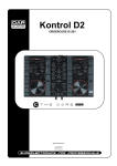
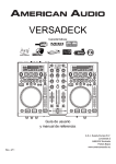
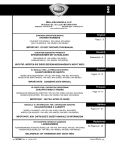
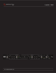
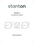
SA-5
The Official Mixer of
The Allies All-star Beatdown
OWNER’S M A N U A L
STANTON MAGNETICS, INC
[email protected]
www.STANTONDJ.com
© 2003, Stanton Magnetics, Inc.
WELCOME!
WA R R A N T Y
Thank you for making Stanton your first choice in professional DJ mixers. This
innovative mixer has been developed with input from the professional DJ
community, bringing to the marketplace a previously unavailable, affordable
combination of user-friendly, functional design, rugged construction, and
professional quality features.
This unit has been designed and manufactured using quality components.
Therefore, it is warranted to be free from defects in materials (limited as specified
below), and workmanship for a period of twelve (12) months from the original
purchase date. During this period, all service and parts necessary to repair a
defect will be free of charge. This limited warranty applies to mechanical parts
which are subject to wear and tear as specified:
Stanton and your authorized Stanton dealer are dedicated to your complete
satisfaction by offering benchmark service and support throughout the long life of
your Stanton product.
• Faders (except P&G faders), specified durability: 15,000 cycles;
• Rotary potentiometer, specified durability: 10,000 cycles;
• Switches, specified durability: 10,000 cycles.
We appreciate your patronage, and look forward to many years of making music
together.
PL E A S E RE A D C A R E F UL LY B E F O R E U SE
FAI LU R E TO F O LLO W TH E I N S TR U C TI O N S PR I N TE D B E LO W M AY V O I D WAR R AN TY
• Follow all security advice printed on your mixer.
Consequently, the parts listed above are warranted to be free from defects in
materials and workmanship for a period of thirty (30) days from the original
purchase date.
The included Penny & Giles faders carry a twelve (12) month warranty. For the
warranty to be valid, please complete the warranty registration card attached or
fill out the online registration at www.STANTONDJ.com
Mail completed warranty cards to:
Stanton Magnetics, Inc, 3000 SW 42nd St., Hollywood, FL. 33312
• When removing the unit's AC plug from the power source, grasp and pull
the plug, NEVER the cord itself!
• Avoid placing your mixer near heat sources, such as power amplifiers.
• When in use, place your mixer on a stable surface, away from vibration.
Always use care when carrying your mixer. Impact, or heavy vibration may
compromise the unit's mechanical integrity. The manufacturer is not
responsible for damage resulting from an impact, or misuse.
• When in use, place your mixer away from sources of hum or noise, such as
transformers, or electric motors.
• To prevent overheating, always provide your mixer with adequate ventilation
air space.
• Avoid stepping on your mixer's AC cord. Repeated compression of the cord
may lead to electrical shorting.
• To avoid damage due to AC voltage peaks, always disconnect your mixer
from the power source during electrical storms. If possible connect mixer
to a surge protector.
• Your mixer contains no user-serviceable parts. The manufacturer is not
responsible for any damage or personal injury resulting from unauthorized
user-servicing or modifications. In addition, the warranty will be void if and
unauthorized service by the user is detected. Always return your mixer to an
authorized Stanton dealer for servicing.
SUPERIOR SOUND TECHNOLOGY
The audio quality of the SA-5 is nothing short of revolutionary for DJ mixers in it’s
price class. The SA-5 was designed by Stanton’s new product development
team, seasoned audio professionals who have designed world class
professional recording studio and broadcast mixers and product managers who
are working DJs and work closely with some of the world’s most respected DJs.
They have taken their knowledge and experience to create the SA-5, a DJ mixer
with superior audio quality and unprecedented value. Come hear the difference!
S A - 5 F E AT U R E S
T E C H N I C A L S P E C I F I C AT I O N S
Line input:
2 (RCA) x 2 channels, -10 dBV / 10 kOhm
Session Input:
2 (RCA), -10 dBV / 10 kOhm
Phono input:
2 (RCA) x 2 channels, -50 dBV / 47 kOhm
Mic input:
1(1/4") -50 dBV / 2.4 kOhm balanced
Master output:
2 (1/4”) Balanced / 2 (RCA) unbalanced,
The SA-5 “The Official Mixer Of The Allies All-Star Beatdown”
Introducing the world’s first all fader battle mixer. Designed by Stanton based on
DJ Infamous’ requirements, the SA-5 is a high-end, affordable mixer with all the
requirements of today’s top turntablist. The simplicity of the layout is sure to make
the SA-5 the preferred mixer for the battle circuit.
+4 dBu balanced / -10 dBV unbalanced
Record output:
2 (RCA), -10 dBV / < 100 Ohms
Headphone output:
2 (1/4 inch), 1 (1/8 inch)
Features include:
• Only mixer in the world with all faders (no rotary knobs)
Greater than 32 Ohm load
Frequency Response (Line):
20 Hz to 20 kHz +/-1 dB
THD+N:
< 0.015 % at 1 kHz
Signal to Noise Ratio
(ref: max level):
> 110 dB (main signal path)
Noise:
< -92 dBV (Line input to any output)
Channel EQ:
Hi
+9, -45 dB, (Kill)
Mid +9, -35 dB, (Kill)
Low +9, -55 dB, (Kill)
Crosstalk:
< -90 dB at 1 kHz
Channel and Crossfader Kill:
< -100 dB
Dimension (LxWxD):
17.5 in x 14.2 in x 4.3 in
Weight:
• OS II optical phono/line switches (for "noise-free" transforms) with lock feature
• 3-way adjustable curve control on line faders & cross fader
• Balanced Master output
• 2 Phono, 2 Line, 1 switchable Mic / Session inputs
• 3 position cue select switch (Pre CF / Post CF / Master). An all new concept in
cueing: Post Fader Cue allows you to listen to your scratches in the headphone
while using the crossfader as normal
• Program reverse
(44.5 cm x 36 cm x 11 cm)
• Master output attenuation control
8.6 lbs (3.9 kg)
• Phono input attenuation control
R E P L A C E M E N T PA RT S
To replace the cross or channel faders, follow steps 1 and 2 of the cleaning
instructions. The following replacement parts are available from Stanton or your
local Stanton dealer.
CF-PG110
Penny & Giles crossfader/ line fader
OS2
Optical Scratch Switch (phono/line selector)
PS-16US
US Power Supply (110v)
PS-16EU
European Power Supply (220v)
PS-16UK
UK only Power Supply (240v)
• 3 headphone outputs (2 x 1/4” and 1 x 1/8” minijack) w/ headphone mute button
• New screwless faceplate
• Includes custom designed P&G (Penny & Giles) crossfader and line faders.
• Unique recessed front panel design prevents DJ’s from accidentally damaging
the headphone jack and the mixer during battling
• An ergonomic layout for non-interrupted performance
DESCRIPTION OF FUNCTIONS
2
3
FADER CLEANING AND REPLACEMENT
5.
4
6.
Examine the center channel of the fader body (found inside the bottom of
the fader casing) and if dirty, clean using cotton buds.
Re-assemble and lubricate the fader as follows:
a) Secure the end block and guide rail onto the fader body.
b) Insert track into the fader body.
1
c) Insert slider assembly onto guide rail and into the fader body. Move
6
slider from end to end to disperse the oil evenly. Carefully wipe away any
excess oil using a tissue or cloth.
5
8
7
10
9
12
d) Lubricate the guide rail by placing one drop of silicon liquid oil onto the
guide rail (F).
e) Insert dust cover.
14
11
7.
13
8.
15
15
16
18
Attach fader to fader plate. (NOTE: As noted earlier if you do not want to
change positioning of fader, keep the 2 fader plate screws loose and shift
the fader until it is aligned with the marks you created in step 1, then
tighten fader plate screws.)
REPLACING THE FADER:
1. Once the fader has been removed, simply plug the connector into the new
fader.
2.
17
1.
Session Level control: Controls the input level of the session or mic input,
depending on setting of session/ Mic switch (27).
2.
Gain: Controls the gain of each input channel. The sensitivity of the gain
faders is adjusted by the phono trim (25) knob on the back of the mixer.
3.
4.
5.
f) Insert fader track back into fader body with wires coming out open
end of fader body.
g) Secure the remaining end block ensuring that the track wires (I) are
not pinched between the end block and fader casing.
Once assembled, move the slider from end to end to ensure operation is
smooth.
Place fader back in mixer and replace 2 outer screws to secure fader.
R O TAT I N G T H E O S 2 S W I T C H E S
The optical scratch switches (OS2) on the Stanton SA-5 mixer can be rotated to
8 different positions. Follow the steps below to rotate the OS2 to the position you
like:
1. Make sure the mixer is powered off. Remove the faceplate of the mixer.
2.
Remove the two outer screws from the OS2 as indicated in diagram. Do
not remove the two inner screws. Removing the two inner screws will
detach the OS2 from its plate.
Program Reverse: Reverses the signal of input channels 1 and 2. When
switched down, channel 1 will control channel 2’s inputs.
3.
Rotate the OS2 to the position you like. Replace the two outer screws to
secure the OS2 in place.
Master Volume control: Controls the overall signal output level of the
mixer. The sensitivity of this fader is controlled by the master trim knob
(21).
REPLACING THE OS2:
Line Fader Reverse: Reverses the direction of each respective line fader.
When switched down, the channel will be at full volume when the fader is
down. The volume will decrease as the fader is moved upward.
1.
Follow steps 1 and 2 above. Remove switch from mixer and detach the
connector from switch.
2.
Attach the connector for OS2 to the replacement switch and replace two
outer screws to secure the OS2 in place.
FADER CLEANING AND REPLACEMENT
After constant scratching, the SA-5 faders may need to be cleaned and
lubricated from time to time. This will ensure long life and keep a smooth feeling
throughout the fader's lifetime. Follow the instructions below to lubricate and
clean your faders:
MIXER FUNCTIONS
6.
Crossfader Reverse: Reverses the direction of the crossfader. When
switched down, channel 1 will be assigned to the right side of the
crossfader, and channel 2 to the left side.
7.
OS2 lock: Locks the OS2 in its current position to avoid accidentally
switching sources. Whether the OS2 is in phono or line, activating the OS2
lock will keep it there even if the OS2 is moved.
8.
Cue Level: Controls the headphone output level.
9.
EQ: Individual controls for low frequency, midrange, and high frequency
equalization with (+9dB/Kill) Note: Any changes made to EQ settings will
change the overall output level.
REMOVING A FADER:
1.
2.
3.
4.
Make sure mixer is powered off and power supply is disconnected from the
back of the mixer.
To remove the lower faceplate, take off all the fader knobs and then remove
the 4 screws located on the sides of the mixer (2 on each side). Lift up on
the faceplate and it will slide off.
Remove the fader to be cleaned or replaced by unscrewing the 2 outer
screws on the fader plate (removing the 2 inner
screws will detach the fader from the fader plate).
Disconnect the fader from the mixer by removing
the connector on the bottom of the fader.
CLEANING A P&G FADER:
1.
2.
3.
Remove 2 mounting screws from fader plate.
Figure 1
(NOTE: The P&G fader is designed with floating
mounting threads for precise mechanical centralizing of the fader. If you
desire to keep your fader`s current mounting position we suggest that you
make 2 marks on both ends of the fader on the fader plate to indicate the
P&G fader position.) See Figure 1.
Once fader is removed from the unit, remove the two screws (A) from the
end of the fader body where the wires exit the fader casing. Pull away the
end block. Withdraw the dust cover (B). Taking great care, remove the
slider assembly (C), ensuring that the wiper contacts (D) are not damaged
as this will affect the operation of the fader. Clean the slider assembly by
gently wiping the wiper contacts and slider bearings (E) using a tissue or
cotton bud. If the slider bearings are excessively worn, as indicated by
excessive slider rocking, then contact Stanton for replacement.
Remove the single upper screw
C
B
on the opposite end block to
remove the guide rail. Clean the
F
guide rail (F) with a tissue or
E
A
cloth, removing all traces of dirt
G
and contamination.
D
4.
Remove the fader track (G) by
slowly withdrawing from the unit.
Place the fader track on a desk or working surface with black contacts
facing upwards. If necessary, the track can be washed in warm water,
wiped gently then dried thoroughly using a dry cloth. Use a lint free cloth or
swab to wipe the tracks and check for marks along the track. (Note: Lint
free cloth should be used to avoid dust and fibers being deposited on the
track). If the track appears excessively worn, or if cleaning does not
improve its operation, replacement may be necessary.
10. Cue Select: On this feature, PRE and POST refer to the crosfader. In
"PRE" position, the signal of control selected by the Cue pan fader will be
monitored (pre-line fader, pre-crossfader) as a stereo signal in the
headphones. The “POST” position, is somewhat similar to the “PRE”
position, except the signal is post crossfader (pre-line fader, postcrossfader), so if the cue pan fader is centered, the signal received in the
headphone depends on the position of the crossfader. In "MASTER"
position, the signal monitored will be pre-master volume (post-faders),
meaning the signal will still be present in the headphone even if the Master
volume control is turned down.
11. Optical Scratch Switches (OS2): Switches between the phono and line
inputs.
12. Cue Pan: Fades the headphone output between channels 1 and 2,
effectively allowing the user to preview a mix. See cue select (10).
13. Power Indicator: The illuminated Allstar Beatdown logo also doubles as
the power indicator.
14. OS2 Lock Indicator: Indicates when the OS2 lock (7) is on .
15. Channel Fader: Controls the output level of each channel.
16. Input Level Meter: Monitors each channel’s input level.
17. Crossfader: Fades the overall mixer output between channels 1 and 2.
18. Headphone Mute: Mutes the headphones without having to move the
headphone volume knob.
BACK P ANEL
B A C K PA N E L
28. Headphone output: Standard 1/4” headphone output connector.
22
23
25
26
25
26
27
20
28
29
19
29. Session/Mic switch: Used to assign the Session/Mic fader to either the
Session input or the MIC input.
30. Microphone input: 1/4” connector for connecting a microphone.
31. Phono Inputs: Phono level inputs for channels 1 and 2. Do not plug line
outputs into phono inputs.
32. Line inputs: Line level inputs for channels 1 and 2.
30
21
24
31
32
31
F R O N T PA N E L
32
19. AC IN: Input connection for the included power supply.
20. Power switch: Turns the mixer on or off.
21. Balanced Master output: TRS balanced (1/4”) connectors are typically
used to connect to a P.A. mixer or an amplifier for live performances or a
recording console for recording.
22. Unbalanced Master output: RCA connectors are typically used to connect
to a home stereo or to another mixer with RCA inputs for practicing or team
routines. Several SA-5’s, can be daisy chained from this output via the
session input (25).
23. Master Trim: Controls the sensitivity of the Master output. Great when an
additional boost or cut is needed.
24. REC: The record output is not affected by the Master volume control.It can
be used to record to a computer, CD, MD, & tape recorder, even while the
master volume is turned down.
25. Phono Trim: Used to adjust the gain of the phono pre-amp. Use this knob
to control the sensitivity of the gain faders.
26. Ground connector: Connects to the turntable ground connector to
eliminate electrical hum. Ground cables usually supplied with turntables.
Some newer turntables such as the Stanton STR8-150 do not require a
ground cable because they are grounded internally.
27. Session Input: This extra line level input is controlled by the session level
fader (1) when the Session/Mic switch (27) is switched to session (the up
position). It can be used as an extra line input or as a session input for
team routines.
33
34
34
34
35
36
35
37
33. Headphone output: Standard 1/8” (mini jack) headphone output
connector.
34. Reverse indicator LED’s: The LED’s indicate the status of the fader
reverse functions. The respective LED lights up when a fader is reversed.
35. Line fader curve switch: Three-position switch selects between a sharp,
mid and long fade for the corresponding line fader.
36. Cross fader curve switch: Three-position switch selects between a sharp,
mid and long fade for the crossfader.
37. Headphone output: Standard 1/4” headphone output connector.