1
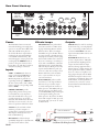
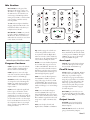
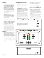
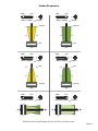
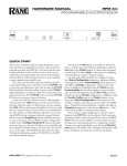
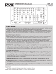
OPERATORS MANUAL
TTM 56S
PERFORMANCE MIXER
Quick Start
Congratulations! You are the proud owner of an exceptional performance instrument. Experienced turntablists will find the TTM
56S comfortable and familiar. The TTM 56S has many unique
features which are mastered quicker if you read the manual. Right!
We know you can’t resist jumping right in, but please read at least
this portion of the manual. It will help you get a good start.
About the faders: The program faders and crossfader are magnetic,
non-contact faders. This means No travel noise – No bleed – Ever!
The electrical performance of the faders is unaffected by use. Old
habits are hard to break, but you really don’t have to mess with
these faders. The magnetic faders in this mixer are very different
from what you are used to. Be sure and read the Q and A section
on page Manual-6.
Special Features:
• KILL switches behave like transform controls, to quickly cut a
signal in or out. Be sure these switches are up to get sound!
• Separate CONTOUR controls for each fader and the crossfader
allow continuous adjustment from smooth blend to fast cut.
• The CHANNEL SWAP switch allows the left-hand or righthand fader to control PGM 1 or PGM 2.
• Auxiliary Inputs and Outputs, with independent level controls,
give session mixing ability.
AUX Inputs may be used for a drum machine, keyboard, etc.
AUX Input comes in after the Crossfader and after the FlexFX loop.
AUX Outputs may be used for recording, booth monitoring, or a second zone.
AUX Output is the same mix as the Master.
• FlexFX™ allow individual assignment of PGM 1, PGM 2 or both to the effects loop. The effects loop is post-fader. You get great results
when using the program faders or crossfader with reverb or other delay effects. For instance, reverb and echo tails are still heard after
the fader is off. The WET/DRY pan lets you control how much of the effect is in the mix.
• Three-band Accelerated-Slope™ EQ allows full cut of each band. The EQ engage switches lets you A/B compare or quickly transform
the EQ effect.
• Two 10-segment meters provide Dual-Mono-Cue or Stereo-Master operation.
• Yes, we included a power switch on the rear.
The flexibility of the TTM 56S can result in some initial confusion. The CHANNEL SWAP switch, KILL switches, REVERSE switches,
Faders and Crossfader are all different ways to cut the signal. We recommend trying one thing at a time. Check that the KILL switches
are ON (up position). Make sure the CHANNEL SWAP switch (and its yellow LED) is off . Start by changing the Contour of each fader,
one at a time. See the diagrams on page Manual-5 to understand the fader responses under different settings, with REVERSE on and off.
Once you understand the controls, start creating!
WEAR PARTS: This product contains no wear parts.
Manual-1
Rear Panel Hook-up
TTM 56S
COMMERCIAL AUDIO
EQUIPMENT 24TJ
MADE IN U.S.A.
RANE CORP.
U.S. PATENT 6,813,361
POWER
R
ACN 001 345 482
MASTER
L
PHONO
GROUNDS
FlexFX
OUTPUTS
AUX
OUT
PGM 2
L
IN
4
L
R
Power
The TTM 56S features an internal
universal switching power supply that
operates on any AC mains 100 to 240
VAC, 50 or 60 Hz (most places in
the world). All that is required when
traveling is the appropriate IEC line
cord available in each country. The
universal supply is a major plus for the
traveling DJ. The POWER switch is
just above the power connector. You
know what to do with this, but leave it
off until everything is connected.
Inputs
PGM 1 and PGM 2 each have two
inputs, each assignable PHONO or
LINE. For a turntable input with
RIAA compensation, push the corresponding switch up to PHONO. For
all other sources such as CD or MP3
players, push the corresponding switch
down to LINE.
PHONO GROUNDS provide
independent ground connect points
for turntables. It is very important
that each turntable have a very good
ground connection to one of these
terminals. The thumbscrews will come
off if they are over-rotated, so be careful not to spin them off and lose them.
AUX IN may be used with a drum
machine, groovebox, sampler, or
another mixer’s output for session mix.
This Input is mixed after the Crossfader and FlexFX loop.
MIC INPUT is a balanced input
specifically designed for a dynamic mic
(a condenser mic will not work).
Manual-2
L
1
L
PHONO
4321
R
OUT
R
IN
UNBALANCED
4
Effects Loops
R
3
O
N
R
2
1
1
2
3
EFFECTS
4
4321
LINE
TIP = SEND
RING = RTN
Outputs
MIC EFFECTS insert jack is unbalanced. It is wired for ¼" TRS, meaning Tip=Send, Ring=Return and the
Shield or Sleeve. This is an independent Effects Loop for the Mic. There is
no engage switch, so the Mic signal is
always processed when you have a plug
inserted and an effects box connected.
If you are connecting to an effects processor with a Send/Return (sometimes
called Insert) jack, a single TRS cable
will work. If your effects processor has
separate Send and Receive jacks, you
need a “Y” cable. You can buy a Send/
Return cable from your local music
store, or you can make one of your
own as shown below.
FlexFX EFFECTS jacks are unbalanced mono ¼" TS (Tip and Sleeve).
This stereo loop is used for output
to (send) and input from (return) an
effects processor. The SEND jacks provide the output to your effects processor. The RETURN jacks provide input
for the signal returning from your
effects processor. If you have an effects
device with a single ¼" TRS, tip=send,
ring=return jack, you need a “Y” cable,
as shown below.
+
AUX OUT may be used for recording,
booth monitoring, a second playback
zone, or connecting another mixer for
session mix. AUX OUT is the same
signal as the Master Mix with its own
Level control.
MASTER OUT includes two sets
of stereo outputs: The ¼" TRS jacks
provide balanced (Tip-Ring-Sleeve)
output. Use this balanced output
whenever driving equipment with a
balanced input, or when running distances greater than 10 feet (3 meters).
Never use a mono ¼" Tip/Sleeve (no
ring) plug in this jack. Use the RCA
unbalanced outputs for shorter runs
connecting to unbalanced devices. See
the RaneNote “Sound System Interconnection” if you need to convert
between balanced and unbalanced or
run long distances.
1-CONDUCTOR SHIELDED CABLE
+
SEND
SHIELD
T = SEND
R = RETURN
S = SHIELD
BALANCED
2
SEND
R
100-240V
50/60 Hz
20 WATTS
PGM 1
3
L
RETURN
MIC
BALANCED
+
1-CONDUCTOR SHIELDED CABLE
SHIELD
+
SHIELD
Send/Return Cable Wiring (Insert Cable)
RETURN
Mic Section
MIC LEVEL sets the gain of the
Mic Input. The range is off to +44
dB. There is no engage switch, so set
the Mic Level to zero (0) when you
aren't using it. The Mic Input minimum gain is 26 dB, so a line-level mic
source (such as a wireless receiver)
must be padded.
PGM 1
4
10
MIC LEVEL
8
0
10
3
8
0
L
+6
PAN
SOURCE
10
GAIN
L
R
PAN
R
OFF
HIGH
10
+6
OFF
OUT
OUT
OFF
FlexFX
+6
PGM 2 inputs are sent to the right
side of the crossfader. (with the Fader 2
Reverse switch out and LED off )
SOURCE switches select which inputs
are assigned to each of the Programs.
PGM 1 can switch between inputs 1
and 2. PGM 2 can switch between
inputs 3 and 4.
GAIN controls adjust the signal level
before it gets to the Faders. Set the
Gain controls to indicate an average
signal level of +4 on the meter with the
program faders set to maximum. Don't
use the Gain controls to set the output
level...use the Main Level control to set
the output level. This is a very simple
thing, yet makes a huge difference in
mixer performance.
10
4
6
0
10
8
8
OFF
AUX IN
MASTER
CUE
+6
LOW
OUT
OUT
DRY
WET
PGM 1
PGM 2
CUE
SLOW
KILL
FAST
SLOW
REVERSE
FAST
CROSSFADE CONTOUR
EQ switches engage the 3-band
tone
MONO PGM1 / PGM2
STEREO HOUSE
controls. EQ switches may be used
in conjunction with the High, Mid
and Low controls as “kill” switches by
turning any or all of them Off. Set the
rotary controls and flip the switch.
OL
+8
+4
+2
0
–2
–4
–8
PGM 1 inputs are sent to the left side
of the crossfader. (with the Fader 1
Reverse switch out and LED off )
0
PGM 2
LOW
FADER 1 CONTOUR
Program Sections
6
PHONES
PGM 1
8
CHANNEL
SWAP
Combined response of the Mic tone controls
4
2
+6
MID
KILL
50k
10
AUX OUT
MIC LOW
0
0
8
EQ
MID
6
6
2
+6
+12
4
4
2
IN
IN
MIC HIGH
OFF
AUDIO PRECISION AMPL(dBr) vs FREQ(Hz)
20
18
16
14
12 Low +12, High +12
10
8
6
4
2 Low 0, High 0
0
-2
-4
-6
-8
Low -12, High -12
-10
10k
4
MAIN
HIGH
-12
OUTPUT
LEVELS
6
2
GAIN
+12
2
1k
4
OL
OFF
-12
2
SOURCE
8
0
2
6
EQ
MIC HIGH and LOW tone controls
provide as much as 12 dB of boost or
12 dB of cut. These controls have no
effect when the controls are set to their
center detent (12 o'clock).
100
1
6
2
The OL indicator lights 6 dB before
clipping. Adjust the Mic Level so the
OL indicator flashes only when you
really shout into the mic.
-12
-14
-16
-18
-20
20
PGM 2
4
HIGH tone controls affect frequencies –16
above 4 kHz. The range of control is –24
+6 dB to Off (full kill). The center detent position leaves this filter inactive.
This filter is just above the vocal range,
A
and can make small tonal changes, or
eliminate high frequency signals.
MID tone controls affect frequencies
from 300 Hz to 4 kHz (vocal midrange). The range of control is +6 dB
to Off (full kill). The center detent position leaves this filter inactive. Use for
small tonal changes or to cut midrange
signals.
LOW tone controls affect frequencies below 300 Hz. The range is +6
dB to Off (full kill). The center detent
position leaves the filter inactive. These
filters influence signals below the vocal
range. Use to adjust or eliminate bass
beats.
PAN controls adjust the Left and
Right balance of PGM 1 and PGM 2.
SLOW
REVERSE
FAST
FADER 2 CONTOUR
REVERSE
KILL switches provide quick program
mute, much like the Transform switches on the previous TTM 56. The signal
is ON in the up postion, the straight
out position Kills the signal.
Aux Input
AUX IN adds another line-level input
to the mix. This input comes in after
the Crossfader and FlexFX Loop.
FlexFX Loop
B
TTM 56S
PERFORMANCE MIXER
FlexFX switches
send PGM 1, PGM 2
or both to the stereo effects loop. The
effects loop is post-fader and postcrossfader. You get great results when
using the program faders or crossfader
with reverb or other delay effects. The
effects loop provides separate stereo
send and return jacks. The green indicator lights when FlexFX is engaged
for either Program.
WET/DRY pan control lets you set
the amount of effect in the mix. DRY
equals no effect, WET gives maximum
effect.
Output Levels
MASTER control sets the level for
both the unbalanced and balanced
Master Outputs.
AUX OUTPUT control sets the level
going to the Auxiliary Outputs.
Manual-3
Faders
The program faders and crossfader
are magnetic, non-contact faders. This
means No travel noise or bleed ! The
electrical performance of the faders
is unaffected by use. The program
faders and crossfader each have their
own Contour and Reverse (hamster)
controls. Magnetic faders are very different from what you are used to. Read
Maintaining Magnetic Faders on
pages Manual 8-9.
CHANNEL SWAP switch allows
the left-hand or right-hand Fader to
alternately control PGM 1 or PGM 2.
(Don't confuse with the REVERSE
switches, see below.)
CONTOUR controls allow smooth,
continuous adjustment of contour. The
range of control is from SLOW blend
to FAST cut, adjustable independently
for each fader and the crossfader. See
the illustrations on the next page.
REVERSE switches change the direction of the faders. When a Reverse
switch is engaged on a PGM fader,
up is down and down is up (hamster).
When the Reverse switch is engaged
on the Crossfader, PGM 1 goes to the
B side and PGM 2 goes to the A side.
Meters
Meters provide switchable true stereo
Master Mix or dual-mono PGM1 /
PGM2 indication of Pre-Program fader signal levels. Ten-segment resolution
is provided with a one second, peak
hold. Use the meter to set the GAIN
controls. With the program fader set to
maximum, the input GAIN should be
set to indicate an average level of about
+4 dB.
Headphone Cueing
• The headphone output of the TTM
56S delivers very high volume.
PHONES Level control sets the output level of the headphone amplifier.
• To avoid pain, never put headphones
on your head before plugging them in.
MASTER / CUE switch is used to
select the headphone monitor source:
• Always start with the PHONES Level
turned down, and then turn it up.
Use MASTER (out) to rehearse your
performance. This signal is the same as
the Master Out, but is not affected by
the Master Level control.
• Because of the high current and low
output impedance, never short one
side to ground, or short left and right
together as is possible with mono cup
headphones.
Use CUE (in) to monitor the Program
Input signal before fadingPGM
in.1This
signal is not affected
by
the
Program
1
2
Faders or Crossfader.
Because
the Effects
SOURCE
GAIN
Loop is after the Fader, you will not
hear
MIC LEVEL OL
effects in the Cue.
4
4
2
6
2
0
4
2
10
L
+6
L
R
HIGH
CUE slider Pans between
PGM 1PANand
PGMMIC
2 HIGH
in the headphones when the
EQ
CUE switch is depressed. When
the
MID control has no
switch is released, this
effect.MIC LOW
-12
+12
4
+6
R
OFF
2
8
OFF
+6
0
10
4
6
0
10
4
6
0
10
8
HIGH
8
AUX OUT
EQ
OFF
OUT
2
+6
MID
8
PHONES
PGM 1
10
6
2
+6
+12
6
4
2
IN
OUT
The headphone ampLOW
in the TTM 56S
has a high
AUX IN power output (unlike most
you have used before). There are notable differences…
0
10
PAN
IN
OFF
-12
8
0
10
OFF
OUTPUT
6
LEVELS
• Low power3 headphone
stages
typically
4
use large resistors
on their outputs,
SOURCE
GAIN
which allow shorting, but
prevent high
MAIN
power. The TTM 56S gives you high
power, but does not allow shorting.
8
0
8
PGM 2
6
PGM 2
FlexFX
OFF
MASTER
CUE
+6
LOW
OUT
OUT
DRY
WET
PGM 1
PGM 2
CUE
KILL
CHANNEL
SWAP
SLOW
KILL
FAST
FADER 1 CONTOUR
SLOW
REVERSE
FAST
CROSSFADE CONTOUR
SLOW
REVERSE
FAST
FADER 2 CONTOUR
REVERSE
MONO PGM1 / PGM2
STEREO HOUSE
OL
+8
+4
+2
0
–2
–4
–8
–16
–24
A
B
TTM 56S
PERFORMANCE MIXER
HEADPHONES
Manual-4
Fader Response
SLOW
FAST
FADER 1 CONTOUR
SLOW
REVERSE
FADER 2 CONTOUR
REVERSE
FULL ON
OFF
OFF
SLOW
REVERSE
FAST
FADER 2 CONTOUR
REVERSE
OFF
OFF
FULL ON
FULL ON
FAST
CROSSFADE CONTOUR
FAST
FULL ON
FAST
FADER 1 CONTOUR
SLOW
SLOW
SLOW
REVERSE
FAST
CROSSFADE CONTOUR
REVERSE
Channel faders and Crossfader illustrating the effects of the Reverse and Contour controls.
Manual-5
Magnetic Fader Q and A
Maintaining Magnetic Faders
Q: Will I damage the faders if I spray them with bad stuff or
spill bad things in them?
A: No. The faders in the TTM 56S are designed with materials
highly resistant to corrosion and most chemicals. There are no
electrical contacts to clean or damage. While bad things may
change the feel of the faders, bad things will not affect the
sound. To clean faders that have had a bad thing put in them,
follow the simple instructions on page Manual-8.
Q: Can I install magnetic faders in any other mixer?
A: Sorry. The connectors may be similar, but the circuits are very
different. Connecting the faders to anything other than the intended cable in the TTM 56S could permanently damage them.
Q: Can I install other faders in my TTM 56S?
A: No. The cable connections are specially designed for Rane magnetic faders.
Q: Can I install a different magnetic fader in my mixer or swap
the position of my faders?
A: No. In order to achieve the highest possible accuracy, each
magnetic fader is factory calibrated for the location in which it
was shipped. For information about replacement or calibration,
contact Rane Customer Service. If you remove the faders for
cleaning, make sure you mark them. This helps you to put them
back in the same location.
Q: Is the same fader used in the TTM 56 as the TTM 56S?
A: Yes. We finally get to say yes.
There are no electrical contacts to clean!
The faders in the TTM 56S are designed with materials highly
resistant to corrosion and most chemicals. While the faders will
handle millions of operations, they may become dirty over time.
Bad things may be spilled or sprayed into the faders. In either case,
the faders are not damaged and the sound quality is unaffected.
Cleaning is only required to maintain the feel of the faders.
The faders are self-lubricating and with normal use, should
not require additional lubrication. If you wish, you can use a light
silicone lubricant rated for use with electrical parts. This will help
maintain the feel. We recommend Caig DeoxIT FaderLube F100
spray lubricant.
Order DeoxIT® F100 from CAIG Laboratories, Inc.
12200 Thatcher Ct.
Poway, CA 92064
Phone 858-486-8388
Fax 858-486-8398
Web www.caig.com
Never use a heavy lubricant or grease. Doing so will not
damage the faders, but can undo the feel. If grease was used, it may
be removed by following the cleaning instructions. Light lubrication is possible with the Lexan plate on. A couple of drops or a
short spray are all that is required. Make sure the products you use
are suitable for use with electrical parts that contain plastic.
Sensors
Manual-6
Magnetic Slider Rail Cleaning
a. Move the carrier all the way to one side.
b. Use a soft lint-free cloth to wipe off rails.
c. Add a drop of silicone lubricant (or quick spray from aerosol) to the center of each rail.
d. Move the carrier back and forth to distribute lubricant.
e. Do not bend torsion spring or touch sensors.
Fader Removal
For more effective cleaning and lubrication, follow the directions outlined below:
1. Required tools: #1 Philips screwdriver and a pair of clean hands.
2. Disconnect the power.
3. Remove the fader caps by pulling them away from the Lexan faceplate.
4. Remove the four 4-40 screws attaching the Lexan faceplate.
5. Remove the Lexan faceplate. See the picture and instructions. The fader rails are now accessible for normal cleaning and lubrication.
6. If more thorough cleaning is required, or the fader needs replacing, remove the fader by removing the two #4 screws securing it.
7. NOTE: Do not disturb the position of the small sensors at each end of the Fader. If you do, make sure the parts are standing straight before
reinstalling.
8. NOTE: In order to achieve the highest possible accuracy, each magnetic fader is factory calibrated for the location in which it was
shipped. If you remove all the faders for cleaning, make sure you mark them. This helps you to put them back in the correct location.
9. Disconnect the ribbon cable, noting the orientation of the red stripe.
10. Sugary liquids spilled into a fader may be removed by thoroughly rinsing the part in hot water. Removal of grease or other stubborn
debris may require alcohol or contact cleaner.
11. Make sure the part is clean and dry before lubricating or reinstalling.
12. To reassemble, reverse the disassembly procedure.
13. Problems? Contact Rane Corporation customer service at 425-355-6000.
Remove #4 screws
on both fader sides
Mark the location
before disconnecting
the ribbon:
PGM1
PGM2
XFADER
Torsion
spring
Remove the ribbon,
noting the polarity of
the red stripe.
Sensors
Manual-7
Manual-8
PGM 4
LEFT
PGM 3
LEFT
PGM 2
LEFT
PGM 1
LEFT
PHONO
LINE
RIAA
3
SOURCE
4
PHONO
LINE
ON
KILL
GAIN
+12
PGM 2R
PGM 1R
PGM 2L
PGM 1L
CH 2 RIGHT
CH 2 BAL
-12
MIX RIGHT
RIAA
PGM 2 MONO
+10
+7
+4
+2
+0
-2
-4
-7
-10
-20
CH 1 RIGHT
CH 1 BAL
MIX LEFT
+10
+7
+4
+2
+0
-2
-4
-7
-10
-20
ON
KILL
GAIN TRIM
-12
+12
PGM 1 MONO
PHONO
LINE
RIAA
1
SOURCE
2
PHONO
LINE
RIAA
OFF
+6
PGM 2 MONO
PGM 1 MONO
MIX RIGHT
VCA
CH 1 LEFT
LOW
EQ
OL
HIGH
LEVEL
LEVEL
RIGHT
LEFT
CH 2 LEFT
-12
+12
+5
CH 1 FLEXFX
MIC EFFECTS
3.5 mm
+5
B
CH 2 FLEXFX
CROSSFADER
A
HEADPHONE
OUTPUTS
1/4”
CH 2 VCA RIGHT
REVERSE
CONTOUR
CH 1 VCA RIGHT
VCA
CONTROLLER
VCA
CUE / MASTER
PGM 2L
CONTOUR
REVERSE
REVERSE
CONTOUR
CHANNEL
SWAP
MIX LEFT
CUE PAN
OFF
+6
LOW MID HIGH
EQ
OL
CH 2 FADER
BOT
TOP
BOT
TOP
CH 1 FADER
LOW MID HIGH
EQ
OL
GAIN
+44 dB
PGM 1L
MIC INPUT
OFF
AUX INPUT
TIP = SEND
RING = RETURN
WET
DRY
AUX INPUT
LEVEL
15 Hz HP
SEND
RETURN
FLEXFX LOOP
AUX
OUTPUT
LEVEL
MAIN
OUTPUT
LEVEL
AUX OUT
UN-BAL
LEFT MASTER OUT
MIX LEFT
TTM 56S Block Diagram
©Rane Corporation 10802 47th Ave. W., Mukilteo WA 98275-5000 USA TEL 425-355-6000 FAX 425-347-7757 WEB www.rane.com
111500