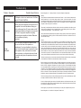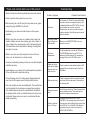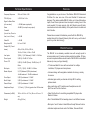
1
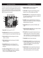
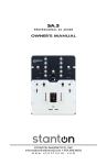
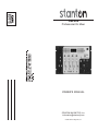
RM.402
Professional DJ Mixer
OWNER’S MANUAL
STANTON MAGNETICS, Inc.
[email protected]
© 2004 Stanton Magnetics, Inc.
Troubleshooting
Problem / Symptom
Sound is distorted
Phono Input
I hear hum.
I hear
feedback
Possible Cause/ Solution
Only plug turntables into this input, do not plug in
CD players or other Line Level sources. Turn down
the INPUT GAIN CONTROL
Make sure you are using good shielded audio
cables. Some less expensive audio cables can be
susceptible to hum and interference. Keep your
audio cables away from AC power cables and AC
transformers. Make sure the mixer is not mounted
too close to high power amplifiers or lighting
equipment power supplies or ballasts. Make sure
your turntables are properly
grounded.
If you are using a microphone, make sure that
you are not too close to the speakers or
headphones. If you hear feedback on the phono
input, then the turntable may be mounted to close
to the speakers. Also, make sure the turntable
base is placed on a surface that does not vibrate
or resonate easily when the speakers are turned
up loudly.
Warranty
Stanton Magnetics, Inc. – Warranty Provision – Returns for Repairs or Replacement
Warranty
Through Stanton’s authorized dealers around the World, Stanton, or one of Stanton’s authorized distributors outside the U.S., will, without charge, repair or replace, at the sole discretion of the entity
responsible for making the repair or providing the replacement, any Stanton merchandise proved defective in material or workmanship for a period of one (1) year following the date of original purchase.
Exceptions to this warranty are as noted below:
The warranty for mechanical parts which are subject to wear and tear are limited to the earlier to occur
of thirty (30) days following the date of original purchase or the following number of cycles: Faders 15,000; Rotary potentiometers - 10,000; and Switches - 10,000.
Stanton will warrant all replacement parts and repairs for ninety (90) days from the date of original shipment. Repairs made necessary by reason of misuse, alteration, normal wear, or accident are not covered under this warranty.
Returns
Authorized Stanton dealers are only authorized to sell and distribute merchandise within a specific
country. All goods requiring warranty repair or replacement must be returned (freight prepaid if not
hand-delivered) to the authorized Stanton dealer from whom the merchandise was purchased and in
the same country where the merchandise was purchased. For purposes of purchases made via the
Internet, the merchandise must be returned to the authorized Stanton dealer in the country where the
authorized Stanton dealer which sold the merchandise to purchaser is located and not the authorized
Stanton dealer in the country where the purchaser is located or the country in which the merchandise
was received. Any returns to a non-authorized dealer or to an authorized Stanton dealer not in the same
country as the merchandise was intended to be sold or as set forth above will void this warranty.
To initiate a warranty repair, you must contact the authorized Stanton dealer from whom you purchased
the merchandise, and follow such authorized Stanton dealer’s return policy.
Stanton assumes no risk and shall be subject to no liability for damages or loss resulting from the specific use or application made of the merchandise. Stanton's liability for any claim, whether based on
breach of contract, negligence, infringement of any rights of any party, or product liability, and relating
to the merchandise shall not exceed the price received by Stanton from your purchase of such merchandise. In no event will Stanton be liable for any special, incidental or consequential damages (including loss of use, loss of profit and claims of third parties) however caused, whether by the negligence of
Stanton or otherwise. To the extent permitted by law and except as otherwise provided above, Stanton
disclaims any express or implied warranties of merchantability or fitness for a particular purpose.
The above warranty provides you with specific legal rights. You may also have additional rights, which
are subject to variation from state to state and country to country.
If there is a dispute regarding the warranty of merchandise that does not fall under the warranty conditions stated above, please include a written explanation with the merchandise when returned pursuant
to the terms and conditions set forth herein.
Please register your product online at www.stantondj.com or mail your completed warranty card to:
Stanton Magnetics, Inc, 3000 SW 42 St. Hollywood, Florida 33312.
Troubleshooting
Please read carefully before use of this product
failure to follow the instructions printed below may void warranty
Problem / Symptom
Possible Cause/ Solution
• Follow all security advice printed on your mixer
• When removing the unit's AC plug from the power source, grasp
and pull the plug, NEVER the cord itself!
No Sound
• Avoid placing your mixer near heat sources, such as power
amplifiers.
• When in use, place your mixer on a stable surface, away from
vibration. Always use care when carrying your mixer. Impact, or
heavy vibration may compromise the unit's mechanical integrity.
The manufacturer is not responsible for damage resulting from
an impact, or misuse.
• When in use, place your mixer away from sources of hum or
noise, such as transformers, or electric motors.
• To prevent overheating, always provide your mixer with adequate
ventilation air space.
• Avoid stepping on your mixer's AC cord. Repeated compression
of the cord may lead to electrical shorting.
• To avoid damage due to AC voltage peaks, always disconnect
your mixer from the power source during electrical storms.
• Your mixer contains no user-serviceable parts. The manufacturer
is not responsible for any damage or personal injury resulting
from unauthorized user-servicing or modifications. In addition,
the warranty will be void if any unauthorized service by the user
is detected. Always return you mixer to an authorized Stanton
dealer for servicing.
No Sound- Master
Output (Booth and
Zone are OK)
Is the power on? Check the power switch.Make
sure the channels are assigned properly to the
crossfaders. Make sure INPUT GAIN, is turned
up and output level control is turned up.
Depending on the input, check the rear panel
selector switches. Check the top panel channel
selector switches.
Make sure that MASTER TRIM on the rear
panel is turned up.
No Sound
Headphones
Do the headphones work with the CUE pan in
the PROGRAM position but not PFL? If so,
make sure that the channel PFL switches are
engaged. Check the CUE LEVEL control.
Signal level is low
even with the faders
and input level controls turned up.
Check to make sure the talkback switch is NOT
engaged on the microphone input. Check the
EQ sliders.
Mixer sounds noisy
Check to make sure that the microphone levels
are turned all of the way down if a microphone
is not being used.
Microphone doesn’t
work
Is the Mic gain turned up? Does the microphone
require phantom power? This mixer does not
provide microphone phantom power.
Sound is distortedLine or CD input
In general, turn down the INPUT GAIN
CONTROL. The input signal may be too loud for
the input gain control setting that you were using.
Is the EQ on? Turn off the EQ. If the distortion
goes away, then you need to turn down the
INPUT GAIN CONTROL.
Technical Specifications
Welcome
Frequency Response
20 Hz to 20 kHz +1 dB
THD+N (Line)
> 0.005 % at 1 kHz
Congratulations on your choice of the Stanton RM.402 Professional
DJ Mixer. You now own one of the most flexible DJ mixers ever
designed. The rackmountable RM.402 offers up to three Microphone
inputs, three Phono inputs and nine Line inputs—making it one of the
most powerful DJ mixers around. And with Stanton’s smooth fader
movement and rock-solid reliability, it’s the perfect mixer for mobile and
club DJs alike.
Signal to Noise Ratio
(ref: max level)
> 109 dB (main signal path)
Noise
-98 dBV (Line input to any output)
Crosstalk
(Line to Line, Phono to
Line, Line to Phono)
> -90 dB
Fader Kill
> -90 dB
Microphone EQ
Hi, Low +12 dB
Graphic EQ (7 band
stereo)
40 Hz, 80 Hz, 160 Hz, 500 Hz,
1.6 kHz, 3.2 kHz, 6.4 kHz + 10 dB
Line Inputs
7(RCA) , 1(1/4” Balanced) -10 dBV / >10 kOhm
Phono Inputs
2 (RCA), -50 dBV / 47 kOhm
Phono / CD
2 (RCA), -50 dBV (Phono) -10 dBV (Line) / 47
kOhm
Mic Inputs
2 (1/4”), 1 (XLR) -50 dBV / 2.4 kOhm
Master Outputs
2 (1/4”) Balanced/ (RCA) unbalanced,
+4 dBu balanced / -10 dBV unbalanced
Please take a moment to familiarize yourself with the RM.402 by
reading through this Owner’s Manual. (And don’t worry—we’ll make it
quick so you can start mixing!)
RM.402 Features
The RM.402 is an extremely versatile mixer with enough inputs to
accommodate many DJ setups including multiple turntables, CD players and microphones. Below we list some of the RM.402’s most salient
features (in case you forgot already!):
• 19” rackmountable DJ mixer with connections for multiple
turntables, CD players and microphones
• 4-channel design with assignable crossfader for mixing a variety
of sources
Zone Output
2 (RCA) unbalanced / -10 dBV
Booth Output
2 (RCA) unbalanced / -10 dBV
Record Output
2 (RCA) unbalanced / -10 dBV
Headphone Output
1 (1/4 inch), 1 (1/8 inch) greater than 32 Ohm load
• Easy monitoring via PFL switches and headphone mix with
Split Cue and Cue Pan functions.
Dimensions (LxWxD)
18.9 in. x 8.66 in. x 4.72 in. (48 cm. x 22 cm. x 12
cm.)
• Fader Start buttons for controlling compatible CD players like
Stanton S-Series
4.5 kg (9.9 lbs)
• Dual 7-band Master EQ for tweaking mixes to suit different venues
Weight
• Individual gain control per channel with clip LED for setting
optimum levels
• Mic inputs 1 and 2 feature 2-band EQ and handy Talkover function
• Individual outputs and level control for Master, Zone and Booth
Making Connections
Application Example
Are you ready to get on the 1’s and 2’s? Let’s make sure you’ve made
all the right connections…
This is a typical setup you’ll find in many nightclubs: 2 turntables, 2 CD
players, plus a microphone for the DJ. Here’s how you would set up
your equipment with the RM.402:
1. Be sure all equipment is powered “OFF” and all of the
RM.402’s Channel faders and Level knobs are at minimum
volume.
Mic 2
Here you can connect a microphone using a 1/4-inch cable. If you
have an XLR-type cable, use the Mic 1 input located on the front
panel.
Channel
This channel offers two Line inputs for connecting CD/MD players, or
the audio output of a DVD player or VCR. A Phono input is also
provided for connecting a turntable.
Channel 2/3
For each channel, you can connect either two Line inputs or one Line
input and a turntable, depending on the position of the
push-switch. These channels also feature a Fader Start function.
Connect the Fader Start cable (provided with any Fader Start
equipped CD player) to the remote input on your CD player.
Channel 4
This channel provides connections for three Line inputs or two Line
inputs and a microphone, depending on the position of the
push-switch.
2. Connect the turntables to the Phono inputs of Channels 1
and 2. Be sure the rear-panel toggle switch for Channel 2 is set to
“PH2” or you won’t hear anything. To avoid hum, don’t forget to
connect the ground wires to the grounding terminals.
3. Connect the CD players to the Line 4 and 5 inputs of Channels 3
and 4.
4. Depending on the type of cable you have, connect your
microphone to the Mic 1 or Mic 2 input.
5. Connect the Master Output jacks to the club’s power amp, EQ or
crossover. Then connect your monitor amp to the Booth output. If
you have a separate amp for a particular area of the club, connect
this amp to the Zone outputs.
6. Set the Input Selectors on the front panel to the appropriate inputs
for each channel.
7. Power everything up and carefully adjust the input levels using the
Input Gain knobs and Mic Level knob.
8. If you want to use the crossfader, set Channels 1 and 3 to “A” and
Channels 2 and 4 to “B”. Otherwise, set them all to “Bypass”.
9. If your CD players support Fader Start, connect the mini-cables
and set the Fader Start switches to “ON”.
10. Slowly raise the Channel faders, Master fader, Booth level, Zone
level and Mic level as appropriate and start mixing!
Description of Functions
16. Input Selector switches: Use these to choose between the
Phono, Line and Mic inputs.
Making Connections
Outputs
17. Talkover switch: Switch this to the “ON” position to enable
Microphones 1 and 2. When moved to the “Talkover” position,
the music is lowered by a preset amount when the mic is in use.
Use the REC output to connect a stand-alone CD recorder, DAT
recorder, or tape deck. Use the BOOTH output to connect directly to
powered monitors or your monitor amp. The ZONE output can be used
if you need separate level control for a particular area of your club,
such as lounge vs. dance floor.
18. Mic Level knobs: Use these to adjust the levels for Microphones
1 and 2. Note that the Talkover switch must be set to “ON” to
hear the microphones.
Master
19. Microphone EQ knobs: Adjust the Hi and Low frequencies of Mic
1 and 2 by +/- 12dB.
These outputs are for connecting your main power amp, EQ,
crossover, etc. Both RCA and 1/4-inch jacks are provided. Using the
Master Output Trim control, you can adjust the overall level being sent
from the outputs—great when an additional boost or cut is needed.
20. Mic 1 input: Connect a microphone here using an XLR cable.
Power Adapter Inlet
21. EQ On switch: Enables or disables the dual 7-band equalizer.
22. Equalizer: A dual 7-band EQ for the Master output. Use this to
“tune” your mix to different venues, or to adjust the overall
tonality of your mixes.
23. Output Level meter: Displays the overall signal level of the
Master output. Can also display levels for the Zone output when
the Zone Meter switch (2) is enabled.
SUPERIOR SOUND TECHNOLOGY
The audio quality of the RM.402 is nothing short of revolutionary for DJ
mixers in its price class. The RM.402 was designed by Stanton’s new
product development team, seasoned audio professionals who have
designed world class professional recording studio and broadcast mixers and product managers who are working DJs and work closely with
some of the world’s most respected DJs. They have taken their knowledge and experience to create the RM.402, a DJ mixer with superior
audio quality and unprecedented value. Come hear the difference!
Connect the RM.402’s power supply here. Screw to the right, unscrew
to the left. You knew that, didn’t you?
Ground Terminals
Connect the grounding cables from your turntables here to avoid hum.
Description of Functions
Description of Functions
At this point, you’re pretty much ready to start mixing. So if you’re a
know-it-all, or you’re just one of those people who like to learn by trialand-error, you are free to throw down. But if you wanna go for the gold
and get your pilot’s license, take a moment and learn what each of the
RM.402’s front-panel controls are about.
15
16 22
23
22
11
2
21
1
6. Headphone outputs: Connect up to two pairs of stereo
headphones using 1/4-inch and 1/8-inch jacks.
7. Cue Pan slider: This adjusts the relative headphone balance
between the Cue mix (PFL) and Master output (PGM).
8. Fader Start switch: Lets you automatically start a CD player from
the cue point by moving the crossfader (requires a compatible CD
player like the Stanton S-Series).
20
4
19
3a
5
3b
18 17 13 8 14 9 12 8 14 10 7
9. Crossfader: Creates a gradual fade between two channels, as
determined by the Crossfader Source selectors (14). Essential for
scratching and smooth house mixing.
10. Master fader: Adjusts the overall level of the Master output
signal.
6
1. Power switch: Turns the power “On” or “Off”.
2. Zone Meter switch: Press this when you want the Output Level
meter (23) to display the Zone output instead of the Master output.
3a. Zone Level knob: Adjusts the level being sent to the Zone
outputs (i.e. monitors).
3b. Booth Level knob: Adjusts the level being sent to the Booth
outputs (i.e. monitors).
4. Cue Level knob: Adjusts the cue level being sent to the
Headphone outputs. Keep this at a reasonable level to avoid
hearing loss.
5. Cue Stereo/ Split toggle switch: Select whether you prefer to
hear the Cue mix and Master output in stereo, or split with the
Cue mix on one side and the Master on the other.
11. Master Stereo/Mono toggle switch: Selects whether the Master
output will be stereo or summed to mono.
12. PFL switch: Push this to assign the channel to the Cue mix in
headphones. (Pop quiz: Do you know what “PFL” stands for?
Answer: “Pre-Fader Level.” In other words, the Channel fader
does not affect the level you hear in the headphone cue mix.)
13. Channel fader: Controls the input channel level.
14. Crossfader Source selectors: These select whether the input
channel is assigned to the left side (A) or right side (B) of the
crossfader. Select “BYPASS” if you don’t want the channel
assigned to the crossfader at all.
15. Input Gain knobs: Use these to adjust the level of inputs. For
optimum signal-to-noise, raise the knob until the “max” LED
lights occasionally (usually around the 2 o’clock position).