1
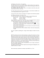
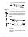
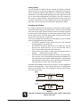
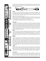
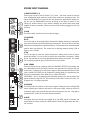
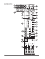
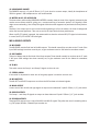
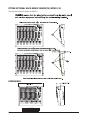
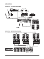
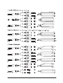
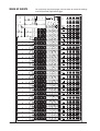
USER GUIDE
1
IMPORTANT
Please read this manual carefully before using
your mixer for the first time.
© Harman International Industries Ltd. 2006
All rights reserved
Parts of the design of this product may be protected by worldwide patents.
Part No. ZM0342-01
Soundcraft is a trading division of Harman International Industries Ltd. Information in this manual is subject to change without notice and does not represent a commitment on the part of the vendor. Soundcraft shall not be liable for
any loss or damage whatsoever arising from the use of information or any error
contained in this manual.
No part of this manual may be reproduced, stored in a retrieval system, or
transmitted, in any form or by any means, electronic, electrical, mechanical,
optical, chemical, including photocopying and recording, for any purpose without the express written permission of Soundcraft.
Harman International Industries Limited
Cranborne House
Cranborne Road
POTTERS BAR
Hertfordshire
EN6 3JN
UK
Tel:
+44 (0)1707 665000
Fax: +44 (0)1707 660742
http://www.soundcraft.com
2
Contents
IMPORTANT SAFETY INSTRUCTIONS
SAFETY SYMBOL GUIDE
INTRODUCTION
WIRING UP
BLOCK DIAGRAM
MONO INPUT CHANNEL
STEREO INPUT CHANNELS
MASTER SECTION
USING YOUR MPM CONSOLE
FITTING OPTIONAL RACK-MOUNT BRACKETS (MPM12/2)
DIMENSIONS
APPLICATIONS
TYPICAL CONNECTING LEADS
MARK-UP SHEETS
TYPICAL SPECIFICATIONS
WARRANTY
4
6
7
8
12
13
16
18
22
24
24
25
28
30
31
32
3
IMPORTANT SAFETY INSTRUCTIONS
Read these instructions.
Keep these instructions.
Heed all warnings.
Follow all instructions.
Do not use this apparatus near water.
Clean only with a dry cloth.
Do not block any ventilation openings. Install in accordance with the manufacturer’s
instructions.
Do not install near any heat sources such as radiators, heat registers, stoves, or other
apparatus (including amplifiers) that produce heat.
Do not defeat the safety purpose of a polarised or grounding type plug. A polarised
plug has two blades with one wider than the other. A grounding type plug has two
blades and a third grounding prong. The wide blade or the third prong are provided for
your safety. If the provided plug does not fit into your outlet, consult an electrician for
replacement of the obsolete outlet
Protect the power cord from being walked on or pinched particularly at plugs, convenience receptacles and the point where they exit from the apparatus.
Only use attachments/accessories specified by the manufacturer.
Use only with the cart, stand, tripod, bracket or table specified by the manufacturer, or
sold with the apparatus. When a cart is used, use caution when moving the cart/
apparatus combination to avoid injury from tip-over.
Unplug this apparatus during lightning storms or when unused for long periods of
time.
Refer all servicing to qualified service personnel. Servicing is required when the apparatus has been damaged in any way, such as power-supply cord or plug is damaged, liquid has been spilled or objects fallen into the apparatus, the apparatus has
been exposed to rain or moisture, does not operate normally, or has been dropped.
Note: It is recommended that all maintenance and service on the product should be
carried out by Soundcraft or its authorised agents. Soundcraft cannot accept any
liability whatsoever for any loss or damage caused by service, maintenance or repair
by unauthorised personnel.
WARNING: To reduce the risk of fire or electric shock, do not expose this apparatus to
rain or moisture.
Do not expose the apparatus to dripping or splashing and do not place objects filled
4
with liquids, such as vases, on the apparatus.
No naked flame sources, such as lighted candles, should be placed on the apparatus.
Ventilation should not be impeded by covering the ventilation openings with items such
as newspapers, table cloths, curtains etc.
THIS APPARATUS MUST BE EARTHED. Under no circumstances should the safety earth
be disconnected from the mains lead.
The mains supply disconnect device is the mains plug. It must remain accessible so as
to be readily operable when the apparatus is in use.
If any part of the mains cord set is damaged, the complete cord set should be replaced.
The following information is for reference only.
The wires in the mains lead are coloured in accordance with the following code:
Earth (Ground): Green and Yellow (US - Green/Yellow)
Neutral:
Blue (US - White)
Live (Hot):
Brown (US - Black)
As the colours of the wires in the mains lead may not correspond with the coloured
markings identifying the terminals in your plug, proceed as follows:
The wire which is coloured Green and Yellow must be connected to the terminal in
the plug which is marked with the letter E or by the earth symbol.
The wire which is coloured Blue must be connected to the terminal in the plug
which is marked with the letter N
The wire which is coloured Brown must be connected to the terminal in the plug
which is marked with the letter L
Ensure that these colour codes are followed carefully in the event of the plug being
changed
This unit is capable of operating over a range of mains voltages as marked on the rear
panel.
NOTE: This equipment has been tested and found to comply with the limits for a Class A
digital device, pursuant to Part 15 of the FCC Rules. These limits are designed to provide
reasonable protection against harmful interference when the equipment is operated in a
commercial environment. This equipment generates, uses and can radiate radio frequency
energy and, if not installed and used in accordance with the instruction manual, may
cause harmful interference to radio communications. Operation of this equipment in a
residential area is likely to cause harmful interference in which case the user will be
required to correct the interference at his own expense.
This Class A digital apparatus meets the requirements of the Canadian InterferenceCausing Equipment Regulations.
Cet appareil numérique de la Classe A respecte toutes les exigences du Règlement sur le
matériel brouilleur du Canada.
Peak inrush current, measured in accordance with EN55103-1, is 7.0A.
5
For your own safety and to avoid invalidation of the warranty please read this
section carefully.
SAFETY SYMBOL GUIDE
For your own safety and to avoid invalidation of the warranty all text marked
with these symbols should be read carefully.
WARNINGS
The lightning flash with arrowhead symbol, is intended to
alert the user to the presence of un-insulated “dangerous
voltage” within the product’s enclosure that may be of sufficient magnitude to constitute a risk of electric shock to
persons.
CAUTIONS
The exclamation point within an equilateral triangle is
intended to alert the user to the presence of important
operating and maintenance (servicing) instructions in the
literature accompanying the appliance.
NOTES
Contain important information and useful tips on the operation of your equipment.
HEADPHONES SAFETY WARNING
Contain important information and useful tips on headphone
outputs and monitoring levels.
Recommended Headphone Impedance >= 200 Ohms.
6
INTRODUCTION
Thank you for purchasing a Soundcraft MPM mixer. The MPM range is our most costeffective mixing solution, bringing you all the features and performance that you
expect from a Soundcraft product, at an extraordinarily low price.
The packaging, which your MPM arrived in, forms part of the product and must be
retained for future use.
Owning a Soundcraft console brings you the expertise and support of one of the
industry’s leading manufacturers, and the results of nearly 3 decades of supporting
some of the biggest names in the business. Our knowledge has been attained
through working in close contact with leading professionals and institutes to bring
you products designed to get the best possible results from your mixing.
Built to the highest standards using quality components and surface mount technology, the MPM is designed to be as easy to use as possible. We have spent years
researching the most efficient methods of control for two key reasons:
1) Engineers, musicians, writers and programmers all need to have very few interruptions to the creative process; our products have been designed to be almost
transparent, allowing this process to breathe.
2) Whether performing or recording, time is a very expensive and rare commodity.
Our products have a user interface which is recognised by millions to be the industry standard because of its efficiency.
The sonic qualities of our products are exemplary - some of the same circuits which
are used on our most expensive consoles are employed in the MPM, bringing you
the great Soundcraft quality in a small format console without compromise.
You will also be glad to know you have a one year warranty with your product from
the date of purchase. The MPM has been designed using the latest high-end software based engineering packages. Every console from Soundcraft has been proven
to stand up to all the stress and rigours of modern day mixing environments.
The entire MPM is manufactured using some of the most advanced techniques in
the world, from high density surface mount PCB technology, to computer aided test
equipment able to measure signals well outside the range of normal hearing. As
each console passes through to be quality checked before packing, there is also a
human listening station. Something we have learnt over the years is that the human
touch counts - and only by using people can you ensure the product meets the high
demands of the user.
ADVICE FOR THOSE WHO PUSH THE BOUNDARIES
Although your new console will not output any sound until you feed it signals, it has
the capability to produce sounds which when monitored through an amplifier or
headphones can damage hearing over time.
Please take care when working with your audio - if you are manipulating controls
which you don’t understand (which we all do when we are learning), make sure your
monitors are turned down. Remember that your ears are the most important tool of
your trade, look after them, and they will look after you.
Most importantly - don’t be afraid to experiment to find out how each parameter
affects the sound - this will extend your creativity and help you to get the best from
your mixer and the most respect from your artists and audience.
7
WIRING UP
Mic Input
The MIC input accepts XLR-type connectors and is designed to suit a wide
range of BALANCED or UNBALANCED low-level signals, whether from delicate vocals requiring the best low-noise performance, or drum kits needing
maximum headroom. Professional dynamic, condenser or ribbon mics are
best because these will be LOW IMPEDANCE. While you can use low-cost
HIGH IMPEDANCE mics, you do not get the same degree of immunity to
interference on the microphone cable and as a result the level of background noise may be higher. If you turn the PHANTOM POWER on, the socket
provides a suitable powering voltage for professional condenser mics.
DO NOT use UNBALANCED sources with the phantom power
switched on. The voltage on pins 2 & 3 of the XLR connector may
cause serious damage. BALANCED dynamic mics may normally be
used with phantom power switched on (contact your microphone
manufacturer for guidance)
The input level is set using the input GAIN knob.
The LINE input offers the same gain range as the MIC input, but at a higher
input impedance, and is 20dB less sensitive. This is suitable for most line
level sources.
WARNING !
Start with the input GAIN knob turned fully anticlockwise when
plugging high level sources into the LINE input to avoid
overloading the input channel or giving you a very load surprise!
Line Input
Accepts 3-pole 6.35mm (1/4") jacks, or 2-pole mono jacks which will automatically ground the ‘cold’ input. Use this input for sources other than mics,
such as keyboards, drum machines, synths, tape machines or DI boxes. The
input is BALANCED for low noise and immunity from interference, but you
can use UNBALANCED sources by wiring up the jacks as shown, although
you should then keep cable lengths as short as possible to minimise interference pick-up on the cable. Note that the ring must be grounded if the
source is unbalanced. Set the input level using the GAIN knob, starting with
the knob turned fully anticlockwise. Unplug any MIC connection when using
the LINE input.
Insert Point
The unbalanced, pre-EQ insert point is a break in the channel signal path,
allowing limiters, compressors, special EQ or other signal processing units
to be added in the signal path. The Insert is a 3-pole 6.35mm (1/4") jack
socket which is normally bypassed. When a jack is inserted, the signal path
is broken, just before the EQ section.
The signal from the channel appears on the TIP of the plug and is returned
on the RING, with the sleeve as a common ground.
The Send may be tapped off as an alternative pre-fade, pre-EQ direct output
if required, using a lead with tip and ring shorted together so that the signal
path is not interrupted.
8
A ‘Y’ lead may be required to connect to equipment with separate send and
return jacks as shown below:
Stereo Inputs STEREO 1/2
These accept 3-pole 6.35mm (1/4") jacks, or 2-pole mono jacks which will
automatically ground the ‘cold’ input. Use these inputs for sources such as
keyboards, drum machines, synths, tape machines or as returns from processing
units. The input is BALANCED for low noise and immunity from interference,
but you can use UNBALANCED sources by wiring up the jacks as shown, although you should then keep cable lengths as short as possible to minimise
interference pick-up on the cable. Note that the ring must be grounded if the
source is unbalanced.
Mono sources can be fed to both paths by plugging into the Left jack only.
Mix Outputs
The MIX outputs are on XLR’s, wired as shown, and incorporate impedance
balancing, allowing long cable runs to balanced amplifiers and other equipment.
Aux Outputs
The Aux outputs are on 3-pole 6.35mm (1/4") jack sockets, wired as shown
on the left, and are balanced, allowing long cable runs to balanced amplifiers
and other equipment.
Headphones
The PHONES output is a 3-pole 6.35mm (1/4") jack, wired as a stereo output
as shown, ideally for headphones of 200Ω or greater. 8Ω headphones are
not recommended.
9
Polarity (Phase)
You will probably be familiar with the concept of polarity in electrical
signals and this is of particular importance to balanced audio signals.
Just as a balanced signal is highly effective at cancelling out unwanted
interference, so two microphones picking up the same signal can cancel
out, or cause serious degradation of the signal if one of the cables has
the +ve and -ve wires reversed. This phase reversal can be a real problem when microphones are close together and you should therefore always take care to connect pins correctly when wiring audio cables.
Grounding and Shielding
For optimum performance use balanced connections where possible
and ensure that all signals are referenced to a solid, noise-free earthing
point and that all signal cables have their screens connected to ground.
In some unusual circumstances, to avoid earth or ground ‘loops’ ensure
that all cable screens and other signal earths are connected to ground
only at their source and not at both ends.
If the use of unbalanced connections is unavoidable, you can minimise
noise by following these wiring guidelines:
•
On INPUTS, unbalance at the source and use a twin screened
cable as though it were balanced.
•
On OUTPUTS, connect the signal to the +ve output pin, and the
ground of the output device to -ve. If a twin screened cable is
used, connect the screen only at the mixer end.
•
Avoid running audio cables or placing audio equipment close to
thyristor
dimmer units or power cables.
•
Noise immunity is improved significantly by the use of low impedance sources, such as good quality professional microphones or
the outputs from most modern audio equipment. Avoid cheaper
high impedance microphones, which may suffer from interference
over long cable runs, even with well-made cables.
Grounding and shielding is still seen as a black art, and the suggestions
above are only guidelines. If your system still hums, an earth/ground
loop is the most likely cause. Two examples of how an earth loop can
occur are shown below.
Warning!
Under NO circumstances must the AC power mains earth be disconnected
from the mains lead.
10
PROBLEM SOLVING
Basic problem solving is within the scope of any user if a few basic rules are followed.
•
Get to know the Block Diagram of your console (see page 12).
•
Get to know what all controls and/or connections in the system are supposed
to do.
•
Learn where to look for common trouble spots.
The Block Diagram is a representative sketch of all the components of the console,
showing how they connect together and how the signal flows through the system.
Once you have become familiar with the various component blocks you will find the
Block Diagram is quite easy to follow and you will have gained a valuable understanding of the internal structure of the console.
Each component has a specific function and only by getting to know what each part
is supposed to do will you be able to tell if there is a genuine fault! Many “faults” are
the result of incorrect connection or control settings which may have been overlooked.
Basic Troubleshooting is a process of applying logical thought to the signal path
through the console and tracking down the problem by elimination.
•
Swap input connections to check that the source is really present. Check both
Mic and Line inputs.
•
Eliminate sections of the channel by using the insert point to re-route the signal to other inputs that are known to be working.
•
Route channels to different outputs or to auxiliary sends to identify problems
on the Master section.
•
Compare a suspect channel with an adjacent channel which has been set up
identically. Use PFL to monitor the signal in each section.
•
Insert-point contact problems may be checked by using an insert bypass jack
with tip and ring shorted together as shown below. If the signal appears when
the jack is inserted it shows that there is a problem with the normalling contacts on the jack socket, caused by wear or damage, or often just dirt or dust.
Keep a few in your gig tool box.
If in doubt please contact Soundcraft customer support.
PRODUCTS UNDER WARRANTY
UK customers should contact their local dealer.
Customers outside the UK are requested to contact their territorial distributor who is
able to offer support in the local time zone and language. Please see the distributor
listings on our website (www.soundcraft.com) to locate your local distributor.
OUT-OF-WARRANTY PRODUCTS
For out-of-warranty consoles purchased in the United Kingdom, please contact the
Customer Services Department (e-mail: [email protected]) at the factory in Potters Bar, Hertfordshire: Telephone +44 (0)1707 665000.
For all other out-of-warranty consoles, please contact the appropriate territorial distributor.
When mailing or faxing please remember to give as much information as possible.
This should include your name, address and a daytime telephone number. Should
you experience any difficulty please contact Customer Services Department (e-mail:
[email protected])
11
BLOCK DIAGRAM
12
MONO INPUT CHANNEL
1 Mic Input
The MIC input accepts XLR-type connectors and is designed to suit a wide range of
BALANCED or UNBALANCED signals. Professional dynamic, condenser or ribbon
mics are best because these will be LOW IMPEDANCE. You can use low-cost HIGH
IMPEDANCE mics, but the level of background noise will be higher. If you turn the
PHANTOM POWER on (top right-hand side of the mixer) the socket provides a suitable powering voltage for professional condenser mics.
ONLY connect condenser microphones with the +48V powering OFF, and
ONLY turn the +48V powering on or off with all output faders DOWN, to
prevent damage to the mixer or external devices.
TAKE CARE when using unbalanced sources, which may be damaged by the phantom power voltage on pins 2 & 3 of the XLR connector.
Unplug any mics if you want to use the LINE Input. The input level is set using the
GAIN knob.
2 Line Input
Accepts 3-pole 6.35mm (1/4") jacks. Use this input for sources other than mics,
such as keyboards, drum machines, synths, tape machines or DI’d guitars. The
input is BALANCED for low noise and top quality from professional equipment, but
you can use UNBALANCED sources by wiring up the jacks as shown in the ‘wiring up’
section, although you should then keep cable lengths as short as possible. Unplug
anything in the MIC input if you want to use this socket. Set the input level using the
GAIN knob.
3 High-pass Filter
Pressing this switch activates the high-pass filter. This reduces the level of bass
frequencies only. Use this in live PA situations to reduce stage rumble or ‘popping’
from mics.
4 Insert Point
The unbalanced, pre-EQ insert point is a break in the channel signal path, allowing
limiters, compressors, special EQ or other signal processing units to be added in the
signal path. The Insert is a 3-pole 6.35mm (1/4") jack socket which is normally
bypassed. When a jack is inserted, the signal path is broken, just before the EQ
section.
13
The Send may also be tapped off as an alternative pre-fade, pre-EQ direct output if
required, using a lead with tip and ring shorted together so that the signal path is
not interrupted (see below).
5 Gain
This knob sets how much of the source signal is sent to the rest of the mixer. Too
high, and the signal will distort as it overloads the channel. Too low, and the level of
any background hiss will be more noticeable and you may not be able to get enough
signal level to the output of the mixer.
Note that some sound equipment, particularly that intended for domestic use,
operates at a lower level (-10dBV) than professional equipment and will therefore
need a higher gain setting to give the same output level.
See “Initial Setup” on page xx to learn how to set GAIN correctly.
6 Equaliser
The Equaliser (EQ) allows fine manipulation of the sound, particularly to improve
the sound in live PA applications where the original signal is often far from ideal
and where slight boosting or cutting of particular voice frequencies can really make
a difference to clarity. There are three sections giving the sort of control usually only
found on much larger mixers. The EQ knobs can have a dramatic effect, so use
them sparingly and listen carefully as you change any settings so that you get to
know how they affect the sound.
HF EQ
Turn to the right to boost high (treble) frequencies above 12kHz by up to 15dB,
adding crispness to cymbals, vocals and electronic instruments. Turn to the left to
cut by up to 15dB, reducing hiss or excessive sibilance which can occur with certain types of microphone. Set the knob in the centre-detented position when not
required.
MID EQ
There are two knobs which work together to form a SWEPT MID EQ. The lower knob
provides 15dB of boost and cut, just like the HF EQ knob, but the frequency at
which this occurs can be set by the upper knob over a range of 150Hz to 3.5kHz.
This allows some truly creative improvement of the signal in live situations, because this mid band covers the range of most vocals. Listen carefully as you use
these controls together to find how particular characteristics of a vocal signal can
be enhanced or reduced. Set the lower knob to the centre-detented position when
not required.
LF EQ
Turn to the right to boost low (bass) frequencies below 60Hz by up to 15dB, adding
warmth to vocals or extra punch to synths, guitars and drums. Turn to the left to cut
low frequencies by up to 15dB for reducing hum, stage rumble or to improve a
mushy sound. Set the knob to the centre-detented position when not required.
7 Aux Sends
These are used to set up separate mixes for FOLDBACK, EFFECTS or recording, and
the combination of each Aux Send is mixed to the respective Aux Output. For
Effects it is useful for the signal to fade up and down with the fader (this is called
14
POST-FADE), but for Foldback or Monitor feeds it is important for the send to be
independent of the fader (this is called PRE-FADE).
AUX SENDS 1 and 2 are both globally switchable between pre and post-fade (see
master section on page 21). Aux 3 is always post-fade.
8 PAN
This control sets the amount of the channel signal feeding the Left and Right MIX
buses, allowing you to move the source smoothly across the stereo image. When
the control is turned fully left or right you are able to route the signal at unity gain to
either left or right outputs individually.
9 MUTE
All outputs from the channel except inserts are on when the MUTE switch is released and muted when the switch is down, allowing levels to be pre-set before the
signal is required. The MUTE switch’s inbuilt LED glows when the channel is muted.
10 INPUT CHANNEL FADER
The 60mm FADER, with a custom-designed law to give even smoother control of
the overall signal level in the channel strip, allows precise balancing of the various
source signals being mixed to the Master Section. You get most control when the
input GAIN is set up correctly, giving full travel on the fader. See the “Initial Setup”
section on page x for help in setting a suitable signal level.
11 PFL
When the latching PFL switch is pressed, the pre-fade pre-mute signal is fed to the
headphones, control room output and meters, where it replaces the MIX. The PFL
ACTIVE LED on the Master section illuminates to warn that a PFL is active. This is a
useful way of listening to any required input signal without interrupting the main
mix, for making adjustments or tracing problems. When PFL is pressed anywhere on
the console, the Control Room outputs automatically switch from monitoring the
Mix Outputs.
12 PEAK LED
This LED will light when the signal level approaches clipping at any of the three
monitored points: PRE-EQ, POST-EQ and POST-FADE.
13 SIGNAL PRESENT (SP) LED
The SP LED glows when a signal is present. The feed point for the LED is post-EQ,
pre-mute.
14 MIX/GRP
When this switch is up, the channel’s post-pan-pot signal is routed to the Mix (left
and right) buses. When the switch is depressed, the post-pan-pot signal is routed
to the Group (left and right) buses.
It is sometimes useful to route several inputs to the group buses, e.g. all the mics
for a drum kit, or all the vocal mics for a choir. These signals can then be fed to the
main mix at the master section. By doing this the levels of all of the grouped inputs
can be changed together by using the group faders instead of having to adjust all
of the individual input faders, although, of course, the individual channel faders will
have to be adjusted to start with.
15
STEREO INPUT CHANNELS
1 INPUTS STEREO 1/2
These inputs accept 3-pole 6.35mm (1/4") jacks. Use these inputs for sources
such as keyboards, drum machines, synths, tape machines or processing units. The
inputs are BALANCED for low noise and top quality from professional equipment,
but you can use UNBALANCED sources by wiring up the jacks as shown in the
‘Wiring Up’ section earlier in this manual, although you should then keep cable
lengths as short as possible. Mono sources may be used by plugging into the left
jack only.
2 GAIN
The GAIN control sets the level of the channel signal.
3 EQUALISER
HF EQ
Turn to the right to boost high (treble) frequencies, adding crispness to percussion
from drum machines, synths and electronic instruments. Turn to the left to cut these
frequencies, reducing hiss or excessive brilliance. Set the knob in the centre-detented
position when not required. The control has a shelving response giving 15dB of
boost or cut at 12kHz.
LF EQ
Turn to the right to boost low (bass) frequencies, adding extra punch to synths,
guitars and drums. Turn to the left to reduce hum, boominess or improve a mushy
sound. Set the knob to the centre-detented position when not required. The control
has a shelving response giving 15dB of boost or cut at 60Hz.
4 AUX SENDS
These are used to set up a separate mixes for FOLDBACK, EFFECTS or recording, and
the combination of each Aux Send is mixed to the respective Aux Output at the rear
of the mixer. For Effects it is useful for the signal to fade up and down with the fader
(this is called POST-FADE), but for Foldback or Monitor feeds it is important for the
send to be independent of the fader (this is called PRE-FADE).
AUX SENDS 1 and 2 are both globally switchable between pre and post-fade (see
master section on page 20/21). The send pots are fed with a mono sum of the L &
R signals. Aux 3 is always post-fade.
5 BALANCE
This control sets the amount of the channel signal feeding the Left and Right MIX
buses, allowing you to balance the source in the stereo image. When the control is
turned fully right or left you feed only that side of the signal to the mix. Unity gain is
provided by the control in the centre-detented position.
6 MUTE
All outputs from the channel are enabled when the MUTE switch is released and
muted when the switch is down. The MUTE switch’s inbuilt LED glows when the channel is muted.
16
7 FADER
The 60mm FADER gives you smooth control of the overall signal level in the channel
strip, allowing precise balancing of the various source signals being mixed to the
Master Section. It is important that the input level is set correctly to give maximum
travel on the fader which should normally be used at around the “0” mark. See the
“Initial Setup” section on page 22 for help in setting the right level.
8 PFL
When the latching PFL switch is pressed, the pre-fade pre-mute signal is fed in mono
to the headphones, control room output and meters, where it replaces the MIX. The
PFL ACTIVE LED on the Master section illuminates to warn that a PFL is active. The Left
and Right meters display the PFL signal in mono. This is a useful way of listening to
any required input signal without interrupting the main mix, for making adjustments or
tracing problems.
9 CHANNEL PEAK LED
This LED will light when the signal level approaches clipping at any of the three monitored points: PRE-EQ, POST-EQ and POST-FADE.
10 SIGNAL PRESENT (SP) LED
The SP LED glows when a signal is present. The feed point for the LED is post-EQ, premute.
11 MIX/GRP
When this switch is up, the channel’s post-fade signal is routed to the Mix (left and
right) buses. When the switch is depressed, the post-fade signal is routed to the
Group (left and right) buses.
17
MASTER SECTION
18
1 POWER INDICATOR
This LED lights to show when power is connected to the console.
2 PHANTOM POWER
Many professional condenser mics need PHANTOM POWER, which is a method of sending a powering
voltage down the same wires as the mic signal. Press the switch to enable the +48V power to all of the MIC
inputs. The adjacent LED illuminates when the power is active.
WARNING: TAKE CARE when using unbalanced mics which may be damaged by the phantom
power voltage. Balanced dynamic mics can normally be used with phantom power switched on
(contact your microphone manufacturer for guidance).
Mics should always be plugged in, and all output faders set to minimum before switching the
Phantom Power ON to avoid damage to external equipment.
2-TRACK
3 2-TRACK IN
These two RCA phono sockets are unbalanced Left and Right line-level inputs, used for connecting a playback device.
4 2-TRACK LEVEL CONTROL
This adjusts the signal level from the 2-Track inputs.
5 2-TRACK TO MIX
Press this switch to route the 2 Track input signals to the MIX Left/Right signals at the MIX outputs.
MONITOR SOURCE
The following three switches select the signal source(s) to be monitored. More than one can be selected at
a time.
6 MIX
Press this switch to monitor the main mix outputs.
7 GRP
Press this switch to monitor the group (L & R) outputs.
8 2-TRACK
Press this switch to monitor the 2-Track input signal.
MONITOR OUT
9 MONITOR OUTPUT LEVEL
This control sets the level to the MONITOR LEFT & RIGHT outputs.
10 MONITOR OUTPUTS
The Monitor Outputs are on 3-pole 6.35mm (1/4") jacks and are balanced.
11 HEADPHONES LEVEL
This control sets the level of the Headphone output.
19
12 HEADPHONES SOCKET
The PHONES output is a 3-pole 6.35mm (1/4") jack, wired as a stereo output, ideally for headphones of
200Ω or greater. 8Ω headphones are not recommended.
13 METERS & AFL/PFL ACTIVE LED
The three-colour peak reading BARGRAPH METERS normally show the level of the signal(s) selected by the
monitor source-select switches, giving you a constant warning of excessive peaks in the signal(s) which
might cause overloading. Aim to keep the signal within the amber segments at peak levels for best performance.
Similarly, if the output level is too low and hardly registering at all on the meters, the level of background
noise may become significant. Take care to set up the input levels for best performance.
When any AFL/PFL switch is pressed, the meters switch to show the selected AFL/PFL signal on both meters,
in mono; the AFL/PFL ACTIVE LED also lights.
MIX & GROUP OUTPUTS
14 MIX FADER
The MIX FADER sets the final level of the Mix outputs. This should normally be set close to the ‘0’ mark if the
input GAIN settings have been correctly set, to give maximum travel on the fader for smoothest control.
15 GRP FADERS
This pair of faders sets the final level of the Group outputs. These should normally be set close to the ‘0’ mark
if the input GAIN settings have been correctly set, to give maximum travel on the faders for smoothest
control.
16 TO MIX
This switch routes the Group-L and Group-R signals to the main mix.
17 STEREO/MONO
If this switch is depressed a mono sum of the group signals is routed to the main mix.
18 MIX OUTPUTS
The Mix LEFT and RIGHT outputs are sent from the XLR sockets as balanced signals.
19 MONO OUTPUT
A mono sum of the mix left and right signals is output on this balanced 3-pole 6.35mm (1/4”) jack socket.
20 GROUP OUTPUTS
The Group-L and Group-R signals are output on these balanced 3-pole 6.35mm (1/4”) jack sockets.
21 RECORD OUTPUTS
These two RCA outputs carry a copy of the MIX L and MIX R signals. They allow the use of a recording device,
e.g. DAT player, Minidisc, Cassette tape recorder etc.
20
AUX
22 AUX MASTERS
These three controls set the output levels of the three Aux Outputs.
23 AFL
These After Fade Listen switches route their respective aux output signal to the monitor/headphones outputs.
24 PRE/POST SWITCHES
These two switches globally switch the AUX 1 and AUX 2 feeds, respectively, on all the input modules to be
either pre-fade or post-fade. AUX 3 is always post fade on the input modules.
25 AUX OUTPUTS 1, 2 & 3
These outputs are on 3-pole 6.35mm (1/4") jacks and are balanced.
21
USING YOUR MPM CONSOLE
The final output from your sound system can only ever be as good as the
weakest link in the chain, and especially important is the quality of the
source signal because this is the starting point of the chain. Just as you
need to become familiar with the control functions of your mixer, so you
must recognise the importance of correct choice of inputs, microphone
placement and input channel settings. However, no amount of careful
setting up can take account of the spontaneity and unpredictability of
live performance. The mixer must be set up to provide “spare” control
range to compensate for changing microphone position and the absorption effect of a large audience (different acoustic characteristics from
soundcheck to show).
MICROPHONE PLACEMENT
Careful microphone placement and the choice of a suitable type of microphone for the job is one of the essentials of successful sound reinforcement. The diagrams on the left show the different pick-up patterns
for the most common types of microphone. Cardioid microphones are
most sensitive to sound coming from in front, and hypercardioid microphones offer even greater directivity, with a small amount of pickup behind the microphone. These types are ideal for recording vocalists or
instruments, where rejection of unwanted sounds and elimination of feedback is important. The aim should be to place the microphone as close
as physically possible to the source, to cut out unwanted surrounding
sounds, allow a lower gain setting on the mixer and avoid feedback. Also
a well chosen and well placed microphone should not need any appreciable equalisation.
There are no exact rules - let your ears be the judge. In the end, the
position that gives the desired effect is the correct position!
INITIAL SETUP
Once you have connected up your system (see the sections on connection and wiring earlier in this manual for guidance) you are ready to set
initial positions for the controls on your mixer.
Set up individual input channel as follows:
•
Connect your sources (microphone, keyboard etc.) to the required
inputs.
WARNING: Phantom powered mics should be connected before
the +48V is switched on. Ensure the PA system is OFF when switching phantom power on or off.
•
Set Master faders at 0, input faders at 0, and set power amplifier
levels to about 70%.
•
Provide a typical performance level signal and press the PFL button on the first channel, monitoring the level on the bargraph meters.
•
Adjust the input gain until the meter display is in the amber section, with occasional peaks to the first red LED at a typical maximum source level. This allows sufficient headroom to accommodate peaks and establishes the maximum level for normal operation (but see note below).
22
•
•
Repeat this procedure on other channels as required. As more channels
are added to the mix, the meters may move into the red section. Adjust the
overall level using the Master Faders if necessary.
Listen carefully for the characteristic sound of “feedback”. If you cannot
achieve satisfactory input level setting without feedback, check microphone
and speaker placement and repeat the exercise. If feedback persists, it
may be necessary to use a Graphic Equaliser to reduce the system response at particular resonant frequencies.
Note:
The initial settings should only be regarded as a starting point for your mix. It is
important to remember that many factors affect the sound during a live performance, for instance the size of the audience!
You are now ready to start building the mix and this should be done progressively,
listening carefully for each component in the mix and watching the meters for any
hint of overload. If this occurs, back off the appropriate Channel Fader slightly
until the level is out of the red segments, or adjust the Master Faders.
Remember that the mixer is a mixer, not an amplifier. Increasing the overall level
is the job of the amplifier, and if it is impossible to provide adequate level, it is
probable that the amplifier is too small for the application. Choose your amplifier
carefully, and do not try to compensate for lack of power by using the mixer to
increase output level.
Note:
The level of any source signal in the final output is affected by many factors,
principally the Input Gain control, Channel Fader and Mix Faders. You should try to
use only as much microphone gain as required to achieve a good balance between signals, with the faders set as described above.
If the input gain is set too high, the channel fader will need to be pulled down too
far in compensation to leave enough travel for successful mixing and there is a
greater risk of feedback because small fader movements will have a very significant effect on output level. Also there will be a chance of distortion as the signal
overloads the channel and causes clipping.
If the gain is set too low, you will not find enough gain on the faders to bring the
signal up to an adequate level, and backgound hiss will be more noticeable.
This is illustrated below:
23
FITTING OPTIONAL RACK-MOUNT BRACKETS (MPM12/2)
The rack-mount kit part number is RW5753
DIMENSIONS
24
APPLICATIONS
APPLICATION 1 - LIVE SOUND REINFORCEMENT
APPLICATION 2 - MULTISPEAKER APPLICATIONS
This configuration demonstrates how multiple speaker configurations can be driven by the EPM.
25
APPLICATION 3 - PLACES OF WORSHIP
This configuration uses the Aux 3 output to drive an induction loop for the hard of hearing. Aux 1 output is
used to generate foldback monitoring for the speaker/singer (Aux 2 could also be used for foldback but has
been omitted for clarity). The main outputs are used to drive the main speaker system. The record and
playback connections are used to pass audio to and from a DAT machine or CDR.
26
APPLICATION 4 - RECORDING
The insert points on channels 1-8 may be used to feed a multitrack recorder as shown (link the send and
return signals). The Mix outputs are used for a preliminary stereo mix on a DAT recorder.
27
TYPICAL CONNECTING LEADS
28
29
MARK-UP SHEETS
30
You may freely copy these pages, and use them to record the settings
used for particular applications/gigs.
WARRANTY
1
Soundcraft is a trading division of Harman International Industries Ltd .
End User means the person who first puts the equipment into regular operation.
Dealer means the person other than Soundcraft (if any) from whom the End User purchased the
Equipment, provided such a person is authorised for this purpose by Soundcraft or its accredited
Distributor.
Equipment means the equipment supplied with this manual.
2
If within the period of twelve months from the date of delivery of the Equipment to the End User it
shall prove defective by reason only of faulty materials and/or workmanship to such an extent that
the effectiveness and/or usability thereof is materially affected the Equipment or the defective
component should be returned to the Dealer or to Soundcraft and subject to the following conditions the Dealer or Soundcraft will repair or replace the defective components. Any components
replaced will become the property of Soundcraft.
3
Any Equipment or component returned will be at the risk of the End User whilst in transit (both to
and from the Dealer or Soundcraft) and postage must be prepaid.
4
This warranty shall only be valid if:
a)
the Equipment has been properly installed in accordance with instructions contained in
Soundcraft’s manual; and
b)
the End User has notified Soundcraft or the Dealer within 14 days of the defect appearing;
and
c)
no persons other than authorised representatives of Soundcraft or the Dealer have effected
any replacement of parts maintenance adjustments or repairs to the Equipment; and
d)
the End User has used the Equipment only for such purposes as Soundcraft recommends,
with only such operating supplies as meet Soundcraft’s specifications and otherwise in all respects
in accordance with Soundcraft’s recommendations.
5
Defects arising as a result of the following are not covered by this Warranty: faulty or negligent
handling, chemical or electro-chemical or electrical influences, accidental damage, Acts of God,
neglect, deficiency in electrical power, air-conditioning or humidity control.
6
The benefit of this Warranty may not be assigned by the End User.
7
End Users who are consumers should note their rights under this Warranty are in addition to and
do not affect any other rights to which they may be entitled against the seller of the Equipment.
32