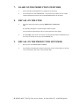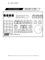
1
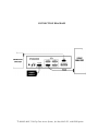
12843 Foothill Blvd., Suite D Sylmar, CA 91342 818 898 3380 voice 818 898 3360 fax [email protected] www.dnfcontrols.com Model No. 4000CL-MAV-PBIO (&4000CL-MAV-T-PBIO) 250 CLIP FAST ACCESS SYSTEM with Peripheral Bus Interface Option Sony DP Protocol for SONY MAV-555 Video Servers USER MANUAL 1 4000CL-MAV, 250 Clip Fast Access System, for Sony MAV-555, with PBIO option Table of Contents 1. REVISION HISTORY 4 GETTING STARTED . . . 5 2. 5 5 5 6 6 6 8 3. 4. 5. 6. 7. 8. 9. 10. SYSTEM DESCRIPTION FEATURES DEFINITIONS SYSTEM INSTALLATION a. ST300-S/SM, VTR/DDR CONTROLLER b. PRODUCTION SWITCHER VIDEO SERVER SETUP LOAD A CLIP LEARN ON THE ST300 LEARN ON THE PRODUCTION SWITCHER RECALL ON THE ST300 RECALL ON THE PRODUCTION SWITCHER TRIGGERS FROM THE PRODUCTION SWITCHER 8 9 9 9 10 ADVANCED FEATURES . . . 11 11. 12. 11 12 12 12 12 12 13 13 13 14 13. 14. CREATE NEW CLIPS TRIMMING A CLIP a. SETTING THE IN (OUT) POINT b. VIEW THE IN (OUT) POINT c. CLEARING AN IN (OUT) POINT d. TRIM CLIPS VIEW CONTENTS OF CUE POINT TRANSFERRING CUELIST a. TRANSMIT CUE LIST FUNCTION b. RECEIVE CUELIST FUNCTION 2 4000CL-MAV, 250 Clip Fast Access System, for Sony MAV-555, with PBIO option REFERENCE . . . 15 15. 16. 17. 15 17 18 18 18 18 18 19 20 18. SETUP MENU FUNCTION TABLE SPECIFICATIONS ST300 RS422 SERIAL CONNECTOR POWER CONNECTOR AUX CONNECTOR (PBUS IN) RS422 SERIAL CONNECTOR GPI IN/OUT CONNECTOR KEY LAYOUT Manual Version.............................................................3.1 040303 Document No.....…........ 4000CL-MAV-PBIO_User_ Manual.doc 3 4000CL-MAV, 250 Clip Fast Access System, for Sony MAV-555, with PBIO option 1. REVISION HISTORY 120602 Rev. 3.0 Added GPI’s 040303 Rev. 3.1 Added Key Layout 4 4000CL-MAV, 250 Clip Fast Access System, for Sony MAV-555, with PBIO option Getting Started . . . 2. SYSTEM DESCRIPTION NOW, production switchers can load & play video clips on Sony MAV DDRs. Use the EMEM or SNAPSHOT Learn & Recall functions of the production switcher to load and play a video clip from a Recall or timeline. Use the Run and Trigger functions of the production switcher to Play, Stop or Recue the video clip. Instantly load a video clip at the press of a button. Instantly load a FILL clip & KEY clip at the press of ONE button, then play out both channels in sync. LOOP up to 4 channels. Control up to 4 video channels individually or ganged. FEATURES The 4000CL-MAV-PBIO, 400 Clip Instant Access System consists of the ST300-SSM with Cliplist software. With this Option, the ST300 has 4 Peripheral Device Addresses, one for each VTR that it controls. This allows the production switcher to control any and all VTRs connected to the ST300. Upon receipt of the Learn command from the production switcher, the ST300 saves the CLIP IDs of the currently loaded clips, the current time of each clip, the VTRs they are loaded on, and the current GANG mode, into the appropriate Cue Point. When the Recall command is received, the ST300 loads the “Learned” Clips onto the “Learned” VTRs, cues the Clip to the “Learned” time, then restores the “Learned” GANG mode. The Trigger function on the production switcher puts the selected VTRs into Play, Stop, Recue or other available modes. DEFINITIONS Throughout this document, “Video Server” refers to the MAV-555. The ST300-S/SM as the ST300. Words surrounded by brackets, for example, [ENTER], are keys on the ST300. [XXX] + [XXX] means hold the two keys down simultaneously. “Softkeys” are the row of keys directly below the display that perform multiple functions in MENU and other modes. 5 4000CL-MAV, 250 Clip Fast Access System, for Sony MAV-555, with PBIO option 3. SYSTEM INSTALLATION a. b. ST300-S/SM, VTR/DDR CONTROLLER 1) Plug one end of a 9-conductor, RS422 serial cable into the 9-pin connector (VTR 1, 2, 3 or 4) on the rear of the ST300. Plug the other end of the cable into the 9-pin REMOTE connector on the Video Server. 2) Connect the +5, +12, -12 VDC POWER SUPPLY into the POWER connector on the rear of the ST300. Plug the Power Supply into an outlet, 90 VAC to 240 VAC. 3) Check SETUP MENU prior to using the ST300 to confirm proper Record mode and other User settable modes. PRODUCTION SWITCHER 1) Connect a standard cable (RS422, 9-pin serial cable) to the “AUX” connector on the rear of the ST300. Connect the other end of the cable to the Peripheral Bus Connector on the production switcher. (Communication Format- 38.4K, N, 8,1) 2) The ST300 has 4 Peripheral Device Addresses, one for each VTR that it controls. To set the Device Address for each VTR: a) Press [MENU] and turn the Wheel until “Peripheral Address” is displayed. b) Press VTR[1], VTR[2], VTR[3] or VTR[4] to select a VTR. c) Assign a Peripheral Device Address for that VTR, from 0 to 23, by entering the desired address using the numeric keypad. NOTE: Address 24 or greater will turn PBIO off. d) 3) Select the next VTR, and then assign a Peripheral Device Address for it. Each VTR must have its own unique address. To select a Production Switcher type (Default = Grass Valley Group). a) Press [MENU] and turn the Wheel until “SWITCHER” is displayed. b) Press the Softkeys to toggle between Sony and Grass Valley. 4) For version 3.0 hardware, there is an option to set Parity to match the parity of the production switcher. In hardware versions 2.0 and 2.1, this option is not offered, as the hardware automatically adjusts for the parity. 5) When done, press [ESC] to exit the MENU. 6) Configure the production switcher: Enable the Peripheral Bus. Enable the Peripheral Device Addresses assigned to the ST300. Enable the appropriate Learn/Recall levels. Enable the Timeline or Recall Trigger function. 6 4000CL-MAV, 250 Clip Fast Access System, for Sony MAV-555, with PBIO option CONNECTION DIAGRAM 7 4000CL-MAV, 250 Clip Fast Access System, for Sony MAV-555, with PBIO option 4. 5. VIDEO SERVER SETUP a. The SONY MAV unit must have the following or higher software versions: V1.1 b. Clips loaded from the front panel of the MAV will not be displayed on the ST300. c. SETUP MENU/RECORD MODE. Crash and Lockout are the only modes supported. LOAD A CLIP a. Select VTR. Connection must be to the Player port in order to load existing clips. b. Press [CLIP LIST]. The CLIP LIST indicator will turn on. The display prompts: “WHEEL-scroll files, ENTER-enter file ID” c. Turn the Wheel to scroll through the list of available CLIPs. OR ENTER a numeric file ID, using the numeric keypad. 6. d. Press [LOAD] to load the desired clip. e. Repeat steps a - d until clips are loaded into the desired VTRs. Set the GANG mode, if required. (Refer to the Function Table for Details.) f. Press [ESC] at anytime to exit CLIP LIST. LEARN ON THE ST300 a. LOAD a clip as described above on the ST300. b. Select the desired Cue Point by pressing [NEXT CUE], [LAST CUE]. OR By manually entering the Cue Point using the numeric keypad. The selected Cue Point number is shown on the bottom line of the display. c. Press [SHIFT] + [MARK] to initiate the LEARN. The ST300 will save loaded CLIP ID and current IN time to the selected Cue Point. The display shows: Select VTR: Mark-Learn, ESC-Cancel d. Press VTR[1], VTR[2], VTR[3] or VTR[4] to select the VTRs. e. Press [MARK]. The ST300 will: LEARN (save) the current configuration, which consists of: Cue Point, CLIP IDs, In Times and Ganged VTRs. 8 4000CL-MAV, 250 Clip Fast Access System, for Sony MAV-555, with PBIO option 7. 8. LEARN ON THE PRODUCTION SWITCHER a. Select and enable the Peripheral Device Addresses for the ST300. b. Do a LEARN to the desired REGISTER. The ST300 will: LEARN (save) the VTR#, loaded CLIP ID and current IN time to the REGISTER number in the ST300. RECALL ON THE ST300 a. Select the desired Cue Point by pressing [NEXT CUE], [LAST CUE]. OR By manually entering the Cue Point using the numeric keypad. The selected Cue Point number is shown on the bottom line of the display. b. 9. Press [LOAD] on the ST300. The ST300 will automatically load the LEARNED clip on the selected VTR and cue the clip to the LEARNED time. RECALL ON THE PRODUCTION SWITCHER a. RECALL the desired REGISTER NUMBER. b. The ST300 will automatically load the Learned clips on the Learned VTRs, cue the clips to the Learned time, then set the Learned GANG mode. 9 4000CL-MAV, 250 Clip Fast Access System, for Sony MAV-555, with PBIO option 10. TRIGGERS FROM THE PRODUCTION SWITCHER Firing a trigger, using either the Timeline or Run function on the production switcher, causes the ST300 to put the Video Server into the following modes, based upon the trigger value: GRASS VALLEY GROUP Trigger Value 0 1 2 3 4 5 6 or greater Mode Play Recue to beginning of clip Slo-mo using ST300 Preset Speed Reverse Play Still Frame None Play SONY Trigger Value 0 1 2 3 4 5 6 or greater Mode Recue to beginning of clip Play Slo-mo using ST300 Preset Speed Reverse Play Still Frame None Play To control more than one VTR, enable the Peripheral Device Address for the required VTRs. The Trigger will be sent to the enabled devices. OR GANG the required VTRs on the ST300. See the Menu Table for GANG instructions. Enable the Peripheral Device Address for one of the GANGed VTRs. The Trigger will be sent to the enabled VTR. The other VTRs in the GANG will perform the same action. 10 4000CL-MAV, 250 Clip Fast Access System, for Sony MAV-555, with PBIO option Advanced Features . . . 11. CREATE NEW CLIPS NOTE: Record duration must be set BEFORE creating a new clip. a. Press [SHIFT] + [RECORD]. The first line of the display shows current record duration. The second line of the display prompts “Enter record length.” b. Enter the desired record length using numeric keypad. c. Press [ENTER] to save the entered time and exit. OR Press [ESC] to exit without saving. NOTE: Default record duration is 30 minutes. d. Select VTR. Connection must be to the Recorder port on MAV-555 to create a clip. e. Press [CLIP LIST]. The CLIP LIST indicator will turn on. The display prompts: The display will show: “Enter New File Name.” f. Enter numeric CLIP ID up to 8 characters using the numeric keypad. g. Press [LOAD] to create the selected CLIP ID. OR Press ESC to exit at anytime. NOTE: The only functions available for new clips are RECORD and STOP. In order to playback a newly recorded clip, you must reload it on a Player port. 11 4000CL-MAV, 250 Clip Fast Access System, for Sony MAV-555, with PBIO option 12. TRIMMING A CLIP a. SETTING THE IN (OUT) POINT 1) Press [IN] ([OUT]). The IN (OUT) indicator turns on. The display shows: “IN (OUT) xx:xx:xx:xx,” where xx:xx:xx:xx is the saved time. OR Press [SHIFT] + [IN] ([OUT]) to manually enter a new IN (OUT) time. 2) Press [ENTER] to save the entered time. OR Press [ESC] to exit without saving. NOTE: When manually entering IN and OUT points, they are always marked based on tape time, not LTC, no matter what time mode is selected. b. c. VIEW THE IN (OUT) POINT 1) When the IN (OUT) indicator is on, Press [IN] ([OUT]) to view the existing IN (OUT) Point. 2) While viewing the IN (OUT) Point: Press [MARK] to overwrite the saved time with the current time. Press [RECUE] to search to the IN (OUT) point. CLEARING AN IN (OUT) POINT Press and hold [DEL] then press and release [IN] ([OUT]). The IN (OUT) indicator turns off. d. TRIM CLIPS 1) LOAD the clip to be trimmed. 2) Mark IN and OUT points as described above. 3) Press [SHIFT] + [TRIM]. The display prompts “Enter new file name.” 4) Enter new file name (up to 8 characters) using the numeric keypad. 5) Press [ENTER] or [LOAD] to save the new CLIP ID. OR Press [ESC] to exit without saving. If the saving is successful, the new clip is created. The beginning of the clip is the marked IN point and the end of the clip is the OUT point. The new clip can be loaded using the CLIP LIST function. Upon saving the new clip, marked IN and OUT points are cleared. NOTE: Do not create trimmed clips with a duration of less than 18 frames. 12 4000CL-MAV, 250 Clip Fast Access System, for Sony MAV-555, with PBIO option 13. VIEW CONTENTS OF CUE POINT a. Use [NEXT CUE] or [LAST CUE] to access Cue Point. Contents loaded at this Cue Point (CLIP ID) will be displayed. OR b. Use numeric keypad to enter Cue Point number. Press [ENTER]. Contents are displayed. 14. TRANSFERRING CUELIST a. TRANSMIT CUE LIST FUNCTION The TRANSMIT CUELIST function allows you to transmit your list of Cue Points to a PC, using the provided utility software on the PC, or to another ST300. 1) TO TRANSMIT CUE POINTS TO THE ST300 a) Connect the VTR4 connector on the rear of the ST300 to the VTR4 connector of the receiving ST300, using an RS422 9-pin cable with TX and RX lines crossed. (A “turnaround” cable) b) Press [MENU] and scroll the wheel to “Transmit CUE List? YES=Enter, Exit=ESC.” c) Press [ENTER] to start transmitting. The Display shows “Waiting to transmit.” d) When the Receiver is ready, transfer starts automatically. The Display now shows “Transmitting cuelist.” e) After the transfer is over, the display shows “Transfer is over” for one second, then shows “Waiting to transmit” again. f) Connect another ST300 to transmit the list again. OR Press [ESC] twice to exit. 2) TO TRANSMIT CUE POINTS TO THE PC a) Connect the VTR4 connector on the back of the ST300 to one of the COM ports on the PC using a RS422 to RS232 adapter. b) Repeat steps b-f of the TO TRANSMIT CUE POINTS TO THE ST300 section. 13 4000CL-MAV, 250 Clip Fast Access System, for Sony MAV-555, with PBIO option b. RECEIVE CUELIST FUNCTION The RECEIVE CUELIST function allows you to receive your list of Cue Points from a PC or from another ST300. 1) 2) TO RECEIVE CUE POINTS FROM THE ST300 a) Connect the VTR4 connector on the back of the ST300 from the VTR4 connector of the transmitting ST300 using RS422 9-pin cable with TX and RX lines crossed. (A “Turnaround” Cable) b) Press [MENU] and scroll the wheel to “Receive CUE List? YES=Enter, Exit=ESC.” c) Press [ENTER] to start receiving. The Display shows “Waiting to receive.” d) When the Transmitter is ready, transfer starts automatically. The Display now shows “Receiving cuelist.” e) After the transfer is over the display shows “Done-Success! Press any key…” f) Press any key. The display shows “Receive cuelist?” message. g) Press [ESC] to exit the MENU mode. TO RECEIVE CUE POINTS FROM THE PC a) Connect the VTR4 connector on the back of the ST300 to one of the COM ports on the PC using RS422 to RS232 adapter. b) Repeat steps b-g of the TO RECEIVE CUE POINTS FROM THE ST300 section. 14 4000CL-MAV, 250 Clip Fast Access System, for Sony MAV-555, with PBIO option Reference . . . 15. SETUP MENU Press [MENU]. The MENU indicator will turn on. Turn the Wheel to select item to change. Press [MENU] OR use the Softkeys to change the desired mode for that option. Turn the Wheel at anytime to select another item. Press [ESC] at anytime to exit SETUP MENU. The MENU indicator will turn off. MENU MODES RECORD WIND MODE (Turning Wheel Clockwise) Press [MENU] to select the desired record mode: Lockout, Crash (Full). Press Softkey to select: HOLD (Fast wind is maintained only while key is depressed.) OR LATCH (Fast wind is initiated and maintained with momentary key press.) Select fast wind speed (3.9 to 23.7) by pressing Softkey below SPD. SLOMO ST300 display shows: (Non T-Bar version) ST300 display shows: (T-Bar version) SLOMO with: WHEEL SpdRange Preset SLOMO with: TBAR Wheel Preset SpdRange NOTE - The T-BAR has a fixed speed range of 0 Æ +200 with a detent at +100 % play speed. Press Softkey [TBAR] (or [WHEEL]) to toggle between them. For Wheel only: Press Softkey [SPDRANGE] to select SLOMO speed ranges. Press Softkey to select: 0 Æ +200 OR -100 Æ +200. Press Softkey [BACK] to return to SLOMO MENU. Press [ESC] to exit OR turn the Wheel to select another item. For Wheel only: Press Softkey [PRSET] to select the SLOMO Preset Speed Mode. Press Softkey [UPDATE]. When exiting SLOMO mode, the last used speed is saved in the Preset Speed register. Press Softkey [STATIC]. The Preset Speed register is NOT updated when exiting SLOMO mode. It is only changed by [SHIFT] + [SLOMO] (PRESET SLOMO). 15 4000CL-MAV, 250 Clip Fast Access System, for Sony MAV-555, with PBIO option ST300 SETUP ST300 SETUP Clear Cues SetDefault Press Softkey beneath ClearCues to clear all Cue Points to 00:00:00:00. Press Softkey [YES] when asked “Are You Sure?” Press Softkey beneath SetDefault to set ST300 to default settings. Press Softkey [YES] when asked “Are You Sure?” DISPLAY SOFTWARE VERSION The version number for the currently installed software is displayed. PARITY In hardware version 3.0 only, set the parity to the same as the switcher. For hardware versions 2.0 and 2.1, no adjustment is provided or required. RECORD Press Softkey to select single button or 2-button record. RECORD = [REC] Only OR [REC] + [PLAY]. PBIO ADDRESS SWITCHER TYPE TRANSMIT CUELIST RECEIVE CUELIST Select to match the switcher output. (ALL hardware versions) Select to match the switcher type. (ALL Hardware versions) Transmit cuelist to another ST300 or to a PC. Receive cuelist from another ST300 or PC. 16 4000CL-MAV, 250 Clip Fast Access System, for Sony MAV-555, with PBIO option 16. FUNCTION TABLE Function GOTO ENTERED TIME Key Press [SHIFT] + [RECUE] Description Search the VTR to the manually entered time. Use the ST300 numeric keypad. Press [ENTER] or [RECUE]. FFWD [FFWD] Press and HOLD to shuttle. Release key to stop. Set WIND Speed in MENU. JOG [JOG] Select JOG mode and enable Wheel. LAST CUE [LAST CUE] Step to the previous Cue Point Location. NEXT CUE [NEXT CUE] Step to the next Cue Point Location. RECORD [REC] Places VTR into the Record mode selected by RECORD MODE in the SETUP MENU. Press [RECORD] or [RECORD] + [PLAY]. REWIND [RWD] Press and HOLD to shuttle. Release key to stop. Set WIND Speed in MENU. SHUTTLE [SHUTTLE] Select SHUTTLE mode and enable Wheel. SLOMO [SLOMO] Press [SLOMO] to slo-mo the VTR. Turn the Wheel (or move the T-Bar if available) to change the play speed. Press SLOMO] to STILL frame. OR Press any transport key to exit SLOMO. SLO-MO SPEED PRESET [SHIFT] + [SLOMO] For WHEEL ONLY: Press [SHIFT] + [SLOMO] to preset the slo-mo speed. Turn the Wheel to select desired speed. Press [ESC] or any transport key to exit. STOP [STOP] Press once to STILL frame VTR. Press again to put VTR into STOP mode. GANG VTRs [SHIFT] + [VTR #1] OR [SHIFT] + [VTR #2] OR [SHIFT] + [VTR #3] OR [SHIFT] + [VTR #4] Press and Hold [SHIFT]. Then when lights go out, press VTR keys to include in the gang. Press [SHIFT] to escape gang setup mode. Flashing LED indicates VTR or HDD being monitored for status. TIME MODE SELECT [TIME MODE] Press to toggle between Timecode (TC), VITC (VT) or Tape Timer (TM) display modes. 17 4000CL-MAV, 250 Clip Fast Access System, for Sony MAV-555, with PBIO option 17. SPECIFICATIONS ST300 Power: 90 VAC to 265 VAC adapter supplied with IEC connector Size: (L” x W” x H”) 12” x 6” x 1.5” (front) 3.0” (rear) Weight: 4 lbs. Rear Panel Connectors: VTR1, VTR2, VTR3, VTR4 … All DB9F GPI......................................….. DBF15F Power....................…................ DB9M Aux .............................…......… DB9F Display: Easy to read 2-line, back-lit LCD display (User adjustable contrast) Jog/Shuttle Wheel: With mechanical detents Optional “T”-bar: Slo-mo 0-200% of Play Speed RS422 SERIAL CONNECTOR 9-Pin D-Type, Female Pin # 1 2 3 4 5 Frame Ground Receive A Í Transmit B Î Transmit Common Spar 6 7 8 9 Receive Common Receive B Í Transmit A Î Frame Ground 6 7 8 9 +5 VDC Ground Ground Ground POWER CONNECTOR 9-Pin D-Type, Male Pin # 1 2 3 4 5 +5v DC +5v DC Ground +12 VDC –12 VDC AUX CONNECTOR (PBUS IN) RS422 SERIAL CONNECTOR 9-Pin D-Type, Female (DB9F) Pin # 1 2 3 4 5 Frame Ground No Connection Receive B Í Common Spare 6 7 8 9 Common No Connection Receive A Í Frame Ground 18 4000CL-MAV, 250 Clip Fast Access System, for Sony MAV-555, with PBIO option GPI IN/OUT CONNECTOR 15-Pin D-Type, Female (DB15F) Pin # 1 2 3 4 5 6 7 8 GPI 1 Out GPI 2 Out GPI 3 Out GPI 4 Out GPI 5 Out GPI 6 Out GPI 7 Out Ground Pin# 9 10 11 12 13 14 15 GPI 1 In – Play GPI 2 In – Stop GPI 3 In – Recue GPI 4 In – Next cue GPI 5 In – Last cue GPI 6 In – Recall GPI 7 In 19 4000CL-MAV, 250 Clip Fast Access System, for Sony MAV-555, with PBIO option 18. KEY LAYOUT 20 4000CL-MAV, 250 Clip Fast Access System, for Sony MAV-555, with PBIO option