1
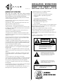
INSTALLATION INSTRUCTIONS
SONAMP 1230 OWNER'S MANUAL
PROFESSIONAL MATRIX POWER A M P L I F I E R
PN.33-2159 6.01
IMPORTANT SAFETY INSTRUCTIONS
17. Damage Requiring Service - The appliance should be
serviced by a qualified service personnel when:
When using your Sonamp® 1230, basic safety precautions
should always be followed to reduce the risk of fire, electric
shock, and injury to persons, including the following:
A. The power-supply cord or the plug has been damaged
B. Objects have fallen, or liquid has been spilled into
the appliance
1. Read instructions – All the safety and operating instructions should be
read before the appliance is operated.
C. The appliance has been exposed to rain
D. The appliance does not appear to operate normally or
exhibits a marked change in performance
2. Retain instructions – The safety and operating instructions should be
retained for future reference.
E. The appliance has been dropped, or the
enclosure damaged
3. Heed warnings – adhere to all warnings and precautions listed on the
appliance and in the operating instructions.
18. Servicing - The user should not attempt to service the appliance beyond
that described in the operating instructions. All other servicing should be
referred to qualified service personnel.
4. Follow instructions – Follow all operating instructions.
5. Water and moisture – The appliance should never be used next to water;
for example, near a bathtub, kitchen sink, laundry tub, in a wet basement, or
near a swimming pool, etc.
19. Lifting – Do not attempt to lift the Sonamp® 1230 without
assistance. Improper lifting of this 35 lb. unit can cause personal injury.
6. Carts and stands – The appliance should be used only with a cart or
stand that is recommended by the manufacturer.
20. Power requirement – Do not connect the Sonamp® 1230 to the
accessory outlet of another component. A minimum 15 amp grounded wall
outlet is required.
7. An appliance and cart combination should be moved with care. Quick
stops, excessive force, and uneven surfaces may cause the appliance and cart
combination to overturn.
21. Storms – To prevent damage to components, unplug all electronic
equipment during thunderstorms.
8. Caution: To prevent electric shock, do not use the Sonamp (polarized)
plug with an extension cord, receptacle, or other outlets unless the blades
can be fully inserted to prevent blade exposure.
CAUTION
9.Ventilation – The appliance should be situated so that its location does
not interfere with its proper ventilation. For example, the appliance should
not be situated on a bed, sofa, register, or similar surface that may impede
the flow of air through the ventilation openings.
RISK OF ELECTRIC SHOCK
DO NOT OPEN
10. Heat – The appliance should be situated away from heat sources such as
radiators, heat registers, stoves, or other appliances (including amplifiers)
that produce heat.
CAUTION: TO REDUCE THE RISK OF ELECTRIC SHOCK,
DO NOT REMOVE COVER (OR BACK)
NO USER SERVICEABLE PARTS INSIDE
REFER SERVICING TO AUTHORIZED
SERVICE PERSONNEL.
11. Power sources – The appliance should be connected to a power supply
only of the type described in the operating instructions or as marked on the
appliance.
12. Grounding or polarization – Grounding or polarization are the precautions that should be taken so that these attributes of an appliance are not
defeated.
The lighting flash with arrowhead symbol, within an
equilateral triangle, is intended to alert the user to the
presence of uninsulated dangerous voltage within the
product's enclosure that may be of sufficient magnitude
to constitute a risk of electric shock to persons.
13. Power-Cord Protection - Power supply cords should be
routed so that they are not likely to be walked on or pinched by items placed
upon or against them, paying particular attention to cords at plugs, convenience receptacles, and the point where they exit from the appliance.
The exclamation point within an equilateral triangle is
intended to alert the user to the presence of important
operating and maintenance (servicing) instructions in the
literature accompanying the appliance.
14. Cleaning - The appliance should be cleaned only as recommended by
the manufacturer.
15. Non-Use Periods- The power cord of the appliance should be unplugged
from the outlet when left unused for a long period of time.
WARNING: TO PREVENT FIRE OR SHOCK HAZARD,
DO NOT EXPOSE THIS APPLIANCE TO
RAIN OR MOISTURE.
16. Object and Liquid Entry - Care should be taken so that objects do not
fall and liquids are not spilled through the opening of the enclosure.
WARNING
MOVE WITH CARE
1
INTRODUCTION
• Speaker wires. These may be unterminated (tinned bare wire at
connections) or spade, banana, or pin connectors. Gold plated
connectors are preferred to resist oxidation.
Thank You for purchasing the Sonamp® 1230. Sonance has
taken the versatile Sonamp® 1250 and improved it by adding
more features, which makes the Sonamp® 1230 the most
versatile and reliable multi-channel amplifier available. Most
importantly, we listened to installers and end users and added
features that they wanted.
• LS1 and LR1 balanced line-level sender and receiver
(optional). If the amplifier is placed more than 20 feet from the
source or preamplifier, the balanced sender and receiver provide a way to send low level audio signals long distances and
near sources of noise interference without introducing noise or
suffering high frequency roll-off (See Fig. 6 for example).
ADDITIONAL AMPLIFIERS
If additional Sonamp® 1230's are used, we recommend
separate 15 amp circuits for each amplifier due to the
enormous power capability and requirements of this product.
Non-buffered LINE OUT connections for left, right, and
auxiliary channels are provided. Within the limits of available
mains power, any number of additional Sonamp 1230
amplifiers may be daisy chained for larger installations.
INSTALLATION
Unpacking
Save the carton and polystyrene inserts for future safe transport
in case the amplifier is moved or the unit requires shipping
for repair.
ASSOCIATED COMPONENTS
A music reproduction system is only as good as its weakest
link. To avoid disappointment, your Sonamp® 1230 should be
used with other components of the highest caliber.
The Sonamp® 1230 is compatible with most high quality preamplifiers, tuners, CD/DVD players, and Mini Disc decks; as well as
better in-wall and cabinet mounted speakers from Sonance
and other reputable manufacturers.
Before proceeding with installation, locate the serial number
on the real panel of the unit and note it here for future reference :
CARE AND MAINTENANCE
CAUTION: Do not attempt to lift the Sonamp 1230
without assistance. Improper lifting of this 35 lb. unit can cause
personal injury.
S/N:_________________________________________
Placement
Retain the safety and operating instructions for future reference.
1. Follow all warnings and instructions in this manual and
marked on the product.
Place the Sonamp® 1230 on a level surface, in an upright
position, out of direct sunlight and away from windows through
which rain may enter.NOTE: The amplifier must always rest on its
four feet to allow ventilation or it will sustain damage.
2. Any service or repair required must be performed by
qualified, factory authorized personnel.
3. To clean your Sonamp 1230, use a soft brush,“canned air,” or
wipe exterior surfaces with a damp cloth. Never use any
cleaners or solvents.
Situate the amplifier away from heat sources such as hot air
ducts or radiators. Be sure that the amplifier is adequately
ventilated by convection or suitable cabinet fans. CAUTION:
The Sonamp® 1230 requires four inches of clearance on the top
and all sides. Never place any object on or against the
amplifier. Never operate the amplifier on a carpeted surface as
this will compromise ventilation. When the amplifier is
installed in any cabinet, the front or back must be open during
operation. Alternately, install fans in the cabinet to assure
continuous ventilation.
4. Do not use this product in a high humidity environment
or near water, for example a wet basement, wet bar, or swimming pool.
5. If the electrical service is subject to frequent sags, spikes,
and brownouts, a power conditioner designed for use with
high fidelity equipment may be employed to protect the
Sonamp 1230.
Power Connection
The Sonamp® 1230 uses a 14 gauge EIA standard 120 volt
grounded power cable (provided). Due to the power requirement of this amplifier, it is not advised that this cable be replaced
with another of unknown quality.Connect the power cable to a 15
amp or 20 amp grounded wall outlet.Never attempt to operate the
amplifier from the accessory outlet of another component.
SYSTEM CONFIGURATION
Read Getting The Most From Your Sonamp 1230 and plan your
installation configuration. Due to the flexibility of the Sonamp
1230, the installation should be carefully planned to avoid errors.
Start by drawing a diagram of the system, like the examples in this
manual.Plan the settings and connections to achieve your objective.
Sensitive source components should be isolated from the
Sonamp® 1230 with appropriate power conditioning to
minimize hum from the amplifier’s power supply.
Verify that you have all of the parts and tools required for the
installation:
Speaker Connection
Always turn off power and unplug the amplifier before making
source signal or speaker connections.
• High fidelity interconnect cables such as Sonance Silver
MediaLinQ OFC Interconnects.
Use quality speaker wire such as Sonance Silver or Gold
2
A
3
2
4
®
SONAMP 1230
POWER
ACTIVE
A.C. ON
1•2
3•4
5•6
7•8
9 •10
11•12
PROTECTION
1
A. FRONT PANEL
1. POWER SWITCH
2. ACTIVE L.E.D.
3. POWER L.E.D.
4. FAULT INDICATORS
11 10 9
8
6
5
®
SONAMP 1230
AUTO-ON
LEFT
DIRECT
LEFT
RIGHT
AUX
RIGHT
CH. 1
DIRECT
LEFT
RIGHT
AUX
DIRECT
LEFT
RIGHT
AUX
DIRECT
LEFT
RIGHT
AUX
CH. 2
CH. 3
VOLUME
DIRECT
LEFT
RIGHT
AUX
DIRECT
LEFT
RIGHT
AUX
CH. 5
CH. 4
VOLUME
DIRECT
LEFT
RIGHT
AUX
CH. 6
DIRECT
LEFT
RIGHT
AUX
CH. 7
CH. 8
VOLUME
DIRECT
LEFT
RIGHT
AUX
DIRECT
LEFT
RIGHT
AUX
DIRECT
LEFT
RIGHT
AUX
CH. 9
CH. 11
CH. 10
VOLUME
DIRECT
LEFT
RIGHT
AUX
VOLUME
AUTO-ON
INPUT
EXTERNAL VOLTAGE
+
–
CH. 12
5-24V AC/DC
VOLUME
OUTPUT
+
–
Caution: For Continued Protection Against Fire Hazard Use Only Same Type And Rating Fuses. Disconnect Power Supply Before Changing Fuse. Do Not Expose This Unit To Rain Or Moisture. No User Servicable Parts Inside. See Operating Manual Before Using.
Mise en garde: Afin d' éviter toute possibilité d' incendie, n´ utiliser que le même type de fusibles. Débrancher l´appareil avant de changer les fusibles. Ne pas exposer cet appareil å l ire ou å l´humidité. Ne pas ouvrir l´appareil. Lire attentivement la notice avant utilisation.
AUX
BUS INPUT
NORMAL
BRIDGED
NORMAL
BRIDGED
NORMAL
BRIDGED
NORMAL
BRIDGED
NORMAL
BRIDGED
NORMAL
BYPASS
TRIGGER
MODE
BRIDGED
˜ FUSE
F 10A T 250V
FUSE
12VDC
BUS OUTPUT
BRIDGED
BRIDGED
8Ω Min.
BRIDGED
8Ω Min.
8Ω Min.
BRIDGED
BRIDGED
8Ω Min.
8Ω Min.
GROUND
LIFT
ON
120V 60Hz
˜
OFF
SN:
+
+
+
+
+
+
+
CAUTION
RISK OF ELECTRIC SHOCK
DO NOT OPEN
RIGHT
–
AUX
–
–
–
–
–
–
CHANNEL
CHANNEL
CHANNEL
CHANNEL
CHANNEL
CHANNEL
CHANNEL
CHANNEL
CHANNEL
CHANNEL
CHANNEL
CHANNEL
1
2
3
4
5
6
7
8
9
10
11
12
7
3
4
2
1
1200VA
12
13
B
B. REAR PANEL
1. SPEAKER TERMINALS (12)
2. BRIDGING SWITCH (6)
3. INPUT LEVEL CONTROL (12)
4. SOURCE SELECTION SWITCH (12)
5. BUS LINE-IN JACKS (3)
6. DIRECT INPUT SOURCE JACK (12)
7. LINE-OUT JACKS (3)
8. TRIGGER SELECT SWITCH
9. AUTO-ON SENSITIVITY CONTROL
10. CONTROL VOLTAGE INPUT
11.CONTROL VOLTAGE OUTPUT
12. ~ POWER FUSE RECEPTACLE
13. ~ POWER CORD RECEPTACLE
3
SONANCE
SAN CLEMENTE, CA
92672-7531
LEFT
BRIDGED
8Ω Min.
Power Trigger Controls
MediaLinQ™ cable to assure optimum sound reproduction.
Small gauge or inferior quality wire will degrade imaging,
diminish bass reproduction, and add a generally congested
quality to music. Always check local building codes before
installing wire in walls or ceilings.
The Sonamp® 1230 may be automatically activated by an input
signal, low voltage trigger, or manual pushbutton. It also
provides a 12 volt DC output to trigger other components.
Auto-On Control
Wires may be terminated with banana plugs for convenience if
connections will be changed frequently. Any connector should
be gold plated to prevent oxidation, which degrades sound
quality. The binding posts on the Sonamp® 1230 also accept
twisted bare wire ends through the 45º opening in their center
shafts. Do not overtighten shafts. Tinning the bare copper wire
is recommended. As an option, use contact enhancer on mating
surfaces of connections to retard oxidation and enhance signal
flow. Do not strip more than 1/2”of the jacket from speaker wires.
To use the Auto-On feature, turn the main power switch ON and
slide the TRIGGER switch on the rear panel to the UP
position. Use the SENSITIVITY control to set the minimum
signal level that will activate the amplifier. In this mode, the
amplifier will automatically turn off after 8 minutes of no input
signal at any of the 12 channel inputs. The Auto-On mode disables the other two triggering modes.
Voltage Control
When the TRIGGER switch is set to EXTERNAL VOLTAGE
(the center position) and the main power switch (on the front
panel) is set to ON, the amplifier will be activated by the
presence of AC or DC voltage, from 5 to 24 volts, at the
INPUT connector. The EXTERNAL VOLTAGE mode disables
the other two triggering modes. (DO NOT CONNECT TO
120VAC LINE VOLTAGE)
Always provide sufficient slack in wires to avoid tension or
accidental disconnection. Always contain any excess wire to
prevent tripping hazards.
Source Connection
Always use quality high fidelity interconnect cables such as
Sonance Silver MediaLinQ OFC Interconnects. If source
components are more than 20 feet from the amplifier, use the
LS1 and LR1 balanced line-level sender and receiver to avoid
signal degradation (As shown in Figure 6).
Bypass
If the TRIGGER switch is set to BYPASS (the bottom position)
and the main power switch (on the front panel) is set to ON, the
amplifier will always be active. The BYPASS mode disables the
other two triggering modes.
Plug source components (receiver, preamp, page signal) to the
LINE IN bus inputs at the top center of the amplifier.
Plug dedicated sources (zone output, page signal, video game,
or electronic doorbell) into the DIR (direct) channel inputs if
desired.
Ground lift
The GROUND LIFT switch breaks ground loops that can occur
between source equipment and amplifiers. Set the GROUND
LIFT switch to OFF for most applications. When the Sonamp
1230 is to be used in an equipment rack, set the GROUND LIFT
switch in the ON position. This will isolate the audio circuitry
from the chassis. Thus, the chassis need not be isolated from
the equipment rack with insulator washers.
Plug downstream amplifiers to the non-buffered LINE OUT
bus outputs at the bottom center of the amplifier.
Source Settings
The fourplex DIP switches of the Sonamp® 1230 provides the
most flexible configuration options of any multichannel amplifier. Settings are changed by moving the switches from (ON) to
(OFF):
Status LEDs
AC ON LED – This red LED indicates that the AC power line
cord is plugged into a live AC outlet. If the main AC line fuse
opens, this LED goes out. The main power switch setting does
not impact this LED.
L
Assign to master left channel source
R
Assign to master right channel source
L+R
Mono reproduction of source
AUX
Assign to AUX channel source
DIR
Select dedicated channel input.
Note: It is possible to assign one or all switches as needed (L+R+AUX,
where AUX is the page input for a hallway or waiting room with paging.
ACTIVE LED – This green LED indicates that the amplifier
has been activated via one of the three methods described previously.
PROTECTION LEDs – These amber LED’s light during a fault
condition, one LED for each pair of channels. If one of the
Sonamp 1230’s protection circuits is triggered, the LED will
turn on. If a channel pair encounters a short-circuit event or an
extremely low impedance, the respective LEDs will light (1&2,
3&4, 5&6, 7&8, 9&10, 11&12). All other channel pairs are unaffected. If the heat sink temperature is exceeded because of poor
air circulation or high ambient temperature, a cutoff switch
attached to left and right channels will activate. Each bank
(1&2, 3&4, 5&6 or 7&8, 9&10, 11&12)of a Protect LEDs will
then light to signify a fault. If amplifiers are in Bridged mode,
the Protection Circuitry will sense a short circuit across both
positive speaker terminals and also positive to negative speaker terminal.
Volume Control
The individual channel volume controls are useful to
balance the desired sound levels for various zones, to balance
output from right and left channels to compensate for room
characteristics such as size and ceiling height.Also,by reducing
the Sonamp volume control settings, you compel the source
preamp or receiver volume control to operate in the middle
of its range. do not set the level controls higher than the
maximum level desired. Place tape over the VC hole to prevent
tampering.
4
well as a preset maximum volume level (using the 1230 volume
controls). This capability allows tailoring sound reproduction
to the size and use of each room.
Each time the amplifier is initially plugged in and the main
power switch is turned on, the protection LEDs will light for
approximately 3 seconds while amplifier circuitry is stabilizing.
This prevents spikes and thumps from getting to speakers. Any
time the protection circuits are triggered, turn the main power
switch off before troubleshooting for shorted output connections
or faults with source components.
If one room requires more power, a pair of high output
channels may be configured by bridging two pairs of channels.
Commercial Background Music System with Paging Capabilities
(Figure 2)
Bridging Channels
Bridging a pair of 30W channels to yield one 60W channel is a
simple operation of moving the toggle switch from the
NORMAL position to the BRIDGED position. This operation
subsequently disables the routing/switching function of the
channel directly below the bridged channel. This would apply
to even numbered channels (2,4,6,8,10,12). The dip switch
controls for the BRIDGED channel is directly related to the odd
numbered channels(1,3,5,7,9,11). The bridged channel would
then use both positive speaker binding post connections (red +
terminals) to connect to speakers.(8Ω speakers only) Do not use
double banana plugs for bridged connections.
Features
• 6 Room
• Common Music Source
• Two Zones with AUX Input for Paging Function
Adding a microphone preamplifier connected to the AUX
input provides the capability of mixing the stereo source
with paging. For maximum flexibility, each channel is
individually configurable to use or ignore the AUX input.
Use an AL1/S to mute the audio inputs during paging.
A great application for restaurants, nightclubs,offices,etc.
Note: If possible, adjust the microphone preamp volume level
slightly higher than the other input source.
INSTALLATION SAFETY
When installing the Sonamp 1230, basic safety precautions
should always be followed to reduce the risk of fire,
electric shock, and injury to persons, see the following:
Multiple Zone Music System (Figure 3)
Features
1. Read and understand all instructions.
• 5 Zones are fed from Main System
2. Follow all warnings and instructions in this manual and
marked on the product.
• 1 Zone is a Dedicated system with IR Control of Volume and Input Selections
4. Do not install this product in a high humidity environment
or near water, for example a wet basement, wet bar, or
swimming pool.
Using the Sonance Navigator Harbor, a matrix preamplifier
capable of directing signals to multiple amplifier inputs, or
employing several discrete preamplifiers, the Sonamp 1230
may be configured to provide different program material to all,
or some zones. The main input can drive any channels not
individually connected to sources.
5. Do not defeat the ground pin on the AC cord.
Home Theater and Music System (Figure 4)
3. Any service or repair required must be performed by qualified
factory authorized personnel.
Features
6. Disconnect the AC power to Sonamp® 1230 when wiring or
reconfiguring connections.
• 10 Channels Bridged to 5 channels for 60 watt per channel Theatre Output
• 2 Channels for Second Room Output on Receiver or Separate Input Source
A five channel surround sound system may be configured
from five channels. The five bridged channel configuration
leaves two channels available for stereo reproduction in
other zones.
INSTALLATION EXAMPLES
Diagrams of these examples follow later in this manual. The
following six system examples are only the beginning, with
some imagination, many other variations are possible.
In larger home theaters where high listening levels must be
supported, every channel pair may be bridged, creating six
60 watt channels to support speakers in the LCR (left, center,
right), surround, and subwoofer roles.
A surround sound receiver may be configured to provide
source signal to the Sonamp 1230 for one room, while
independently driving another set of surround speakers with its
internal amplifier.
Basic Background Music System (Figure 1)
Features
• 6 Room
• Common Music Source
• Passive Volume Control at each Zone
Perhaps the simplest configuration of the Sonamp 1230 uses a
single source preamplifier into six sets of stereo speakers, one
pair of speakers per room. The factory default rear panel DIP
switches and toggles are set for this application. This is a single
zone system. Note that each room may have a volume control as
5
Multiple Source/Multiple Zone with Paging (Figure 5)
MAINTAINING YOUR SONAMP 1230
Features
The Sonamp® 1230 does not require periodic maintenance and
has no user serviceable parts inside. Do not remove the top
cover as this will increase your risk of electric shock. To keep
the amplifier clean, use only a soft cloth and never use any
solvents or abrasives. Fingerprints may be removed with a soft
cloth moistened only with a few drops of water.
• 1 Zone is HIGH POWER with Bridged Outputs and IR Control
• 2 Zones are STEREO with Volume Controls
• 4 Zones are MONO with Impedance Matching Volume Controls and Paging
• 1 Zone is STEREO with Volume Control and Paging
• AUX Input for KSU Paging in Selected Zones
SPECIFICATIONS
This configuration shows several rooms in stereo mode while
utilizing mono in selected areas. Note that certain areas receive
the paging signal. Due to its large size, the master bedroom
receives a bridged 4 channels providing 60 watts per channel .
All Channels Driven
Output Power, Stereo mode, RMS: 30 Watts per channel, 12 channels @8Ω
45 Watts per channel, 12 channels @4Ω
60 Watts per channel, 6 channels @8Ω bridged
Major Corporate System (Figure 6)
Features
IHF: Dynamic Power:
49 Watts per channel, 12 channels @8Ω
78 Watts per channel,12 channels @4Ω
• Automatic 2 source Main Music
158 Watts per channel, 6 channels @8Ω bridged
• 8 Speakers on 2 Channels with Impedance Matching Volume Controls and
MONO Function
Dynamic Headroom:
+2.13dB, 12 channels @8Ω
+2.38dB, 12 channels @4Ω
• 4 Zone Keypad System
+4.15dB, 6 channels @8Ω bridged
Total Harmonic Distortion:
• Executive Office controls with option to select from Main Source to Local
0.1% 20Hz-20kHz @8Ω (30 WRMS)
0.25% 20Hz-20kHz @4Ω (45 WRMS)
• AC Power Control of Main Music Sources
THD @ 1kHz less than 0.01% with 8Ω (30 WRMS)
• Key Switch On/Off of Entire System, Auto-On Feature Defeated, 12v control
for AC Switching
THD @ 1kHz less than 0.01% with 4Ω (45 WRMS)
I.M. Distortion (SMPTE 4:1) @8Ω: 0.01% @ 30 Watts
Signal to Noise Ratio:
• AUX Input for KSU Paging in Selected Areas
A specialized installation that includes remote key switch turn
on and usage of multi-zone controllers for individual spaces
with keypad controls. Executive suite is specialized with
main/local source selection and control of entire system.
Restrooms, small vestibules, elevators, and large rooms
arranged in multiple seating areas are some examples of spaces
more appropriate to monaural music. Each of the Sonamp
1230’s 12 channels may be individually configured for monaural reproduction if required to achieve smooth coverage of the
entire musical content of the source.
-100dB below rated output (A-weighted)
Input Sensitivity:
700 millivolt for 30 watts RMS @8Ω
Input Impedance:
20kΩ
Power Consumption:
1440 Watts,
maximum
4Ω full power
1400
Watts
maximum
@ 4 ohms, full power
AC Fuse
15A AGAG
10A
6.5 Watts, standby
Optional Items
A Basic Six Zone System (Figure 7)
Features
• 6 Rooms
• 3 Music Sources
• 3 Video Sources
• Sonance Navigator Master keypads at each zone
This diagram depicts a basic six zone install featuring a
Sonance Navigator Harbor with three audio and three video
inputs feeding a Sonamp 1230 amplifier with voltage turn on,
as well as feeding video to three TVs located in zones two, five
and six.Each of the six zones is controlled by a Sonance Navigator
Master keypad. The source components are controlled by the
Harbor’s Common IR outputs. When only a couple source components are present,the 200VA switched power outlet can be used
to power up these devices. A voltage controlled power strip to
power up more source components is recommended to prevent
overloading of the switched AC outlet. The Control Output of
the Harbor should be used to control the power strip. (Do not
exceed the 100mA rating of the Control Output.)
6
3-space Rack Mount Faceplate
Dimensions:
16-3/4"
x 5-3/4"
10-1/2" x 16-3/4"
x 18" x 15-3/8"
(425mm
x 146mm
(267mm x 425mm
x 457mm)x 391mm)
RMF Dimensions:
38 lbsx(17KG)
19"
5-1/4" x 15-3/8"
(483mm x 133mm x 391mm)
Shipping Weight:
38 lbs (17kg)
TECHNICAL ASSISTANCE
WARRANTY COVERAGE (USA ONLY)
If you have any questions about the operation or installation of
your Sonance Sonamp 1230, please call our Technical
Assistance Department on any business day at:
If, within one (1) year from the date shown on the bill of sale,
the unit fails due to a defect in workmanship or materials,
Sonance will,at its option and at no charge to purchaser,repair or
replace the components of such unit which proves to be defective.
• (800) 582-0772 or (949) 492-7777 from 9 a.m. to 5 p.m., PST
For this warranty to be effective, the bill of sale must show that
the unit was purchased from an authorized Sonance retailer.
This warranty shall apply exclusively to the original purchaser
and shall not apply to units purchased for industrial or
commercial use.
OBTAINING SERVICE
Should your product require repair or service, contact your
authorized Sonance retailer for help, or use the following
procedure:
Furthermore, this warranty shall not apply if:
1. Prior to calling, note the product model number, serial number, purchase date, and original retailer’s name and address.
1. Damage to the unit was caused by accident, abuse, or misuse;
2. Contact our Technical Assistance Department at the
number(s) above and describe the problem. If required, a
Return Merchandise Authorization (RMA) number will be
issued. IMPORTANT: Do not return the unit to Sonance
without first obtaining an RMA number.
3.The unit was not used as outlined in the operating instructions.
2. The unit was opened, modified, or repaired by unauthorized
personnel; or
Exclusions and Limitations
The warranty set forth above is in lieu of all other warranties,
express or implied, of merchantability, fitness for a particular
purpose, or otherwise. The warranty is limited to Sonance
products registered herein and specifically excludes any
damage to any associated equipment, which may result for any
reason from use with this product.
3. If you are directed to return the unit to Sonance for repair,
pack the unit in its original shipping cartons(inner & outer).
Replacement packaging can be obtained from Sonance for a
small charge.
4. Contact United Parcel Service, Federal Express, or RPS to
arrange prepaid (not collect) shipping. Do not use the United
States Postal Service. IMPORTANT: Freight collect shipments
will be refused.
Sonance shall, in no event, be liable for incidental or consequential
damages arising from any breach of this warranty or otherwise.
This warranty gives you specific legal rights, and you may have
other rights, which vary from state to state.
5. Write the Return Merchandise Authorization number on the
outside of the shipping carton.
6. For warranty work, please include a copy of the original bill
of sale inside the package.
Ship the packaged unit to:
Technical Assistance Department
Sonance
212 Avenida Fabricante
San Clemente, CA 92672-7531
7
Figure 1 Single Zone
Factory Default Settings for DIP Switches and toggle switches
of Channel Assignments
INPUT SOURCE
FIXED
CD
PHONO VIDEO2
VIDEO1
TAPE OUTPUT
LEFT
LEFT
RIGHT
RIGHT
ZONE
ZONE
1
VC60RX
VC60RX
Volume Control
Volume Control
LEFT
4
LEFT
RIGHT
RIGHT
ZONE
ZONE
2
5
®
SONAMP 1230
VC60RX
AUTO-ON
LEFT
Volume Control
DIRECT
LEFT
RIGHT
AUX
LEFT
CH. 1
DIRECT
LEFT
RIGHT
AUX
DIRECT
LEFT
RIGHT
AUX
DIRECT
LEFT
RIGHT
AUX
RIGHT
CH. 2
CH. 3
VOLUME
DIRECT
LEFT
RIGHT
AUX
DIRECT
LEFT
RIGHT
AUX
DIRECT
LEFT
RIGHT
AUX
CH. 5
CH. 4
VOLUME
CH. 6
DIRECT
LEFT
RIGHT
AUX
CH. 7
VOLUME
DIRECT
LEFT
RIGHT
AUX
DIRECT
LEFT
RIGHT
AUX
CH. 8
CH. 9
DIRECT
LEFT
RIGHT
AUX
VOLUME
DIRECT
LEFT
RIGHT
AUX
CH. 11
CH. 10
VOLUME
AUTO-ON
INPUT
VOLUME
OUTPUT
+
–
BUS INPUT
NORMAL
BRIDGED
NORMAL
BRIDGED
NORMAL
BRIDGED
NORMAL
BRIDGED
NORMAL
BRIDGED
NORMAL
LEFT
BYPASS
TRIGGER
MODE
5-24V AC/DC
Caution: For Continued Protection Against Fire Hazard Use Only Same Type And Rating Fuses. Disconnect Power Supply Before Changing Fuse. Do Not Expose This Unit To Rain Or Moisture. No User Servicable Parts Inside. See Operating Manual Before Using.
Mise en garde: Afin d' éviter toute possibilité d' incendie, n´ utiliser que le même type de fusibles. Débrancher l´appareil avant de changer les fusibles. Ne pas exposer cet appareil å l ire ou å l´humidité. Ne pas ouvrir l´appareil. Lire attentivement la notice avant utilisation.
AUX
Volume Control
EXTERNAL VOLTAGE
+
–
CH. 12
VC60RX
BRIDGED
˜ FUSE
F 10A T 250V
FUSE
12VDC
BUS OUTPUT
BRIDGED
BRIDGED
8Ω Min.
BRIDGED
8Ω Min.
8Ω Min.
BRIDGED
BRIDGED
8Ω Min.
8Ω Min.
GROUND
LIFT
120V 60Hz
˜
OFF
ON
SN:
+
+
+
+
+
+
+
–
–
–
–
–
–
–
CAUTION
RISK OF ELECTRIC SHOCK
DO NOT OPEN
SONANCE
SAN CLEMENTE, CA
92672-7531
LEFT
BRIDGED
8Ω Min.
RIGHT
RIGHT
AUX
CHANNEL
CHANNEL
CHANNEL
CHANNEL
CHANNEL
CHANNEL
CHANNEL
CHANNEL
CHANNEL
CHANNEL
CHANNEL
CHANNEL
1
2
3
4
5
6
7
8
9
10
11
12
RIGHT
1200VA
ZONE
ZONE
3
LEFT
VC60RX
VC60RX
Volume Control
Volume Control
RIGHT
DIRECT
LEFT
RIGHT
AUX
CH. 1
RIGHT
DIRECT
LEFT
RIGHT
AUX
DIRECT
LEFT
RIGHT
AUX
DIRECT
LEFT
RIGHT
AUX
CH. 2
6
LEFT
CH. 3
VOLUME
DIRECT
LEFT
RIGHT
AUX
CH. 4
VOLUME
DIRECT
LEFT
RIGHT
AUX
CH. 5
DIRECT
LEFT
RIGHT
AUX
CH. 6
DIRECT
LEFT
RIGHT
AUX
CH. 7
VOLUME
DIRECT
LEFT
RIGHT
AUX
DIRECT
LEFT
RIGHT
AUX
CH. 8
CH. 9
VOLUME
DIRECT
LEFT
RIGHT
AUX
CH. 10
DIRECT
LEFT
RIGHT
AUX
CH. 11
VOLUME
CH. 12
VOLUME
Caution: For Continued Protection Against Fire Hazard Use Only Same Type And Rating Fuses. Disconnect Power Supply Before Changing Fuse. Do Not Expose This Unit To Rain Or Moisture. No User Servicable Parts Inside. See Operating Manual Before Using.
Mise en garde: Afin d' éviter toute possibilité d' incendie, n´ utiliser que le même type de fusibles. Débrancher l´appareil avant de changer les fusibles. Ne pas exposer cet appareil å l ire ou å l´humidité. Ne pas ouvrir l´appareil. Lire attentivement la notice avant utilisation.
NORMAL
DIRECT
LEFT
RIGHT
AUX
BRIDGED
NORMAL
BRIDGED
NORMAL
BRIDGED
NORMAL
INDICATED
DIP SWITCH
POSITION
(ON POSITION)
BRIDGED
NORMAL
9
NORMAL
BRIDGED
NORMAL
BRIDGED
BRIDGED
INDICATED
SLIDE SWITCH
POSITION
(BRIDGED POSITION)
Figure 2 Single Zone plus Paging
MICROPHONE PREAMP
OUTPUT
INPUT SOURCE
FIXED
CD
PHONO VIDEO2
VIDEO1
TAPE OUTPUT
LEFT
LEFT
RIGHT
RIGHT
ZONE
ZONE
1
4
LEFT
LEFT
LINE IN
+ AUX
RIGHT
RIGHT
ZONE
ZONE
2
5
LEFT
LEFT
®
SONAMP 1230
AUTO-ON
LEFT
DIRECT
LEFT
RIGHT
AUX
RIGHT
CH. 1
DIRECT
LEFT
RIGHT
AUX
DIRECT
LEFT
RIGHT
AUX
DIRECT
LEFT
RIGHT
AUX
CH. 2
CH. 3
VOLUME
DIRECT
LEFT
RIGHT
AUX
DIRECT
LEFT
RIGHT
AUX
CH. 5
CH. 4
VOLUME
DIRECT
LEFT
RIGHT
AUX
CH. 6
DIRECT
LEFT
RIGHT
AUX
CH. 7
CH. 8
VOLUME
DIRECT
LEFT
RIGHT
AUX
DIRECT
LEFT
RIGHT
AUX
CH. 9
DIRECT
LEFT
RIGHT
AUX
CH. 11
CH. 10
VOLUME
DIRECT
LEFT
RIGHT
AUX
VOLUME
AUTO-ON
INPUT
EXTERNAL VOLTAGE
+
–
CH. 12
5-24V AC/DC
VOLUME
OUTPUT
BUS INPUT
NORMAL
BRIDGED
NORMAL
BRIDGED
NORMAL
BRIDGED
NORMAL
BRIDGED
NORMAL
BRIDGED
NORMAL
˜ FUSE
F 10A T 250V
+
–
Caution: For Continued Protection Against Fire Hazard Use Only Same Type And Rating Fuses. Disconnect Power Supply Before Changing Fuse. Do Not Expose This Unit To Rain Or Moisture. No User Servicable Parts Inside. See Operating Manual Before Using.
Mise en garde: Afin d' éviter toute possibilité d' incendie, n´ utiliser que le même type de fusibles. Débrancher l´appareil avant de changer les fusibles. Ne pas exposer cet appareil å l ire ou å l´humidité. Ne pas ouvrir l´appareil. Lire attentivement la notice avant utilisation.
AUX
BYPASS
TRIGGER
MODE
BRIDGED
FUSE
12VDC
RIGHT
BUS OUTPUT
BRIDGED
BRIDGED
8Ω Min.
BRIDGED
8Ω Min.
BRIDGED
8Ω Min.
BRIDGED
8Ω Min.
BRIDGED
8Ω Min.
8Ω Min.
ON
+
+
+
+
+
+
–
–
–
–
–
–
–
ZONE
CAUTION
RISK OF ELECTRIC SHOCK
DO NOT OPEN
3
RIGHT
120V˜ 60Hz
OFF
SN:
+
SONANCE
SAN CLEMENTE, CA
92672-7531
LEFT
GROUND
LIFT
ZONE
RIGHT
AUX
CHANNEL
CHANNEL
CHANNEL
CHANNEL
CHANNEL
CHANNEL
CHANNEL
CHANNEL
CHANNEL
CHANNEL
CHANNEL
CHANNEL
1
2
3
4
5
6
7
8
9
10
11
12
6
1200VA
LEFT
LEFT
LINE IN
+ AUX
RIGHT
DIRECT
LEFT
RIGHT
AUX
RIGHT
CH. 1
DIRECT
LEFT
RIGHT
AUX
DIRECT
LEFT
RIGHT
AUX
DIRECT
LEFT
RIGHT
AUX
CH. 2
CH. 3
VOLUME
DIRECT
LEFT
RIGHT
AUX
CH. 4
VOLUME
DIRECT
LEFT
RIGHT
AUX
CH. 5
DIRECT
LEFT
RIGHT
AUX
CH. 6
DIRECT
LEFT
RIGHT
AUX
CH. 7
VOLUME
DIRECT
LEFT
RIGHT
AUX
DIRECT
LEFT
RIGHT
AUX
CH. 8
CH. 9
VOLUME
DIRECT
LEFT
RIGHT
AUX
CH. 10
DIRECT
LEFT
RIGHT
AUX
CH. 11
VOLUME
CH. 12
VOLUME
Caution: For Continued Protection Against Fire Hazard Use Only Same Type And Rating Fuses. Disconnect Power Supply Before Changing Fuse. Do Not Expose This Unit To Rain Or Moisture. No User Servicable Parts Inside. See Operating Manual Before Using.
Mise en garde: Afin d' éviter toute possibilité d' incendie, n´ utiliser que le même type de fusibles. Débrancher l´appareil avant de changer les fusibles. Ne pas exposer cet appareil å l ire ou å l´humidité. Ne pas ouvrir l´appareil. Lire attentivement la notice avant utilisation.
NORMAL
DIRECT
LEFT
RIGHT
AUX
BRIDGED
NORMAL
BRIDGED
NORMAL
BRIDGED
NORMAL
INDICATED
DIP SWITCH
POSITION
(ON POSITION)
BRIDGED
NORMAL
10
NORMAL
BRIDGED
NORMAL
BRIDGED
BRIDGED
INDICATED
SLIDE SWITCH
POSITION
(BRIDGED POSITION)
Figure 3 Multiple Zone
ZONE
INPUT SOURCE
1
AUX
CD
PHONO VIDEO2
VIDEO1
LEFT
VARIABLE
LINE OUTPUT
LEFT
RIGHT
RIGHT
IR CONTROL
INPUT SOURCE
FIXED
CD
PHONO VIDEO2
VIDEO1
TAPE OUTPUT
LEFT
RIGHT
RIGHT
LEFT
LEFT
VC60RX
VC60RX
Volume Control
Volume Control
RIGHT
RIGHT
®
SONAMP 1230
ZONE
AUTO-ON
LEFT
DIRECT
LEFT
RIGHT
AUX
2
RIGHT
CH. 1
DIRECT
LEFT
RIGHT
AUX
DIRECT
LEFT
RIGHT
AUX
DIRECT
LEFT
RIGHT
AUX
CH. 2
CH. 3
DIRECT
LEFT
RIGHT
AUX
CH. 5
CH. 4
VOLUME
LEFT
DIRECT
LEFT
RIGHT
AUX
VOLUME
DIRECT
LEFT
RIGHT
AUX
CH. 6
DIRECT
LEFT
RIGHT
AUX
CH. 7
CH. 8
VOLUME
DIRECT
LEFT
RIGHT
AUX
DIRECT
LEFT
RIGHT
AUX
CH. 9
DIRECT
LEFT
RIGHT
AUX
CH. 11
CH. 10
VOLUME
DIRECT
LEFT
RIGHT
AUX
VOLUME
AUTO-ON
INPUT
EXTERNAL VOLTAGE
+
–
CH. 12
VOLUME
OUTPUT
+
–
BUS INPUT
NORMAL
BRIDGED
NORMAL
BRIDGED
NORMAL
BRIDGED
NORMAL
BRIDGED
NORMAL
BRIDGED
NORMAL
VC60RX
5-24V AC/DC
Caution: For Continued Protection Against Fire Hazard Use Only Same Type And Rating Fuses. Disconnect Power Supply Before Changing Fuse. Do Not Expose This Unit To Rain Or Moisture. No User Servicable Parts Inside. See Operating Manual Before Using.
Mise en garde: Afin d' éviter toute possibilité d' incendie, n´ utiliser que le même type de fusibles. Débrancher l´appareil avant de changer les fusibles. Ne pas exposer cet appareil å l ire ou å l´humidité. Ne pas ouvrir l´appareil. Lire attentivement la notice avant utilisation.
AUX
BYPASS
TRIGGER
MODE
BRIDGED
Volume Control
˜ FUSE
F 10A T 250V
LEFT
FUSE
12VDC
BUS OUTPUT
BRIDGED
BRIDGED
8Ω Min.
BRIDGED
8Ω Min.
BRIDGED
8Ω Min.
BRIDGED
8Ω Min.
GROUND
LIFT
BRIDGED
8Ω Min.
8Ω Min.
120V 60Hz
˜
OFF
ON
SN:
+
+
+
+
+
+
+
–
–
–
–
–
–
–
CAUTION
RISK OF ELECTRIC SHOCK
DO NOT OPEN
SONANCE
SAN CLEMENTE, CA
92672-7531
LEFT
RIGHT
AUX
RIGHT
CHANNEL
CHANNEL
CHANNEL
CHANNEL
CHANNEL
CHANNEL
CHANNEL
CHANNEL
CHANNEL
CHANNEL
CHANNEL
CHANNEL
1
2
3
4
5
6
7
8
9
10
11
12
RIGHT
1200VA
WALL MOUNT
IR Receiver
LEFT
LEFT
VC60RX
VC60RX
Volume Control
Volume Control
RIGHT
DIRECT
LEFT
RIGHT
AUX
DIRECT
LEFT
RIGHT
AUX
DIRECT
LEFT
RIGHT
AUX
DIRECT
LEFT
RIGHT
AUX
CH. 1
RIGHT
CH. 2
CH. 3
VOLUME
DIRECT
LEFT
RIGHT
AUX
CH. 4
VOLUME
DIRECT
LEFT
RIGHT
AUX
CH. 5
DIRECT
LEFT
RIGHT
AUX
CH. 6
DIRECT
LEFT
RIGHT
AUX
CH. 7
VOLUME
DIRECT
LEFT
RIGHT
AUX
DIRECT
LEFT
RIGHT
AUX
CH. 8
CH. 9
VOLUME
DIRECT
LEFT
RIGHT
AUX
CH. 10
DIRECT
LEFT
RIGHT
AUX
CH. 11
VOLUME
CH. 12
VOLUME
Caution: For Continued Protection Against Fire Hazard Use Only Same Type And Rating Fuses. Disconnect Power Supply Before Changing Fuse. Do Not Expose This Unit To Rain Or Moisture. No User Servicable Parts Inside. See Operating Manual Before Using.
Mise en garde: Afin d' éviter toute possibilité d' incendie, n´ utiliser que le même type de fusibles. Débrancher l´appareil avant de changer les fusibles. Ne pas exposer cet appareil å l ire ou å l´humidité. Ne pas ouvrir l´appareil. Lire attentivement la notice avant utilisation.
NORMAL
DIRECT
LEFT
RIGHT
AUX
BRIDGED
NORMAL
BRIDGED
NORMAL
BRIDGED
NORMAL
INDICATED
DIP SWITCH
POSITION
(ON POSITION)
BRIDGED
NORMAL
11
NORMAL
BRIDGED
NORMAL
BRIDGED
BRIDGED
INDICATED
SLIDE SWITCH
POSITION
(BRIDGED POSITION)
Figure 4 HomeTheater Surround / Stereo Zone
ZONE
2
INPUT SOURCE
AUX
CD
PHONO VIDEO2
VIDEO
VIDEO1
LEFT
FIXED
TAPE OUTPUT
LEFT
RIGHT
RIGHT
DVD PLAYER
FRONT
LEFT
®
FRONT
RIGHT
REAR
LEFT
REAR
RIGHT
CENTER
SUB
DOLBY DIGITAL DECODER
FRONT
LEFT
FRONT
RIGHT
REAR
LEFT
REAR
RIGHT
CENTER
SUB
THE SUB
POWERED SUBWOOFER
FRONT LEFT
CINEMA TWO.LCR
CINEMA TWO.LCR
33-1125
33-1125
ZONE
33-1476
s y s t e m
o n e . l c r
2
33-1476
s y s t e m
o n e . l c r
FRONT RIGHT
®
SONAMP 1230
AUTO-ON
LEFT
DIRECT
LEFT
RIGHT
AUX
RIGHT
CINEMA TWO.SUR
CH. 1
DIRECT
LEFT
RIGHT
AUX
DIRECT
LEFT
RIGHT
AUX
DIRECT
LEFT
RIGHT
AUX
CH. 2
CH. 3
DIRECT
LEFT
RIGHT
AUX
DIRECT
LEFT
RIGHT
AUX
CH. 5
CH. 4
VOLUME
VOLUME
DIRECT
LEFT
RIGHT
AUX
CH. 6
DIRECT
LEFT
RIGHT
AUX
CH. 7
DIRECT
LEFT
RIGHT
AUX
DIRECT
LEFT
RIGHT
AUX
CH. 8
VOLUME
CH. 9
DIRECT
LEFT
RIGHT
AUX
CH. 11
CH. 10
VOLUME
DIRECT
LEFT
RIGHT
AUX
VOLUME
AUTO-ON
INPUT
EXTERNAL VOLTAGE
+
–
CH. 12
VOLUME
OUTPUT
+
–
BUS INPUT
NORMAL
BRIDGED
NORMAL
BRIDGED
NORMAL
BRIDGED
NORMAL
BRIDGED
NORMAL
BRIDGED
NORMAL
VC60RX
BRIDGED
Volume Control
CINEMA TWO.SUR
5-24V AC/DC
Caution: For Continued Protection Against Fire Hazard Use Only Same Type And Rating Fuses. Disconnect Power Supply Before Changing Fuse. Do Not Expose This Unit To Rain Or Moisture. No User Servicable Parts Inside. See Operating Manual Before Using.
Mise en garde: Afin d' éviter toute possibilité d' incendie, n´ utiliser que le même type de fusibles. Débrancher l´appareil avant de changer les fusibles. Ne pas exposer cet appareil å l ire ou å l´humidité. Ne pas ouvrir l´appareil. Lire attentivement la notice avant utilisation.
AUX
BYPASS
TRIGGER
MODE
˜ FUSE
F 10A T 250V
FUSE
ZONE
12VDC
BUS OUTPUT
BRIDGED
BRIDGED
8Ω Min.
BRIDGED
8Ω Min.
BRIDGED
8Ω Min.
8Ω Min.
BRIDGED
BRIDGED
8Ω Min.
8Ω Min.
GROUND
LIFT
ON
120V˜ 60Hz
OFF
SN:
+
+
+
+
+
+
+
–
–
–
–
–
–
–
CAUTION
RIGHT
o n e . s u r
2
33-1126
33-1126
RISK OF ELECTRIC SHOCK
DO NOT OPEN
s y s t e m
SONANCE
SAN CLEMENTE, CA
92672-7531
LEFT
s y s t e m
AUX
CHANNEL
CHANNEL
CHANNEL
CHANNEL
CHANNEL
CHANNEL
CHANNEL
CHANNEL
CHANNEL
CHANNEL
CHANNEL
CHANNEL
1
2
3
4
5
6
7
8
9
10
11
12
o n e . s u r
1200VA
REAR RIGHT
REAR LEFT
VC60RX
Volume Control
33-1125
CINEMA TWO.LCR
DIRECT
LEFT
RIGHT
AUX
33-1476
s y s t e m
o n e . l c r
CENTER
DIRECT
LEFT
RIGHT
AUX
CH. 1
DIRECT
LEFT
RIGHT
AUX
DIRECT
LEFT
RIGHT
AUX
DIRECT
LEFT
RIGHT
AUX
CH. 2
VOLUME
CH. 3
INDICATED
DIP SWITCH
POSITION
(ON POSITION)
DIRECT
LEFT
RIGHT
AUX
CH. 4
VOLUME
DIRECT
LEFT
RIGHT
AUX
CH. 5
NORMAL
DIRECT
LEFT
RIGHT
AUX
CH. 6
DIRECT
LEFT
RIGHT
AUX
CH. 7
VOLUME
DIRECT
LEFT
RIGHT
AUX
DIRECT
LEFT
RIGHT
AUX
CH. 8
INDICATED
SLIDE SWITCH
POSITION
(BRIDGED POSITION)
BRIDGED
CH. 9
VOLUME
DIRECT
LEFT
RIGHT
AUX
CH. 10
VOLUME
DIRECT
LEFT
RIGHT
AUX
CH. 11
CH. 12
VOLUME
Caution: For Continued Protection Against Fire Hazard Use Only Same Type And Rating Fuses. Disconnect Power Supply Before Changing Fuse. Do Not Expose This Unit To Rain Or Moisture. No User Servicable Parts Inside. See Operating Manual Before Using.
Mise en garde: Afin d' éviter toute possibilité d' incendie, n´ utiliser que le même type de fusibles. Débrancher l´appareil avant de changer les fusibles. Ne pas exposer cet appareil å l ire ou å l´humidité. Ne pas ouvrir l´appareil. Lire attentivement la notice avant utilisation.
NORMAL
BRIDGED
NORMAL
BRIDGED
NORMAL
BRIDGED
NORMAL
12
BRIDGED
NORMAL
BRIDGED
NORMAL
BRIDGED
Figure 5 Multiple Amplifier / Home Theater/Multiple Zone+Paging
ZONE
1•2•3•4•5
HOUSE SYSTEM
FIXED OUT
INPUT SOURCE
AUX
CD
PHONO VIDEO2
VIDEO1
LEFT
FIXED
TAPE OUTPUT
LEFT
RIGHT
RIGHT
ZONE
KSU TELEPHONE
BEDROOM
VARIABLE OUT
6
PAGE
OUT
INPUT SOURCE
VARIABLE
IR CONTROL
PRE OUTPUT
LEFT
RIGHT
ZONE
1
ZONE
VC60RX
Volume Control
KITCHEN
+ PAGING
M10R
4a
T4000
Volume Control
FOYER
®
SONAMP 1230
2
AUTO-ON
LEFT
DIRECT
LEFT
RIGHT
AUX
RIGHT
CH. 1
DIRECT
LEFT
RIGHT
AUX
DIRECT
LEFT
RIGHT
AUX
DIRECT
LEFT
RIGHT
AUX
CH. 2
CH. 3
VOLUME
DIRECT
LEFT
RIGHT
AUX
DIRECT
LEFT
RIGHT
AUX
CH. 5
CH. 4
VOLUME
DIRECT
LEFT
RIGHT
AUX
DIRECT
LEFT
RIGHT
AUX
CH. 6
CH. 7
CH. 8
VOLUME
DIRECT
LEFT
RIGHT
AUX
DIRECT
LEFT
RIGHT
AUX
DIRECT
LEFT
RIGHT
AUX
CH. 9
VOLUME
AUTO-ON
INPUT
CH. 12
VOLUME
OUTPUT
+
–
BUS INPUT
NORMAL
BRIDGED
NORMAL
BRIDGED
NORMAL
BRIDGED
NORMAL
BRIDGED
NORMAL
BRIDGED
NORMAL
BYPASS
TRIGGER
MODE
5-24V AC/DC
Caution: For Continued Protection Against Fire Hazard Use Only Same Type And Rating Fuses. Disconnect Power Supply Before Changing Fuse. Do Not Expose This Unit To Rain Or Moisture. No User Servicable Parts Inside. See Operating Manual Before Using.
Mise en garde: Afin d' éviter toute possibilité d' incendie, n´ utiliser que le même type de fusibles. Débrancher l´appareil avant de changer les fusibles. Ne pas exposer cet appareil å l ire ou å l´humidité. Ne pas ouvrir l´appareil. Lire attentivement la notice avant utilisation.
AUX
ZONE
EXTERNAL VOLTAGE
+
–
CH. 11
CH. 10
VOLUME
DIRECT
LEFT
RIGHT
AUX
BRIDGED
˜ FUSE
F 10A T 250V
M10R
BRIDGED
BRIDGED
8Ω Min.
VC30RX
BRIDGED
8Ω Min.
BRIDGED
8Ω Min.
8Ω Min.
BRIDGED
BRIDGED
8Ω Min.
8Ω Min.
ON
Volume Control
PAGING
120V 60Hz
˜
SN:
+
+
+
+
+
+
+
VC60SX
Volume Control
HALL
OFF
CAUTION
RISK OF ELECTRIC SHOCK
DO NOT OPEN
SONANCE
SAN CLEMENTE, CA
92672-7531
LEFT
GROUND
LIFT
ZONE
RIGHT
ROOM
–
T4000
AUX
–
–
–
–
–
4b
FUSE
12VDC
BUS OUTPUT
DINING
PAGING
VC30RX
ZONE
–
CHANNEL
CHANNEL
CHANNEL
CHANNEL
CHANNEL
CHANNEL
CHANNEL
CHANNEL
CHANNEL
CHANNEL
CHANNEL
CHANNEL
1
2
3
4
5
6
7
8
9
10
11
12
M10R
1200VA
ZONE
5a
VC60RX
3
Volume Control
BATH
ZONE
M10R
5b
VC60RX
Volume Control
VC60SX
FAMILY
Volume Control
CLOSET
ROOM
T4000
ZONE
IR
P L AT I N U M
P L AT I N U M
D8001
D8001
D8001
FLAT
TREBLE
SEE OWNER'S MANUAL
FOR ADDITIONAL SETTINGS
MID
MID
TREBLE
MID
PN.33-0917
HI IMP
8Ω
LIVE
ROOM
DEAD
ROOM
HI IMP
8Ω
REDUCE VOLUME BEFORE ADJUSTING SWITCHES
NORMAL
SEE OWNER'S MANUAL
FOR ADDITIONAL SETTINGS
TREBLE
MID
PN.33-0917
INDICATED
DIP SWITCH
POSITION
(ON POSITION)
D8001
FLAT
TREBLE
DIRECT
LEFT
RIGHT
AUX
LIVE
ROOM
DEAD
ROOM
REDUCE VOLUME BEFORE ADJUSTING SWITCHES
INDICATED
SLIDE SWITCH
POSITION
(BRIDGED POSITION)
BRIDGED
6
PN.33-0916
PN.33-0916
IR
WALL MOUNT
MASTER
IR Receiver
BEDROOM
Virtuoso
DIRECT
LEFT
RIGHT
AUX
CH. 1
DIRECT
LEFT
RIGHT
AUX
DIRECT
LEFT
RIGHT
AUX
DIRECT
LEFT
RIGHT
AUX
CH. 2
VOLUME
CH. 3
DIRECT
LEFT
RIGHT
AUX
CH. 4
VOLUME
DIRECT
LEFT
RIGHT
AUX
CH. 5
DIRECT
LEFT
RIGHT
AUX
CH. 6
DIRECT
LEFT
RIGHT
AUX
CH. 7
VOLUME
DIRECT
LEFT
RIGHT
AUX
DIRECT
LEFT
RIGHT
AUX
CH. 8
CH. 9
VOLUME
DIRECT
LEFT
RIGHT
AUX
CH. 10
VOLUME
DIRECT
LEFT
RIGHT
AUX
CH. 11
CH. 12
VOLUME
Caution: For Continued Protection Against Fire Hazard Use Only Same Type And Rating Fuses. Disconnect Power Supply Before Changing Fuse. Do Not Expose This Unit To Rain Or Moisture. No User Servicable Parts Inside. See Operating Manual Before Using.
Mise en garde: Afin d' éviter toute possibilité d' incendie, n´ utiliser que le même type de fusibles. Débrancher l´appareil avant de changer les fusibles. Ne pas exposer cet appareil å l ire ou å l´humidité. Ne pas ouvrir l´appareil. Lire attentivement la notice avant utilisation.
NORMAL
BRIDGED
NORMAL
BRIDGED
NORMAL
BRIDGED
13
NORMAL
BRIDGED
NORMAL
BRIDGED
NORMAL
BRIDGED