1
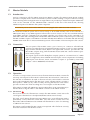
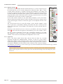
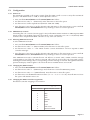
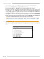
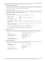
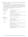
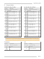
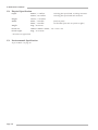
Solid State Logic
S O U N D | | V I S I O N
SUPERANALOGUE
X-RACK
Super-Analogue™ Outboard
XR622 X-Rack Master Module User’s Guide
This documentation package contains the User’s Guide for your new X-Rack Master
module. Depending on the age of your X-Rack, these pages may already be present in
your X-Rack Owner’s Manual – please check to see if these pages match your Manual.
If they do not, these pages should be filed alongside it.
Please Note. The XR622 X-Rack Master module operates in conjunction with the XR625 X-Rack Mic Amp
and XR623 X-Rack Line Return modules.
X-Rack units prior to serial number XRK0110 are compatible with the X-Rack Master module
but may require a small modification to the buscard; if the ‘SOLO’ LED is permanently
illuminated, resistors R1 and R2 will need removing. In addition, any Mic Amp or Line Return
module(s) must be fitted immediately to the left of the Master module – later X-Rack units do
not have this limitation and modules may be freely placed anywhere in the later X-Rack units.
For correct operation of this module, your X-Rack unit must be running V1.2/0 or later
software. Please refer to your X-Rack Owners Manual for instructions on how to check the
current software version and how to obtain and install a newer version if required.
There may be a newer version of the X-Rack Owner’s Manual available for download from our
website (www.solid-state-logic.com)
82S6XR0F0B
F.
F.1
Master Module
X-Rack Master Module
Introduction
Used in conjunction with the XR623 X-Rack Line Return module, the XR622 X-Rack Master module
provides a complete small scale mix and monitor system for studios seeking a compact solution for mixing
and monitoring in the analogue domain. A single X-Rack can provide up to 28 line level inputs. Additional
racks can be connected via the ‘MIX BUS LINK’ connector on the rear of the X-Rack unit, allowing
additional inputs to be added to the system if required.
X-Rack units prior to serial number XRK0110 are not equipped with a ‘MIX BUS LINK’ connector.
F.2
The X-Rack Total Recall system allows session setups to be recalled instantly and can be archived as a
MIDI SysEx dump to any MIDI sequencer. The monitor section controls can also be controlled remotely
using MIDI controller commands from any MIDI controller. Up to three racks can be connected to an
AWS 900 or AWS 900+ and integrated with the AWS 900 Total Recall system via the serial port. Connecting
the MIX and REC outputs of the XR622 to the MIX and REC Insert Returns of the AWS 900 and selecting
INSERT SUM mode allows almost unlimited expansion of the number of line level inputs to the console.
Connection
INS RTN INS SND
EXT
MIX
MON
REC
ALT MON FOL MON
The rear panel of the module carries a pair of 25-way ‘D’ connectors. The left-hand
connector provides the main and alternate Monitor outputs as well as a stereo External
Input and the Mix Bus Insert Return. The right-hand connector provides Mix and
Record Bus outputs along with the Mix Bus Insert Send and a Follow-Monitor (prelevel control) output.
All outputs (apart from the headphone output) operate at a nominal level of +4dBu
and are configured to drive standard line level inputs. Level compensation for feeding
600Ω inputs from the Bus, Insert and Monitor outputs is provided by removable
jumpers – refer to Section F.3.4 for details.
XR622
SEL
F.3
0
3
6
9
12
15
18
24
30
36
42
48
MONITOR
Operation
As well as a compact stereo monitor section, the X-Rack Master module contains the
mix amps and outputs for the X-Rack’s internal Mix, Record and Solo/AFL busses.
The Mix bus is intended to be used as the main mix bus and includes a balanced
insert point immediately before the Mix level control. The Record bus provides a
direct path to a DAW (or any other recorder), allowing the Mix bus to be used to
provide a monitor mix while recording one or more inputs via the Record bus.
If the X-Rack is fitted with XR621 Mic Amp modules these can be routed directly to
the Record bus using the ‘REC L’ and ‘REC R’ switches on the XR621 module.
F.3.1 Mix Section
1
This section carries all of the Mix bus controls; the ‘MIX LEVEL’ control allows the
overall gain of the Mix bus to be adjusted (the Record bus level is fixed).
The ‘INS’ switch brings the Mix Bus Insert Return into circuit (the Insert Send is
permanently active) whilst the ‘SUM REC’ and ‘INS SUM’ switches allow the
Record bus and Insert Return to be summed with the Mix bus to allow for summing
of additional mix sources.
The ‘MON’ switch enables the Mix output to be replaced with whichever source(s)
have been selected for the Monitor section.
MIX
1
SUM
REC
MON
MIX LEVEL
INS
INS
SUM
MONITOR
MIX
AFL
REC
SOLO
EXT
LEVEL
ALT
MONO
DIM
CUT
Page F-1
X-Rack Owner’s Manual
F.3.2 Monitor Section
2
The Monitor Section enables the Mix and Record busses or a stereo external input to
be monitored, the source to monitor being set by either the ‘MIX’, ‘REC’ or ‘EXT’
switches either separately or together, allowing great flexibility in recording and
monitoring signals. The ‘EXT’ input would normally be playback from the main
recorder or DAW. The selected monitor signals can be routed back to the Mix output
using the MON switch in the Mix Section, allowing composite mixes to be easily
recorded back to the master recorder or DAW ADC.
If one of the ‘SOLO’ switches on any other X-Rack modules is active, the ‘SOLO’
LED will illuminate and the AFL bus will be switched to the monitor output in place
of the selected signal. The level of the AFL signal can be adjusted with the ‘AFL’
control.
The overall monitor level is set by the ‘LEVEL’ control and the ‘MONO’ switch
allows quick mono compatibility checking. The ‘DIM’ and ‘CUT’ switches provide
either partial (between –3 and –30dB) or full attenuation of the monitored signal as
required.
Metering of the selected source (or sources) is provided by the stereo bargraph
meter
3
which measures the signal level immediately prior to the ‘LEVEL’ control.
Two sets of stereo loudspeaker outputs plus a headphone amplifier are provided.
The headphone socket is driven by a fixed gain amplifier immediately post the
‘LEVEL’ control and is un-affected by the loudspeaker ‘ALT’ switch.
F.3.3 Expansion
XR622
SEL
0
3
6
9
12
15
18
24
30
36
42
48
MONITOR
MIX
3
SUM
REC
MON
MIX LEVEL
INS
INS
SUM
MONITOR
MIX
AFL
REC
SOLO
EXT
LEVEL
ALT
2
MONO
DIM
CUT
Each of the three X-Rack busses (Mix, Record and Solo/AFL) are accessible
externally through the ‘MIX BUS LINK’ connector on the rear of the X-Rack.
Additional X-Racks can be connected via this connector, allowing additional inputs
to be mixed together and feed a single Master module. The pinout for this connector
is detailed in Section 5.2 of the X-Rack Owner’s Manual; if the connector listing is
not present in your manual, a more recent copy may be downloaded from the Solid State Logic website
(www.solid-state-logic.com).
Only one XR622 master module is required per system – connecting two or more X-Rack units fitted with
XR622 modules together will cause serious gain errors and distortion (though it will not damage the system
electronics).
Page F-2
X-Rack Master Module
F.4
Configuration
F.4.1 Dim Level
The attenuation applied to the monitor signal when the ‘DIM’ switch is active is set by the Total Recall
processor. The default level is –15dB, it can be adjusted as follows:
• Press and hold SETUP/MIDI until the SETUP/MIDI LED flashes.
• Use the D-Pot to select ‘d1’ (DIM Level). Press the D-Pot to select this option.
• Use the D-Pot to set the required level (between –3dB and –30dB).
• Press the D-Pot once more to set the selected value and return to the setup menu or press and hold
SETUP/MIDI until the SETUP/MIDI LED stops flashing to return to normal operation.
F.4.2 MIDI Remote Control
Controlling the ‘soft’ controls (see next page for list) on the XR622 Master module via MIDI requires MIDI
remote mode to be enabled. Optionally the X-Rack can be configured to use one or all (default) MIDI
channels and to map different MIDI controllers to any of the soft controls.
F.4.3 Selecting MIDI remote mode
To select MIDI remote mode:
• Press and hold SETUP/MIDI until the SETUP/MIDI LED flashes.
• Use the D-Pot to select ‘re’ (Remote Mode). Press the D-Pot to select this option.
• Use the D-Pot to select ‘m1’. The X-Rack monitor controls listed below will now respond to MIDI
controller messages.
• Press the D-Pot once more to set the selected value and return to the setup menu or press and hold
SETUP/MIDI until the SETUP/MIDI LED stops flashing to return to normal operation.
Once MIDI remote mode is selected the unit will behave as normal until a MIDI controller message
corresponding to one of the soft controls is received. This will lock out all of the ‘soft’ front panel controls,
retaining the current settings until a corresponding controller message is received. The right hand decimal
point in the display window lights to show that the unit is in MIDI remote active mode.
F.4.4 Changing the MIDI channel
• Press and hold SETUP/MIDI until the SETUP/MIDI LED flashes.
• Use the D-Pot to select ‘m1’ (MIDI Setup). Press the D-Pot to select the MIDI Setup menu.
• Use the D-Pot to select ‘ch’ (MIDI Channel). Press the D-Pot to select this option.
• Use the D-Pot to set the MIDI Channel to listen to (‘01’ to ‘16’ or ‘al’ for ‘all’). Press the D-Pot to leave
this option. The default value is all.
F.4.5 Changing the MIDI controller assignments
The default controller mapping is shown below:
Default MIDI Controller Mapping
MIDI Controller
1
2
3
4
5
6
7
8
9
Master Module Control
MIX
REC
EXT
ALT
MONO
DIM
CUT
AFL Level
Monitor LEVEL
Page F-3
X-Rack Owner’s Manual
Optionally MIDI controllers can be mapped onto different Master module functions. To do this:
• Press and hold SETUP/MIDI until the SETUP/MIDI LED flashes.
• Use the D-Pot to select ‘m1’ (MIDI Setup). Press the D-Pot to select the MIDI Setup menu.
• Use the D-Pot to select ‘le’ (MIDI Remote Learn) and press SAVE to enable learn mode.
• Operate any one of the ‘soft’ controls on the XR622 Master module. This will cause the LED of the
selected control to flash (the SEL LED will flash if either of the potentiometers have been chosen).
Assign a MIDI controller to the selected function by operating the required MIDI controller. Repeat the
‘operate – assign’ process for all required controls.
• Press the D-Pot again to leave this option and return to the setup menu or press and hold SETUP/MIDI
until the SETUP/MIDI LED stops flashing to return to normal operation.
• Switch assignments can be reset to the system defaults by pressing COPY/DEL when in MIDI Remote
Learn mode; the Empty LED indicating when the assignments have been deleted.
Only single controls can be mapped to a MIDI controller. Therefore, mapping an X-Rack control to a MIDI
controller which is already in use will remove the previous mapping. The original X-Rack control will require
re-mapping itself before it can be controlled again.
F.4.6 Level Compensation
Each of the Insert Send, Mix Bus, Record Bus and Monitor outputs are provided with level compensation
for driving low (600Ω) inputs. Level compensation is activated by removing a jumper for each output as
follows:
600Ω Output Level Compensation
Link
Output
LK2
Record Bus Left
LK1
LK3
LK4
LK5
LK6
LK7
LK8
Page F-4
Alt/Main Monitor Right
Record Bus Right
Alt/Main Monitor Left
Insert Send Left
Insert Send Right
Mix Bus Left
Mix Bus Right
X-Rack Master Module
F.5
Performance Specification
The following page contains audio performance specification figures for the X-Rack Master module. No
other Solid State Logic products are covered by this document and the performance of other Solid State
Logic products can not be inferred from the data contained herein.
F.5.1 Measurement Conditions
For each set of figures on the following pages, the specific unit and test setup will be stated at the
beginning of that section. Any changes to the specified setup for any particular figure(s) will be detailed
beside the figures to which that difference applies.
F.5.2 Measurement References
Unless otherwise specified the references used in this specification are as follows:
• Reference frequency:
1kHz
• Source impedance of Test Set:
50Ω
• Reference level:
• Input impedance of Test Set:
0dBu, where 0dBu ≈ 0.775V into any load
100kΩ
• All unweighted measurements are specified as 22Hz to 22kHz band limited RMS and are expressed in
units of dBu
• All distortion measurements are specified with a 36dB/Octave low pass filter at 80kHz and are
expressed as a percentage
• The onset of clipping (for headroom measurements) should be taken as 1% THD
• Unless otherwise quoted all figures have a tolerance of ±0.5dB or 5%
• All measurements are made with the operating level switch set for +4dBu
F.5.3 Mix Bus Performance
Signal applied to one channel of an X-Rack Line Input module and routed to Mix Bus. Signal measured
on Mix Output. All other inputs un-routed from the bus under test. Mix Bus Gain control set to 0dB.
Gain
Continuously variable from –∞ to 0dB
Frequency Response
±0.1dB from 20Hz to 20kHz
–3dB at 150kHz
THD + Noise
(+24dBu applied, 0dB gain)
Equivalent Input Noise
(Input terminated with 150Ω)
< 0.005% from 20Hz to 10kHz,
< 0.008% at 20kHz
< –88dBu
F.5.4 Record Bus Performance
Signal applied to one channel of an X-Rack Line Input module and routed to Record Bus. Signal measured
on Record Output. All other inputs un-routed from the bus under test.
THD + Noise
(+24dBu applied, 0dB gain)
< 0.005% from 20Hz to 20kHz
Equivalent Input Noise
(Input terminated with 150Ω)
< –88dBu
Frequency Response
±0.1dB from 20Hz to 20kHz
–3dB at 150kHz
Page F-5
X-Rack Owner’s Manual
F.6
Calibration Information
The X-Rack Master module is factory calibrated and should only need calibration if a potentiometer or
other component has been replaced or if it is suspected that there is a problem with calibration.
In each of the following instructions it is assumed that the lid of the X-Rack has been removed and that
power has been applied. It is also assumed that, unless otherwise specified, all switches are released and
all front panel potentiometers are at unity or minimum position as appropriate. The required accuracy for
each adjustment will be specified along with the target value. All level and distortion measurements
should be made with audio-band 20Hz to 20kHz filters unless otherwise specified.
All presets are accessible from the top of the unit.
F.6.1 Mix Level Tracking
Equipment Required:
Calibrated audio oscillator and audio level meter
Input and Output:
Oscillator to Insert Return Left
Output to the audio level meter from Mix Bus Output (use Left or Right
as instructed below)
Test Signal:
Unit Setup:
Adjustment:
F.6.2 Meter Level
1kHz sinewave @ +24dBu
Select ‘INS’ and set ‘MIX LEVEL’ to centre.
1. Measure Mix Bus Output Left and note the reading.
2. Connect the oscillator to Insert Return Right.
3. Measure Mix Bus Output Right and adjust VR6 (‘TRACKING’) for a level
which matches that measured in step 1.
Equipment Required:
Calibrated audio oscillator and audio level meter
Input and Output:
Oscillator to Insert Return Left
Output to the audio level meter from Follow Mon Output (use Left or
Right as instructed below)
Test Signal:
1kHz sinewave @ +24dBu
Unit Setup:
1. Select ‘INS’ and set ‘MIX LEVEL’ to maximum.
Adjustment:
1. Measure the Left ‘Follow Mon’ Output. Adjust the oscillator level to
obtain +24dBu, if necessary.
2. Select
2. Adjust VR5 (‘0dB LEFT’) so that that the top left hand ‘red’ LED on the
bargraph meter just illuminates.
3. Connect the oscillator to Insert Return Right.
4. Measure the Right ‘Follow Mon’ Output. Adjust the oscillator level to
obtain +24dBu, if necessary.
5. Adjust VR4 (‘0dB RIGHT’) so that that the top right hand ‘red’ LED on the
bargraph meter just illuminates.
Page F-6
X-Rack Master Module
F.7
Connector Details
Ins Rtn, Ext, Mon, Alt Mon
Ins Snd, Mix, Rec, Fol Mon
Conn’ Type:
Conn’ Type:
Location:
Pin
1
14
2
15
3
16
4
17
5
18
6
19
7
20
8
21
9
22
10
23
11
24
12
25
13
Rear Panel
25-pin ‘D’ Type Female
Description
Alt Monitor Out Right (+ve)
Alt Monitor Out Right (–ve)
0V
Alt Monitor Out Left (+ve)
Alt Monitor Out Left (–ve)
0V
Main Monitor Out Right (+ve)
Main Monitor Out Right (–ve)
0V
Main Monitor Out Left (+ve)
Main Monitor Out Left (–ve)
0V
External Input Right (+ve)
External Input Right (–ve)
0V
External Input Left (+ve)
External Input Left (–ve)
0V
Mix Insert Return Right (+ve)
Mix Insert Return Right (–ve)
0V
Mix Insert Return Left (+ve)
Mix Insert Return Left (–ve)
0V
n/c
Location:
Cct
8
7
6
5
4
3
2
1
Pin
1
14
2
15
3
16
4
17
5
18
6
19
7
20
8
21
9
22
10
23
11
24
12
25
13
Rear Panel
25-pin ‘D’ Type Female
Description
Follow Monitor Right (+ve)
Follow Monitor Right (–ve)
0V
Follow Monitor Left (+ve)
Follow Monitor Left (–ve)
0V
Record Output Right (+ve)
Record Output Right (–ve)
0V
Record Output Left (+ve)
Record Output Left (–ve)
0V
Mix Output Right (+ve)
Mix Output Right (–ve)
0V
Mix Output Left (+ve)
Mix Output Left (–ve)
0V
Mix Insert Send Right (+ve)
Mix Insert Send Right (–ve)
0V
Mix Insert Send Left (+ve)
Mix Insert Send Left (–ve)
0V
n/c
Cct
8
7
6
5
4
3
2
1
Please note that the ‘D’ type connector binding posts fitted to the X-Rack Master Module are 4-40 UNC thread.
Headphones
Location:
Conn’ Type:
Pin
Tip
Ring
Sleeve
Front Panel
Stereo 1/4" Jack Socket
Description
Left
0V
PL2
Location:
Conn’ Type:
Pin
n/a
Internal
16-pin IDC Plug
Description
For Future Expansion
Page F-7
X-Rack Owner’s Manual
F.8
Physical Specification
Depth:
200mm / 7.9 inches
275mm / 10.9 inches
including front panel knobs, excluding connectors
including front panel knobs and connectors
Width:
35mm / 1.4 inches
49mm / 1.9 inches
front/rear panels
overall width (front and rear panels are offset)
Height:
Weight:
Boxed size:
Boxed weight:
171mm / 6.75 inches
260g / 9.5 ounces
190mm x 290mm x 70mm / 7.5" x 11.5" x 2.5"
460g / 16.5 ounces
* All values are approximate
F.9
Environmental Specification
As per X-Rack – see page 19.
Page F-8