1
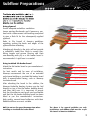
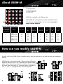
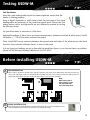
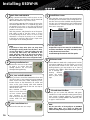
The world’s best-selling electric floor heating brand™
120 Volt USDW-M
Matting System
Installation Manual
IMPORTANT
Read this manual before attempting to install your heater.
Incorrect installation could damage the heater and will invalidate
your warranty.
TECHNICAL HELPLINES
US:1-888-927-6333
Contents
Do’s and Don’ts
Electrical Considerations
Subfloor Preparations
About USDW-M
How you can modify USDW-M
Testing USDW-M
Before Installing USDW-M
Installing USDW-M
Warranty, Exclusions and Terms and Conditions
3
4-5
6-7
8
8
9
9
10
11 - 12
Before you start
120 Volts
Double check your measurements and ensure you have the right heater sizes for the area you need to
heat. Bear in mind that the heating element should not be installed under appliances or permanent
fixtures and fittings such as refrigerators, washer-dryer, cabinets, tubs, vanity units etc. Below is a quick
reference guide:
Area (ft²)
Heaters
10
15
20
25
30
42
60
USDWM-140-120
USDWM-210-120
USDWM-280-120
USDWM-350-120
USDWM-420-120
USDWM-710-120
USDWM-840-120
If you are missing any of the box contents or believe you have the incorrect heaters to cover the area
required, please call 888-927-6333 for assistance.
There will be other materials you need to complete the project which are not included within the heating
system. These include:
• Digital ohm multimeter - For space heating cable testing.
• A 4” double gang electrical box (for the thermostat) - with a mud square.
• Tile installation products and tools.
• Scissors.
NOTE: Please ensure you do not damage the wire. Be sure to test the
system BEFORE you tile. See pg 9 for more details.
Warmup undertile heating cable for installation in floors.
If these instructions are followed, you should have no problems. However, if you require
assistance at any stage, please call our helpline at 888-927-6333.
2
Warmup Inc., the manufacturer of USDW-M, accepts no liability, expressed or implied, for any loss or consequential damage suffered as a
result of installations which in any way contravene the instructions that follow.
Do’s and Don’ts
DO
Carefully read this installation manual before
commencing installation.
Use a qualified installer.
Ensure the system is tested before, during
and after installation.
Sketch a diagram of the wire layout for future
reference, which should be kept with the
manual for future reference.
DON’T
Plan your USDW-M layout and installation so
that any drilling after tiling (e.g. for installing
cabinets, threshold strips) will not damage
the space heating cables.
Install USDW-M under any floor other than
ceramic, quarry or natural stone tiles.
Check USDW-M is working immediately before commencing tiling.
Commence installation on a concrete floor
that has not been fully cured.
Take particular care when tiling not to dislodge or damage the space heating cable.
Leave surplus matting rolled up under units
or fixtures - use the right size.
Wear gloves to prevent irritation from the
fibre glass mesh.
Install USDW-M on stairs, up walls or in a
closet.
If you remove the wire from the mesh for a
custom layout, maintain a min. 2” max. 4”
spacing between the heating cable.
Run the floor sensor wire or power lead over
or under the space heating cable..
Make sure that ALL space heating cable. is
positioned under the tiles in the installation.
Protect the space heating cable with cardboard or hardboard between installation and
tiling.
Use thin set mortars and grouts suitable for
use with underfloor heating, as specified in
the manufacturers’ instructions.
Ensure that each tile is solidly bedded in tile
adhesive, with no gaps or voids beneath.
Remember to install the floor probe for the
Warmup (register mark) thermostat.
Make sure all electrical work is done by qualified persons in accordance with local building
and electrical codes, the National Electrical
Code (NEC), especially article 424,
Part V of the NEC, ANSI/NFPA70.
Ensure that you have electrical provision to
run the heating system at 120Vac.
Remember to attach the rating labels
included within this manual to your breaker
box and controls.
Connect two USDW-Ms in series, only connect
mats in parallel.
Shorten the space heating cable. at any time.
Allow the space heating cable to cross over or
touch each other at any point.
Allow strips of mesh to overlap.
Store tiles, sharp or heavy objects on any of
the wiring while tiling or bang a trowel on
the wired area to remove excess mortar from
the trowel.
Switch on the installed heating system until
the adhesive has fully cured (1-3 weeks
minimum).
Attempt to repair the space heating cable
if it becomes damaged. Call the technical
helpline for further instruction: 888-WARMFEET/888-927-6333.
Install the space heating cable under any
built-in items (i.e. tubs, vanity units, bookshelves, walls or partitions), or under any
zero-clearance, dedicated-location furniture
or appliances.
Install on a concrete slab.
3
Electrical Considerations
For each Warmup®Heater you install, you will have an unheated lead running from the floor to the thermostat’s electric
connection. The joint connecting the unheated lead to the space heating cable must be at least 2 inches from the wall
and in a position to be covered by tile and thin set mortar.
We recommend you do not alter the length of the unheated lead, however if necessary, the wire can be extended if a
UL-approved wire and connector box suitable for the purpose is used (e.g. waterproof if going into the floor, etc). This
must be carried out by a qualified electrician in accordance with local/state laws and guidelines. If the unheated lead
is shortened, a minimum of 12” of lead must be left before the joint.
It may be necessary to chisel out short channels in the subfloor to minimize the increased height presented by the
floor probe and the unheated lead provided.
Separate conduit will be required to run the unheated lead and the sensor wire back up to the thermostat. Please note
that they cannot be placed within the same conduit. Neither the unheated lead or sensor wire must cross, or come
into contact with, the space heating cable. Bear in mind that you will need to make provision for drawing the unheated
leads and sensor wire up through the conduit up to the control box.
Making Electrical Provision
Please refer to the table on page 8 to calculate the amperage load for your particular system. For smaller areas,
you may be able to utilize an existing circuit. In most cases, however, you will need a separate circuit to power
the Warmup heaters.
The Warmup thermostat has a maximum resistive load of 16 amps. It also includes a built-in GFCI. If you want to
control more than 16 amps worth of heating via a single thermostat you will need to use Warmup’s master / relay
configuration. Instead of using the thermostat, a different model of master thermostat is used to control individual
switching units (each capable of switching up to a 16 amp load, and each containing its own GFCI). The relay units
require their own separate electrical feed, and up to 10 relay units can be daisy chained to a single master unit via low
voltage cabling. For further information please call the Warmup Helpline or visit www.warmup.com.
The thermostat should be connected to the main electrical supply via a fuse or circuit in accordance with the National
Electrical Code. If the thermostat used does not include a built-in Ground Fault Circuit Interrupter (GFCI), then one
must be added to the circuit between the main power supply and the thermostat. If the thermostat does include a
GFCI, it is NOT recommended to include another in the circuit, as this may cause accidental tripping of the control unit.
Ensuring Safety
Install the Warmup thermostat within the same room as the heater. In order to ensure the efficient running of the
system within bathrooms, we recommend that the controls are located at least 36 inches away from shower openings
or basin back splash areas so that you minimize the possibility of exposure to water.
The rating label in this manual must be attached to the circuit breaker box for referral by the homeowner or electrical
inspector. An additional smaller label, also in this manual, is to be attached adjacent to or on the thermostatic control.
Floor probe location
The floor probe wire for the Warmup thermostat will be approximately 15 feet long. The end of the wire contains a
capped sensor that should be centered between two heater wires at least 12” into the heated area. At no time should
the probe wire cross the space heating cable.
As with all electrical projects, we strongly recommend that you should not undertake electrical work unless you are competent to do so. Do make
sure all electrical work is done by qualified persons in accordance with local building and electrical codes, the National Electrical Code (NEC),
especially article 424, Part V of the NEC, ANSI/NFPA 70.
All work must conform to current National and local codes. Always follow the instructions and if in any doubt consult a qualified electrician.
4
Electrical Considerations
Max. 16 amps
5
Subfloor Preparations
To fully utilize the long-term durability of ceramic tiling, whether heated or not, it is important that the
design, construction and preparation of the subfloor is carried out correctly.
It is essential that the sub-floor be sufficiently rigid to support the ultimate weight that it will have to
bear without movement or deflection.
The choice of products for subfloor preparation and tile will vary depending on the existing subfloor,
preferred tiling system and choice of tile. This document is only intended to be an outline guide to laying ceramic floor tiles. Further help regarding floor preparation and tile application is available from the
tile adhesive manufacturers and or the Tile Council of America (TCA) Tel: 864-646-8453, website: www.
tileusa.com. Alternatively, you may wish to seek professional advice e.g. an architect or contractor.
Subfloor Preparation
Prior to heater installation, it is important that the subfloor is properly prepared as per Tile Council of
America Guidelines.
WOOD SUBFLOOR: Boards need to be of suitable material or requires backer board. Chipboard and O.S.B.
boards (flake boards) are not suitable bases for ceramic floor tiling.
SUBFLOOR PREVIOUSLY COVERED IN LINOLEUM, CORK OR CARPETING: All old flooring and adhesive must
be removed. If bitumen is present as adhesive residues it must be removed. If the bitumen is a damp
proofing membrane or isolation membrane it must be covered with a minimum 2” of sand/cement self
leveler, taking care not to puncture the bitumen coating. If using other damp proofing or tanking systems, contact the manufacturer for advice.
We strongly recommend installing tile and stone flooring according to manufacturer’s recommendations, TCA guidelines and ANSI
specifications.
Special Precautions
MOSAIC TILE AND PORCELAIN: When installing mosaic tile and CERTAIN PORCELAIN, we recommend a twostep process. Cover the space heating cable with latex self-leveling compound before tiling to ensure a
flat, smooth surface, then thin set the mosaic according to typical practice.
EXPANSION JOINTS: Do not install the space heating cable through an expansion joint. Install the space
heating cable right up to the joint, if necessary, but do not bridge the joint.
INSULATION: Do not install rigid insulation directly above or below backer board or mortar.
If possible, install insulation as shown in diagrams.
Insulation dramatically enhances the performance and efficiency of floor warming systems.
6
Subfloor Preparations
Using plywood
Ensure adequate underfloor ventilation.
Secure existing floorboards and if necessary, prelevel with a latex cement self-levelling compound
to give a flush fit for the subsequently applied
plywood.
Refer to Tile Council of America guidelines
regarding sealing the backs and edges of the
plywood before attaching.
Carrelage ou pierre*
Mortier-colle ou adhésif
Maille chauffante Warmup
Contreplaqué de 19mm (3/4”) ou
panneau isolant
Sous-plancher en bois
Attaching ply directly to the joists will not provide
a sufficiently stable floor finish to accept tiles;
fitting tongue and groove flooring and then
over-boarding with ply or a tile backer board is
recommended. A rigid base is essential.
Using insulated tile backer board
Attach the tile backer board as per manufacturer’s
instructions.
For best results and for ease of installation,
Warmup recommends the use of an extruded
polystyrene building or insulated tile backer board
with a cement-based facing, such as Warmup
Insulation Board.
After attaching the board to the subfloor, the
Warmup Undertile Heating System may be laid
directly on top of the tile backer building board,
and then tiled over. It is important to ensure
that the tile adhesive and grout used are flexible
and that the tile backer building board has been
fitted as per the manufacturer’s instructions.
High quality, cement-based adhesives with their
flexible additives are most suitable.
NOTE: Do not use the green Warmup primer when
installing on insulated tile backer board.
Carrelage ou pierre*
Mortier-colle ou adhésif
Maille chauffante Warmup
Panneau isolant Warmup
(recommandé)
Mortier-colle ou adhésif
Sous-plancher en béton
The above is for general guideline use only.
Installations and subfloor work must be as per
Tile Council of America Guidelines.
7
About USDW-M
A - Heating element
B - Space heating cable
C - Factory-made joint
D - Power lead
USDW-M is available in 6 different sizes
Each USDW-M is designed to produce a specific amount
of heat based on its length. For this reason you must
never shorten USDW-M.
120 Volt Matting Heater Guide
# of heating mats
per 16A supply
point @120V
Heaters
Wire colors
Wattage
(W)
Nominal wire
length (ft)
Nominal Amps
Resistive (A)
Resistance
(Ω)
Mat Length
(ft)
Mat Width
(ft)
13
USDWM-140-120
blue
140
41
1.2
100.1
6’0”
1’8”
8
USDWM-210-120
silver
210
56
1.8
67.8
9’3”
1’8”
6
USDWM-280-120
grey
280
85
2.3
51.6
12’3”
1’8”
5
4
2
USDWM-350-120
USDWM-420-120
USDWM-710-120
red
red
350
420
710
134
114
2.9
3.5
5.9
40.9
34.6
20.3
15’3”
18’3”
25’8”
1’8”
1’8”
1’8”
2
USDWM-840-120
black/grey
840
243
7.1
17.0
36’6”
1’8”
NOTE: The Warmup thermostat can switch up to 16 amps. If you are installing more than two heaters you will require a junction box.
NOTE: The mesh size may vary between +/- 5% due to manufacturing tolerances.
How can you modify USDW-M
In order to fit your USDW-M into a specific area, it may be necessary to cut and turn the mat (examples
below).
NEVER cut the space heating cable. When cutting and flipping
USDW-M take care not to cut or damage the space heating
cable. Never allow strips of mesh to overlap. If you remove
the wire from the mesh for a custom layout, maintain a
min. 2”, max. 4” spacing between the heating cable.
8
Testing USDW-M
Test the Heater
Once the space heating cable layout has been completed, ensure that the
heater is working properly.
Using a digital ohmmeter or multi-meter, check the resistance of the space
heating cable and continuity of the protective ground braid. Please note that
analog meters with a moving needle are not sufficiently accurate for testing
the Warmup heater.
Set your Ohm meter to measure in 0-200 Ohms.
Acceptable readings of these ohms resistance measurements (between the black & white wires) should
fall within +/- 15% of the values indicated on page 8.
There should NOT be any continuity between the ground wire and either of the white wire or the black
live wire. Any continuity indicates there is a short in the circuit.
If at any time your readings are not in line with the guidelines above, or you suspect there is a problem,
please call the Warmup Technical Helpline at 888-927-6333.
Before installing USDW-M
A
Check USDW-M size
Please take a moment to double-check that your plan has the proper room dimensions and that you have the
correct size and proper number of USDW-Ms. Once USDW-M has been cut it cannot be returned. Mats should run
backwards and forwards between walls and obstructions as shown in the examples.
NOTE:
When laying two or
more heaters, ensure
the unheated leads
reach the thermostat.
B
Before Installation Test
Perform the first test following the steps described above to ensure that USDW-M has not
been damaged during transport. Do not wire to a plug at this stage.
9
Installing USDW-M
1
Mark Floor and USDW-M
Using a permanent marker, mark out areas on the
subfloor where units and fixtures will be fitted. DO
NOT install USDW-M in any of these areas.
5
Start by laying USDW-M in the location closest to the
thermostat (DO NOT affix or cut USDW-M yet). Mark
the position of any turns or cuts that you will need
to make to the loose wire on USDW-M and mark the
positions on the floor.
Install Floor Sensor
Place the floor sensor (from the thermostat) below
the fibreglass mesh between two heating elements.
The floor sensor must be installed centrally between
the two runs of heating element and should extend
a minimum of 12” into the heated area. Secure the
floor sensor using tape.
Min 12”
Mark the positions and planned route of the power
lead cables as well as the floor sensor. It is best
to avoid placing the floor sensor in areas of heat
fluctuations. It may be necessary to cut a channel
in the floor to ensure the floor sensor is kept at the
same height as the heating element.
NOTE:
If you have a loose wire (wire cut away from
the fibreglass mesh) make sure the loose wires
are no closer than 2” from each other, the wall
or from any other wires still attached to the
mesh. All joints need to be placed on the floor
beneath the tiles. No cables may cross at any
time (including the floor sensor and power lead).
2
3
During Installation Test
10
Install Warmup Thermostat and floor probe.
6
Perform the same test as described
on page 9 to ensure that the
heating element has not been
damaged during planning.
Cut, turn and affix USDW-M
When you have ensured that USDW-M has been laid
correctly in Step 2, start cutting and turning USDW-M
where marks have been made, beginning at the
location closest to the thermostat. Be careful and
never cut the space heating cable. Affix USDW-M
with the double sided tape on the mat. Use tape to
affix the loose wires.
Once USDW-M is fitted,
check to ensure there are
no loose sections paying
close attention to the
ends of the mats and any
section which has been
turned.
4
Test the probe wire:
Temperature sensor wire must be verified before
and after installation. For probe resistance, refer
to the thermostat instructions.
After Installation Test
Perform the same test as in step 2.
7
Fit Power Leads
Each USDW-M is fitted with a single power lead for
connecting USDW-M to the thermostat. To ensure
the power lead remains at the same level as the
heating element, you may need to cut or chisel a
channel in the subfloor. When doing this take care
not to damage the
heating
element.
Secure the power
lead in place using
tape.
Tile and Grout the floor
Ensure you use ceramic tile adhesives and grouts
suitable for use with undertile heating systems (they
must contain a flexible adhesive). It is important
that each tile is solidly bedded in tile adhesive, with
no gaps or voids beneath.
NOTE:
Do not store tiles or heavy objects on USDW-M
while tiling. Wait for 8 days to allow the
adhesive to dry before you switch on the system.
Warranty
WARMUP 30-YEAR WARRANTY
Models:
USDW heaters and USDW-M heaters sold by Warmup, Inc.
THE WARMUP 30-YEAR WARRANTY DOES NOT EXTEND TO THERMOSTATS, WHICH ARE COVERED BY A ONE-YEAR GUARANTEE FROM THE DATE OF ORIGINAL PURCHASE.
GOVERNING LAW: unless otherwise governed by applicable state law, this warranty shall be interpreted and enforced in accordance with the laws of the State
of Connecticut.
This 30-Year Warranty applies:
1. Only to the original homeowner(s) from the date of purchase
2. Only if the unit is registered with Warmup within thirty (30) days after purchase. Filling out the card accompanying this warranty in its entirety will
complete registration. In the event of a claim, proof of purchase is required, i.e. invoice and receipt. Such invoice and receipt should state the exact
model that was purchased; and
3. Only for the duration of the Lifetime of the floor covering under which it was originally installed if the purchaser of the heater remains the owner of the
residence in which it was installed. If the original purchaser sells such residence, the warranty will transfer and continue for the duration of the 30 years
from date of purchase.
4. Only if the heater has been grounded and protected by a GROUND FAULT CIRCUIT INTERRUPTOR (GFCI) at all times.
COVERAGE
1. The warranty period begins on the date of purchase. Registration is effective only when a letter of confirmation is sent by Warmup, Inc.
2. Warmup’s Undertile Heater is guaranteed by WARMUP, INC. (“Warmup”) to be free from defects in materials and workmanship under normal use and
maintenance for thirty (30) years, provided the Product is installed in accordance with the accompanying Warmup installation manual, any special written
design or installation guidelines by Warmup, Inc. for a particular project, the National Electrical Code (NEC), the Canadian Electrical Code (CED), and all
applicable local building and electrical codes; and
3. Provided Warmup heaters are installed under ceramic tile, marble and natural stone surfaces.
4. During the period of Warranty, Warmup will arrange for the heater to be repaired or (at its discretion) have parts replaced free of charge. The costs of
repair or replacements are your only remedy under this Warranty. Such cost does not extend to any cost other than direct cost of repair or replacement
by Warmup and does not extend to costs of relaying, replacing or repairing any floor covering or floor.
5. If Warmup, Inc. determines the repair of the product is not feasible; we will replace the product with equal or similar features and functionality at
Warmup’s sole discretion. WARMUP’S MAXIMUM LIABILITY IS LIMITED TO THE ORIGINAL PURCHASE PRICE OF THE HEATER MULTIPLIED BY THE PERCENTAGE OF
THE WARRANTY PERIOD REMAINING.
EXCLUSIONS
Warmup, Inc. shall in no event be liable for incidental or consequential damages, including but not limited to extra utility expenses or damages to property.
This Warranty is null and void if
1. The floor covering over the heater(s) is damaged, lifted, replaced, repaired or covered with subsequent layers of flooring.
2. The heater fails due to damage caused during installation or tiling, unless damage is caused directly by an employee of Warmup. It is therefore essential
to check that the heater is working (as specified in the installation manual) prior to tiling.
3. Damage as a result of floods, fires, winds, lightning, accidents, corrosive atmosphere or other conditions beyond the control of Warmup, Inc.
4. Use of components or accessories not compatible with Warmup heaters
5. Warmup products installed outside the United States.
6. Parts not supplied or designated by Warmup, Inc.
7. Damage or repair required as a result of any improper use, maintenance, operation or servicing.
8. Failure to start due to interruption and/or inadequate electrical service
9. Any damage caused by frozen or broken water pipes in the event of equipment failure.
10. Changes in the appearance of the product that does not affect its performance.
11. The owner, or his/her designated representative, attempts to repair the product without receiving prior authorization from Warmup. Upon notification
of a repair problem, Warmup, Inc. will issue an Authorization to Proceed under the terms of this Warranty.
If Warmup is required to inspect or repair any defects caused by any exclusions referenced above, all work will be fully chargeable at Warmup’s inspection
and repair rates then in effect.
WARMUP, INC. DISCLAIMS ANY WARRANTY NOT PROVIDED HEREIN, INCLUDING ANY IMPLIED WARRANTY OF THE MERCHANTABLE OR IMPLIED WARRANTY OF FITNESS
FOR A PARTICULAR PURPOSE. WARMUP, INC. FURTHER DISCLAIMS ANY RESPONSIBILITY FOR SPECIAL, INDIRECT, SECONDARY, INCIDENTAL, OR CONSEQUENTIAL
DAMAGES ARISING FROM OWNERSHIP OR USE OF THIS PRODUCT, INCLUDING INCONVENIENCE OR LOSS OF USE. THERE ARE NO WARRANTIES THAT EXTEND BEYOND
THE FACE OF THIS DOCUMENT. NO AGENT OR REPRESENTATIVE OF WARMUP, INC. HAS ANY AUTHORITY TO EXTEND OR MODIFY THIS WARRANTY UNLESS SUCH
EXTENSION OR MODIFICATION IS MADE IN WRITING BY A CORPORATE OFFICER.
DUE TO DIFFERENCES IN BUILDING AND FLOOR INSULATION, CLIMATE AND FLOOR COVERINGS, WARMUP, INC. MAKES NO REPRESENTATION THAT THE FLOOR
TEMPERATURE WILL ACHIEVE ANY PARTICULAR TEMPERATURE OR TEMPERATURE RISE. UL STANDARD LISTING REQUIREMENTS LIMIT THE HEAT OUTPUT OF WARMUP
UNDERTILE HEATING, AS SUCH, USERS MAY OR MAY NOT BE SATISFIED WITH THE FLOOR WARMTH THAT IS PRODUCED. WARMUP DOES WARRANT THAT ALL HEATERS
WILL PRODUCE THE RATED WATT OUTPUT LISTED ON THE HEATER NAMEPLATE, WHEN OPERATED AT THE RATED VOLTAGE.
TERMS AND CONDITIONS
Shipping Discrepancies:
Incoming materials should be inventoried for completeness and for possible shipping damage. Any visible damages or shortages must be noted prior to
accepting the material. Any discrepancy concerning type or quantity of material shipped, must be brought to the attention of your Warmup® reseller within
15 days of the shipping date entered on the packing slip for the order.
Miscellaneous:
The terms of this Limited Warranty are exclusive and supercede any other warranty or terms and conditions relating to the subject matter whether included
in a purchase order for this product or in any other document or statement.
If you have any questions before, during or after your installation
do not hesitate to call the Warmup Technical Helpline on
888-927-6333
Complete and submit the warranty form online
at www.warmup.com!
Warmup Inc.
52 Federal Road
Unit 1F
Danbury, CT 06810
Helpline / Assistance: 1-888-927-6333
Fax: 1-888-927-4721
www.warmup.com
[email protected]
V. 12.11