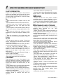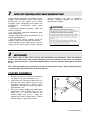
1
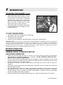
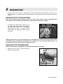
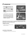
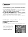
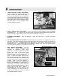
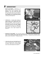
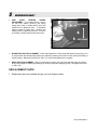
ASSEMBLY INSTRUCTIONS
OPERATOR’S MANUAL
PARTS LIST
Walk-Behind
Mower
32” cut model
Actual product may differ slightly from product pictured above
Models covered:
SGV13320KW
GVTP SM32-R0303.1
This page intentionally blank
GVTP SM32-R0303.1
1
preliminaries
Congratulations!
You have just purchased one of the finest pieces of outdoor power equipment on the market today. If properly
cared for, your new mower will provide years of dependable service. Please read and follow this instruction
manual carefully in order to get the most out of your new equipment.
As you carefully uncrate your unit, you will find the following items:
1 Mower Unit
1 Caster Kit Box including:
2 - Caster arms
2 - Caster horns with mounted wheels and spacers
1 Fuel Tank assembly complete with cap
1 Handle Bar Kit including:
1 – Handle assembly with mounted brake and safety levers
1 – Safety instruction display bracket
1 – Deflector chute
1 – Transmission shift lever assembly
2 – Upper brake rods
1 – Package of assembly hardware
1 – Package containing operating manuals and warranty registration
Each product leaves our factory in excellent condition; occasionally, however, some damage may occur during
shipment. If any such damage is found upon initial inspection, immediately notify the transport carrier who
delivered your machine, as they are solely responsible for such damage, as well as any subsequent
adjustments necessary.
Before assembly, please take a moment and record your model number and serial number below for
future reference (both numbers are located on the silver tag adhered to the rear of the engine deck):
Model number_______________________________
Serial number________________________________
Also be sure to promptly fill out and return the warranty registration enclosed in your manual packet.
Your new mower requires very little assembly. Simply follow the instructions contained within this manual to
begin enjoying the benefits of your new unit.
CALIFORNIA PROPOSITION 65 WARNING
Gasoline and Diesel engine exhaust and some of its constituents are known to the State of California to cause cancer, birth defects and
other reproductive harm.
As an owner of off-road gasoline or diesel engine equipment and/or as an employer, you also may have an obligation under the
California Occupational Safety and Health Act or under Proposition 65 to warn persons exposed to gas and diesel engine exhaust
and/or other Proposition 65 chemicals in and around your workplace. See California Health and Safety Code section 25249.5, Title 22 of
the California Code of Regulations at Section 1200 er seq., and Title 8 of the California Code of Regulations Section 5194.
R0303.1
GVTP SM32-R0303.1
2
safety rules regarding outdoor power equipment
PLEASE READ THE FOLLOWING BEFORE ASSEMBLING OR OPERATING UNIT
TRAINING
• Read, understand, and follow all instructions in the
manual and on the unit before starting. If the
operator(s) or mechanic(s) can not read English it is
the owner’s responsibility to explain this material to
them.
• Become familiar with the safe operation of the
equipment, operator controls, and safety signs.
• All operators and mechanics should be trained.
The owner is responsible for training the users.
• Only allow responsible adults, who are familiar
with the instructions, to operate the unit.
• Never let children or untrained people operate or
service the equipment. Local regulations may
restrict the age of the operator.
• The owner/user can prevent and is responsible for
accidents or injuries occurring to themselves, other
people or property.
PREPARATION
• Evaluate the terrain to determine what
accessories and attachments are needed to
properly and safely perform the job. Use only
accessories and attachments approved by the
manufacturer.
• Wear appropriate clothing including safety shoes,
safety glasses and ear protection. Long hair, loose
clothing or jewelry may get tangled in moving parts.
• Inspect the area where the equipment is to be
used and remove all objects such as rocks, toys
and wire, which can be thrown by the machine.
• Use extra care when handling gasoline and other
fuels. They are flammable and vapors are
explosive.
a) Use only an approved container.
b) Never remove fuel cap or add fuel with the
engine running. Allow engine to cool before
refueling. Do not smoke.
c) Never refuel or drain the machine indoors.
• Check that operator’s presence controls, safety
switches and shields are attached and functioning
properly. Do not operate unless they are functioning
properly.
OPERATION
• Never run an engine in an enclosed area.
• Mow only in the daylight or with good artificial
light, keeping away from holes and hidden hazards.
• Be sure transmission is in neutral and cutting
blades are disengaged before starting engine.
• Be sure of your footing while using pedestrian
controlled equipment, especially when backing up.
Walk, don’t run.
• Do not mow in reverse unless absolutely
necessary. Always look down and behind before
and while traveling in reverse.
• Be aware of the mower discharge direction and do
not point it at anyone. Do not operate the mower
without either the entire grass catcher or the
deflector in place.
• Slow down and use caution when making turns
and when changing directions on slopes.
• Never raise deck with the blades running.
• Never leave a running unit unattended. Always
disengage cutting blades, set transmission in
neutral, stop engine, and remove keys before
leaving unit. Keep hands and feet away from the
cutting units.
• Disengage the cutting blades when not mowing.
• Never operate with guards not securely in place.
Be sure all safety features are attached, adjusted
properly and functioning properly.
• Never operate with the discharge deflector raised,
removed or altered, unless using a grass catcher.
• Do not change the engine governor setting or over
speed the engine.
• Stop on level ground, disengage cutting blades,
set transmission in neutral, shut off engine before
leaving the operator’s position for any reason
including emptying the grass catchers or
unclogging the chute.
• Stop equipment and inspect blades after striking
objects or abnormal vibration occurs. Make
necessary repairs before resuming operations.
• Keep hands and feet away from the cutting units.
• Never carry passengers and keep pets and
bystanders away.
• Do not operate the unit while under the influence
of alcohol or drugs.
• Slow down and use caution when making turns
and crossing roads and sidewalks. Stop blades if
not mowing.
• Use care when loading or unloading the machine
into a trailer or truck.
• Use care when approaching blind corners, shrubs,
trees or other objects that may obscure vision.
GVTP SM32-R0303.1
2
safety rules regarding outdoor power equipment (cont.)
SLOPE OPERATION
Slopes are a major factor related to loss-of-control
and tip-over accidents, which can result in severe
injury or death. All slopes require extra caution. If
you cannot back up the slope, or if you feel uneasy
on it, do not drive on it.
Do
• Mow across the face of slopes; never up and
down.
• Remove obstacles such as rocks, tree limbs, etc.
• Watch for holes, ruts, or bumps. Uneven terrain
could overturn the unit. Tall grass can hide
obstacles.
• Use slow speed. Choose a slow speed so that you
will not have to stop or change speed while on the
slope.
• Use extra care with grass catchers or other
attachments. These can change the stability of the
unit.
• Keep all movement on the slopes slow and
gradual. Do not make sudden changes in speed or
direction.
Do Not
• Do not start or stop on a slope. If tires lose
traction, disengage the blade and proceed slowly
straight down the slope.
• Do not turn on slopes unless necessary, and then,
turn slowly and gradually downhill, if possible.
• Do not mow near drop-offs, ditches, or
embankments. The operator could lose footing or
balance or mower could suddenly turn over if a
wheel is over the edge of a cliff or ditch, or if an
edge caves in.
• Do not mow on wet grass. Reduced footing or
traction could cause sliding.
• Do not mow excessively steep slopes.
• Do not use grass catcher on steep slopes.
CHILDREN
Tragic accidents can occur if the operator is not
alert to the presence of children. Children are often
attracted to the unit and the mowing activity. Never
assume that children will remain where you last
saw them.
• Keep children out of the mowing area and under
the watchful care of another responsible adult.
• Be alert and turn unit off if children enter the area.
• Before and during reverse operation, look behind
and down for small children.
• Never carry children. They may fall off and be
seriously injured or interfere with safe unit
operation.
• Never allow children to operate the unit.
• Use extra care when approaching blind corners,
shrubs, trees, or other objects that may obscure
vision.
EMISSIONS
• Engine exhaust from this product contains
chemicals known, in certain quantities, to cause
cancer, birth defects, or other reproductive harm.
• Look for the relevant Emissions Durability Period
and Air Index information on the engine emissions
label.
MAINTENANCE AND STORAGE
• Always observe safe refueling and fuel handling
practices
when
refueling
the
unit
after
transportation or storage.
• Always follow the engine manual instructions for
storage preparations before storing the unit for both
short and long term periods.
• Always follow the engine manual instructions for
proper start-up procedures when returning the unit
to service.
• Never store the machine or fuel container inside
where there is an open flame, such as in a water
heater. Allow unit to cool before storing.
• Shut off fuel while storing or transporting. Do not
store fuel near flames or drain indoors.
• Keep all hardware, especially blade attachment
bolts, tight and keep all parts in good working
condition. Replace all worn or damaged decals.
• Never tamper with safety devices. Check their
proper operation regularly.
• Clean grass and debris from cutting units, drives,
mufflers, and engine to prevent fires. Clean up oil or
fuel spillage.
• Stop and inspect the equipment if you strike an
object. Repair, if necessary, before restarting.
• Never make adjustments or repairs with the
engine running unless specified otherwise.
• Park machine on level ground. Never allow
untrained personnel to service machine.
• Use jack stands to support components when
required.
• Carefully release pressure from components with
stored energy. (e.g. springs)
• Use care when checking blades. Wrap the
blade(s) or wear gloves, and use caution when
servicing them. Only replace blades. Never
straighten or weld them.
• Keep hands and feet away from moving parts.
GVTP SM32-R0303.1
2
safety rules regarding outdoor power equipment (cont.)
• Grass catcher components are subject to wear,
damage, and deterioration, which could expose
moving parts or allow objects to be thrown.
Frequently check components and replace with
manufacturer’s
recommended
parts,
when
necessary.
• Check brake operation frequently. Adjust and
service as required.
• Use only factory authorized replacement parts
when making repairs.
• Always comply with factory specifications on all
settings and adjustments.
• Only authorized service locations should be
utilized for major service and repair requirements.
• Never attempt to make major repairs on this unit
unless you have been properly trained. Improper
3
service procedures can result in hazardous
operation, equipment damage and voiding of
manufacturer’s warranty.
unit assembly
Note: Please refer to Parts List for correct part identification and placement. Parts list reference
numbers are called out by sheet number followed by reference number(s) on that sheet: (1:1) indicates
Sheet 1, reference number 1; (2:32,34-38) indicates Sheet 2, reference numbers 32 through 38 excluding
33; etc.
Note: Some assembly steps may already have been completed at the factory. Simply disregard factorycompleted steps and proceed to the next assembly step.
CASTER ASSEMBLY
•
•
•
Remove Lynch pin (1:16) and all but the bottom
1/4” spacer (1:15) from Caster horn (1:13).
Slide Caster horn up through Caster arm (1:8),
securing with same spacers and lynch pin
removed in previous step. NOTE: When
assembled in this manner, cutting height will be
approximately 2-1/2".
With front of mower propped up, install caster
assemblies to front of Blade Deck (1:1) with
twelve 3/8" x 1" bolts, flat washers, and
serrated flange nuts (1:9-11).
(Bolts are
installed from inside of mower deck.) Tighten
all bolts securely. Lower front of mower.
GVTP SM32-R0303.1
3
unit assembly (cont.)
DISCHARGE DEFLECTOR ASSEMBLY
•
Attach discharge deflector (1:5) using two 5/16"
x ¾" bolts and lock nuts (1:6-7). CAUTION:
Do not over tighten lock nuts.
TRANSMISSION SHIFT LEVER ASSEMBLY
•
Install Shift indicator panel (2:45) onto rear of
engine deck (2:1) with two 5/16 x 3/4” hex bolts
(2:47), securing with large serrated flange nuts
(2:48). Leave hardware finger tight.
•
Remove 3/8” nylon lock nut and flat washer
(2:43,44) from shift stud atop transmission
(2:14 – location ‘A’).
Remove 1/2 x 2-1/2” hex bolt, three oillite
washers, and lock nut (2:40-42) from top rear of
engine deck.
•
•
Insert same 1/2” bolt down through top forward
hole in Shift lever (2:38), slip same three
washers up onto threads of bolt, then drop bolt
into same hole.
GVTP SM32-R0303.1
3
unit assembly (cont.)
TRANSMISSION SHIFT LEVER ASSEMBLY (cont.)
•
•
•
Position ‘double-D’ hole in bottom leg of shift
lever onto transmission stud, then slowly move
handle of shifter back and forth until hole drops
onto matching base of stud.
Replace washer and nut onto transmission
stud. Tighten securely. Replace lock nut onto
1/2” bolt. Tighten snugly while allowing for
shifter movement.
Work shift lever through gear range, adjusting
indicator panel for display alignment, then
tighten indicator panel hardware.
FUEL TANK ASSEMBLY
•
•
•
•
•
Install fuel tank mount brackets (2:57, 58) onto
engine deck using four 5/16 x ¾” hex bolts and
serrated flange nuts (2:59-60). Do not tighten.
Place rubber pads (2:61) on top of mount
brackets, making sure to not block fuel tank tab
slots.
Place fuel tank (2:65) on top of slotted rubber
pads, making sure tabs on bottom of tank drop
through slots in tank brackets.
Slip fuel tank straps (2:62) around ends of tank,
making sure bottom of straps slip under top
ends of mounting brackets. Secure each strap
with one 1/4-20 x 1-1/2” hex bolt and serrated
flange nut (2:63-64). Tighten both straps and
mounting bracket hardware securely.
Slip end of fuel line from engine fully onto
barbed nipple of fuel elbow (located under
tank), securing with supplied spring clamp.
GVTP SM32-R0303.1
3
unit assembly (cont.)
HANDLE ASSEMBLY INSTALLATION
•
Install handle assembly (4:1) to upper portion of
engine deck using four 1/2" x 1-1/4" hex bolts
and serrated flange nuts (4:3-4). Adjust for
comfortable operation, then tighten securely.
•
Locate wiring harness and route harness down
the right side of handle assembly. Attach
harness terminals to engine, transmission and
blade clutch using the wiring diagram at the
back of this manual as a guide. Attach harness
to right handle bar with two plastic tie wraps.
•
Route throttle and choke cables (4:22, 22b –
attached to handlebar) down left side of handle
assembly. Attach each cable to left side of
mower handle using metal cable clip. Also
install cable routing clip (4:34) onto engine deck
– see Sheet 4 of Parts list for location.
•
Connect throttle and choke cables to throttle
body on lower front of engine – see
Throttle/Choke Cable Adjustment in the
Maintenance section of this manual for details.
•
Also attach the safety instruction display
bracket (4:30) to the front of the mower dash
with two 5/16-18 x 3/4” hex bolts and serrated
flange nuts (4:31-32).
•
Install "L" shaped end of upper brake rod (4:9),
from outside, through brake handle (4:5) and
brake lock handle (4:10). Secure with fender
washer and bridge pin (4:14-15).
Attach
adjustable rod fitting end (3:41) on lower end of
rod to side idler plate (3:21) using flat washer
and bridge pin (3:42-43). Repeat for other side.
IMPORTANT: Adjust upper rods for handle
comfort and proper drive belt release; also
adjust lower brake rods (3:14), by means of
5/16” wing nut (3:20) so that brakes will hold
firmly when brake lock handle is engaged.
Attach safety
bracket here
Your mower is now ready to be started and checked for proper operation. Some minor
final adjustments may be required; see the Maintenance portion of this manual.
GVTP SM32-R0303.1
4
unit operation
STARTING THE ENGINE
IMPORTANT NOTE: The procedures outlined within this section are general guidelines, and are in no way
meant to replace or supercede engine manufacturer’s operating instructions. In order to obtain optimum
performance from your engine, refer to your engine manual.
BEFORE STARTING ENGINE:
•
Be sure that the unit is completely assembled, all fasteners are tightened securely, and all safety guards
and components are in place.
• Be sure to check engine’s oil and gasoline*. (See engine manual for recommended oil and gasoline
specifications.) Never check the engine while it is running or while you are smoking. Check only when
engine is cold.
* All machines are shipped without oil or gasoline unless otherwise noted.
• Be sure that in-line fuel valve is set to open
position.
CLOSED
OPEN
TO START ENGINE:
•
Set throttle control fully up to “Choke” position.
If your engine has an auxiliary choke, pull the
choke knob fully out to engage.
•
Turn ignition key to ‘run’ position.
GVTP SM32-R0303.1
4
unit operation (cont.)
STARTING THE ENGINE (cont.)
•
•
Grasp recoil handle and pull briskly. You may
have to pull several times before engine starts.
(If engine fails to start within a reasonable
amount of time, discontinue and check engine
manual for further instructions.) Note: Do not
allow recoil rope to snap back into recoil;
damage to the rope or recoil could result.
After engine starts, move throttle control down
to approximately half and disengage choke by
pushing knob fully in.
PULL
BRISKLY
TO SHUT ENGINE DOWN:
•
•
•
•
Allow engine to idle for 2-3 minutes before shutting down.
Set throttle control to ‘slow’ position.
Turn ignition key to ‘off’ position.
If engine is not to be started for a prolonged period, turn fuel valve to closed position.
IMPORTANT NOTE: If you experience problems with your engine that cannot be satisfactorily resolved by following the
instructions contained within the engine manual, contact your local engine dealer, or call the toll-free service number listed in
the repair section of the engine manual. All engine service, warranty or otherwise, is required to be performed by a
manufacturer-authorized service center. The equipment manufacturer is neither authorized nor responsible for any type of
warranty engine service, nor is it equipped to perform any such service.
MOWER OPERATION
GENERAL RULES TO OBSERVE BEFORE
AND DURING OPERATION:
•
•
•
•
•
•
Inspect your unit before each and every use. Check for worn, bent or broken components, loose fasteners,
low or flat tires, etc., and repair or replace prior to operation. DO NOT OPERATE A DEFECTIVE UNIT –
SERIOUS INJURY OR DEATH CAN RESULT.
Clear the entire work area of all debris that could cause damage to or become entangled in the unit. Rocks
and large branches can wedge themselves between the blades and deck, causing engine seizure, blade
damage, or personal injury. If in doubt, remove it.
Do not start unit until you are ready to begin mowing, and promptly shut off unit as soon as operation is
complete.
Keep hands, feet and clothing away from rotating parts. Never place your feet or hands under mower deck
when the engine is running.
Use proper discretion in selecting your debris removal pattern, especially on uneven terrain. Avoid steep
hills, especially if surface is wet. Do not travel straight down slopes exceeding 14 degrees. If tires begin to
slip when climbing a slope, the grade is too steep for safe operation. Angle the unit to a less steep slope
until tires stop slipping and traction is regained.
Be keenly aware of your surroundings while operating unit – children and pets can pop out of nowhere.
GVTP SM32-R0303.1
4
•
unit operation (cont.)
Learn to listen to your machine – being aware of what a well-running unit sounds like can alert you to a
potential problem. A straining engine or clanging blades or a slapping belt mean that trouble is almost sure
to follow.
ENGAGING THE CUTTING BLADES:
Note: Never engage the mower blades until you are ready to mow and be certain to disengage them
when finished. Never attempt any adjustment or repairs when the blades are engaged.
•
To engage the cutting blades, simply pull out
the blade engage switch knob (4:29), located in
the center of the handle dash. To disengage,
simply push the knob in. Always be sure
cutting blades are disengaged before stopping
the mower.
PULL – ENGAGE
PUSH – DISENGAGE
Important safety note: Power to the engine will be immediately cut if both of the safety handles (Parts
List Ref #4:18) are released while cutting blades are engaged. This is an important safety feature – do
not attempt to defeat it. Serious injury or death may result.
ENGAGING THE TRANSMISSION:
Note: Never attempt any adjustment or repairs with the transmission engaged.
•
Always start your mower in neutral with brake
handles in locked position.
2
LOCKING BRAKES
1
GVTP SM32-R0303.1
4
•
•
•
unit operation (cont.)
Move the shift lever to first gear (‘1’), unlock
brakes, and slowly release the brake handles.
Your mower has five forward speeds (‘1’ – ‘5’);
simply slide the shifter lever to the appropriate
indicator position to select that gear. The
machine can be shifted on the run. NOTE: If
climbing a hill, the brake squeeze handles
might have to be momentarily activated.
CAUTION: The shift lever should never be left
or held in drive position for an extended time
when the brake squeeze handles are in the
locked position.
To engage transmission in reverse, slide shifter
lever into neutral (‘N’), lock both left and right
brake thumb locks, lift up on reverse lockout
bar (2:51) and slide shifter lever into reverse
(‘R’); unlock thumb locks and slowly release
brake levers. NOTE: Machine will reverse
towards operator. Use caution while using
this feature. If control is lost, release grip
on handles – see note below.
Important safety note: Power to the engine will be immediately cut if both of the safety handles (Parts
List Ref #4:18) are released while transmission is engaged. This is an important safety feature – do not
attempt to defeat it. Serious injury or death may result.
STEERING THE UNIT:
•
Squeezing either brake handle will turn the
machine in that direction.
squeeze to turn left
squeeze to turn right
ADJUSTING CUTTING HEIGHT:
•
See Adjustments in the Maintenance section of this manual.
GVTP SM32-R0303.1
5
maintenance
GENERAL:
•
Follow implicitly the engine manufacturer’s recommendations for maintenance.
•
Always keep your machine clean - especially the engine deck. Check all adjustments periodically. Also,
periodically check that all fasteners are secure. Remember, sharp blades cut better. Always have an extra
set on hand. After re-sharpening blades, be certain they are checked for balance. Do not use blades out of
balance. Before doing any of these, check your safety and assembly instructions.
•
Never make any adjustments to the unit until the engine is off and the spark plug wire is disconnected.
•
If carburetor adjustment is necessary, stand to one side and keep feet and hands in the clear while making
adjustments.
•
Keep engine free of accumulations of grass, leaves or excessive grease.
combustible materials may result in a fire.
•
Store gasoline in a safe and approved container in a cool, dry place.
•
Keep the unit and any fuel containers in locked storage to prevent children from playing and/or tampering
with them.
•
Do not store gasoline powered equipment or fuel containers in a basement or any closed area where
heating or heat appliances or open pilot lights are present, unless the fuel is completely drained from the
power equipment and the fuel containers.
An accumulation of these
LUBRICATION:
•
Your mower is equipped with numerous greaseable assemblies to ensure long life and minimal wear. It is
imperative that the owner address these areas. All fittings should be lubricated using a high-performance,
automotive quality grease. See maintenance schedule below.
*LUBRICATION CHART
Qty
2
2
2
2
All
Location
Caster Wheel Pivots
Caster Wheel Bearings
Mower Spindle Bearings
Drive Wheel Bearings
Pivot Points
Daily
X
X
Weekly
X
X
X
In addition all linkage points and threaded adjustments should be oiled on a weekly schedule.
*NOTE: This maintenance is necessary to keep your warranty in effect.
GVTP SM32-R0303.1
5
maintenance (cont.)
TROUBLESHOOTING:
•
UNIT WILL NOT START: Check to make sure cutting blades are disengaged. Check to make sure
transmission is in neutral. Check fuel and oil levels. Check to make sure throttle control engages engine
choke when set to ‘start’ position; adjust if needed. Check all electrical connections for positive contact;
repair or replace as necessary. If condition persists, contact dealer.
•
UNIT STALLS WHEN CUTTING BLADES ENGAGED: Make sure safety handles are depressed when
engaging blades. Check under handle dash to be sure safety rod depresses plunger on safety switch;
adjust as necessary – see Safety Switch Rod Adjustment. Check all electrical connections for positive
contact; repair or replace as necessary. If condition persists, contact dealer.
•
UNIT STALLS WHEN TRANSMISSION ENGAGED: Make sure safety handles are depressed when
engaging transmission. Check under handle dash to be sure safety rod depresses plunger on safety
switch; adjust as necessary – see Safety Switch Rod Adjustment. Check all electrical connections for
positive contact; repair or replace as necessary. If condition persists, contact dealer.
•
BLADE CUT POOR: Replace blade.
positioning when replacing blade.
•
BLADE BELT SLIPPING.: See Blade Belt Adjustment.
•
BLADE BELT VIBRATION: See Blade Belt Adjustment or Blade Deck Pulley Alignment.
•
DRIVE BELTS SLIPPING: Check spring tension on each drive idler – spring at factory is 8-1/4” oal
extended length. If adjustment is needed, see Side Idler Tension Spring Adjustment. If tension is correct,
check brake band adjustment. Then check upper and lower brake rod adjustment.
•
DRIVE BELTS ROLL OFF IN REVERSE: See Drive Pulley Alignment.
Note: See Cutting Blade Height Adjustment for proper spacer
ADJUSTMENTS:
Note: Before making any adjustments or repairs, place the shift lever in the neutral position and the lock
brakes. Stop engine and disconnect spark plug wire.
•
HANDLE HEIGHT ADJUSTMENT: Handle
height adjustment is achieved by loosening the
four 1/2” bolts securing the handle assembly to
the upper portion of the engine deck and raising
or lowering the handle assembly for the
greatest comfort. Be certain both sides are
adjusted the same. After adjustment is made,
the upper and lower brake rods may have to be
readjusted as well. See brake adjustment.
LOWER
RAISE
GVTP SM32-R0303.1
5
•
maintenance (cont.)
THROTTLE/CHOKE CABLE ADJUSTMENT:
Correct throttle cable adjustment allows for full
range of motion on engine throttle body in
conjunction with throttle control on handle dash.
Correct choke cable adjustment engages choke
when choke knob is pulled fully out. To adjust
either cable, loosen cable clip screw on engine,
then slide cable in or out. Retighten screw,
recheck, readjust as needed.
CHOKED
SLOW
CHOKE
CABLE
FAST
THROTTLE SCREW
CABLE
•
SAFETY SWITCH ROD ADJUSTMENT: Loosen set screws on safety handles, raise each handle
approximately 1/4 – 1/2”, retighten one set screw, check for uniform contact between both handles with
handle assembly, retighten other set screw. Note: tighten set screws to 150 in. lbs.
•
STEERING ADJUSTMENT:
adjustment.
•
CUTTING BLADE HEIGHT ADJUSTMENT: Each blade assembly contains six 1/4” blade spacers: three on
the bottom of the spindle assembly between blade and spindle, and three above between the spindle and
the blade bolt jam nut. Combined with the axle adjustment set at the factory, cutting height is set at
approximately 2-1/2”. Cutting blade height can be adjusted to between 1-3/4” and 3-1/4” by removing jam
nut and repositioning washers. Retighten jam nut to 60 ft. lbs.
•
AXLE HEIGHT ADJUSTMENT:
Your unit
comes with a unique rapid-adjust axle
assembly for additional cutting height
adjustment. Initial factory adjustment sets the
bottom rear edge of the blade deck
approximately 1-1/2” above the mowing
surface; however, it can be adjusted to 5” in
height. To adjust, first position a jack under the
rear of engine deck and raise. Loosen the two
3/8” bolts on either side of axle assembly (held
in place by press-fit nuts, so only one wrench is
needed). Drop or raise axle assembly to
provide desired height, then retighten bolts.
Remove jack and adjust the front casters by
repositioning the spacers. Note: Remember
that factory-set cutting blade height is 1” above
bottom edge of blade deck.
Note: It is
recommended that the front height of the
mower be adjusted to 1/4” lower than the rear,
to allow for the blades to cut with the leading
edge and thus assure a finer cut.
Check tire pressure – 20psi rear, 50psi front.
If correct, see Brake
3/8” BOLTS
ADJUST
GVTP SM32-R0303.1
5
•
maintenance (cont.)
BRAKE ADJUSTMENT: LOWER ROD - The
brake assembly has been set at the factory.
However, they may periodically need
adjustment. As a rule of thumb, the bottom
bend of the lower brake rod (3:14) should be
3/8” lower than the center of the pivot boss hole
in the brake arm (3:5). If adjustment is needed,
simply thread the 5/16 wing nut (3:20) in or out
to obtain specified adjustment.
ADJUST
•
UPPER ROD - To adjust brake handles for
comfortable grip, remove bridge pin and fender
washer securing top of upper brake rod to
brake lever assembly. Slide end of rod out of
brake handle, turn rod in or out of rod fitting end
replace rod into brake handle, check, readjust
as needed; when set to desired position,
replace washer and bridge pin. NOTE: After
adjustment, be sure mower stops completely
and uniformly when brake handles are
squeezed.
•
BLADE BELT ADJUSTMENT: We recommend checking belt tension after one hour and then after the
next 10 hours of operation, then re-check after each 50 hours of use. To check tension, first engage cutting
blades. Place a belt tensioning gauge in the center of the belt span. The gauge should read 10 pounds
pressure with a 3/8" deflection. To adjust belt tension:
INCREASE
•
Loosen the outer nut of the doubled nut set
(1:44) securing tensioning rod, then tighten or
loosen nut to adjust tension. Recheck, readjust
as needed. Tighten inner nut securely against
outer nut when final adjustment is achieved.
DECREASE
CHECK TENSION HERE
GVTP SM32-R0303.1
5
•
maintenance (cont.)
SIDE
IDLER
TENSION
SPRING
ADJUSTMENT: To increase tension, remove
nut and lock washer securing rear spring
hanger bolt (3:34) in middle tension hole, and
replace bolt in uppermost hole. To decrease
tension, replace in lowest hole. Replace lock
washer and nut, tightening securely. If tension
is still slack, replace springs and/or drive belts.
INCREASE
DECREASE
•
BLADE DECK PULLEY ALIGNMENT: Check initial alignment of each pulley with blade clutch pulley (2:13)
on engine shaft with straight edge; adjust as needed by loosening set screws in each pulley and raising or
lowering pulley. Retighten set screws to 150 in. lbs. when final adjustment is complete.
•
DRIVE PULLEY ALIGNMENT: Check to see that drive pulleys are in line with side idler pulley and wheel
drive pulley; adjust as needed by loosening set screw in pulley and realigning pulley. Retighten set screws
to 150 in. lbs.
REPLACEMENT PARTS:
•
Replacement parts are available through your local Snapper dealer.
GVTP SM32-R0303.1
47
46
See Engine & Trans Group
To Blade Pulley See Engine & Trans Group
45
32" Cut Mower
BLADE DECK GROUP
SHEET 1 OF 4
R0303.1
4
28
34
33
25
31
27 32
38
37
36
31
22
5
30
35
43
40
41
7
39
42
3
thru A
44
16
29
A
15
6
14
2
9
10
8
12
1
26
12
15
11
20
21
13
25
17
18
24
19
23
GVTP SM32-R0303.1
Snapper 32” Cut Mower
R0303.1
SHEET 1 - BLADE DECK GROUP
REF #
PART #
QTY
1
--------2
--3
4
5
----6
7
8
--9
10
11
12
13
14
15
--16
17
18
19
20
21
22
23
24
25
26
27
--28
29
30
31
32
33
3010260
3079166
3079090
3079088
3079091
3031895
3031100
3031033
3031987
3027499
3079090
3079088
3031031
3031436
3033118
3031437
3031033
3031034
3031987
3031306
3033117
3031441
3031442
3031588
3031305
3033115
3033116
3031571
3036300
3031033
3031987
3031892
3021584
3031309
3031170
3036145
3031439
3031893
3031357
3036313
3031224
3023241
3031043
1
1
2
1
1
2
4
6
6
1
1
1
2
2
2
2
12
12
12
4
2
10
4
2
2
2
2
2
2
8
8
2
2
12
2
2
4
2
1
1
2
1
1
DESCRIPTION
Blade deck
Decal – ‘Operating Rules 1-8’
Decal – ‘Danger – Keep Hands & Feet Away’
Decal – ‘Danger – Flying Material’
Decal – ‘Caution-Rotating Parts’
Rubber hood strap (w/attaching hardware)
3/16 pop rivet (attaches strap receiving cup to hood)
3/8-16 x 1" hex bolt
3/8-16 small serrated flange nut
Discharge deflector
Decal – ‘Danger – Keep Hands & Feet Away’
Decal – ‘Danger – Flying Material’
5/16-18 x 3/4" hex bolt
5/16-18 lock nut
Caster arm
Grease fitting – 3/16” push-in
3/8-16 x 1" hex bolt
3/8" flat washer
3/8-16 small serrated flange nut
1" flange bushing
Caster horn
Caster height spacer – 1/2”
Caster height spacer – 1/4”
Caster spacer set (complete 1 side)
Lynch pin
9-3.50 x 4 wheel & tire assy
5/8-11 x 5" hex bolt
5/8-11 jam lock nut
Spindle assy
3/8-16 x 1" hex bolt
3/8-16 small serrated flange nut
5/8-11 x 9-1/2" hex bolt
16" lo-lift blade
1/4" spacer
Spindle shaft key – 1/4” x 1”
Blade belt pulley
5/16-18 x 1/4” socket set screw
5/8-11 jam nut
3/8-16 x 2-1/2” hex bolt
Deck idler arm pivot boss
3/4" sleeve bushing
Deck idler arm
1/2" flat washer
GVTP SM32-R0303.1
34
3031987
1
3/8-16 small serrated flange nut
Snapper 32” Cut Mower
R0303.1
SHEET 1 - BLADE DECK GROUP (cont.)
REF #
PART #
QTY
35
36
37
38
39
40
41
42
43
44
45
46
----------47
3031410
3031686
3036120
3032132
3031402
3031008
3031568
3031568
3036226
3031987
3036206
3027415
3031917
3046580
3075436
3079090
3079088
3031900
1
1
1
1
1
1
1
1
1
2
1
1
1
1
1
1
1
2
DESCRIPTION
3/8-16 x 2" carriage bolt
3/4" spacer bushing
Deck idler pulley
3/8-16 large serrated flange nut
3/8" ball joint - right hand thread
3/8 lock washer
3/8-24 jam nut
3/8-24 jam nut
Deck idler tension rod
3/8-16 small serrated flange nut
Blade belt
Deck hood
Mower hood edge trim – 27” length
Decal – ‘Snapper Pro’
Decal – ‘32” ‘
Decal – ‘Danger – Keep Hands & Feet Away’
Decal – ‘Danger – Flying Material’
2” rubber hood cap
GVTP SM32-R0303.1
66
62
63
39
40
65
61
64
38
43
60
5
41
15
53
to A
46
45
54
55
51
52
50
49
14 29
28
48
59
42
27
6
4
A
3
2
2
28 27
1
29
N
30
47
57
R
58
31
44
21
56
33
34
35
32
31
16
36
18
17
37
1
7
22
23
24
25
26
8
9
19
20
To Drive Wheel See Side Idler &
Axle Group
5
4
3
10
11
12
To Ref #8 this sheet
32" Cut Mower
13
To Blade Pulleys See Blade Deck Group
ENGINE & TRANS GROUP
SHEET 2 OF 4
R0303.1
GVTP SM32-R0303.1
Snapper 32” Cut Mower
SHEET 2 - ENGINE & TRANS GROUP
R0303.1
REF #
PART #
QTY
1
----2
3
4
5
6
7
8
9
10
11
12
13
14
15
16
17
18
--19
20
21
22
23
24
25
26
27
--28
29
30
31
32
33
34
35
36
--37
38
39
40
3010261
3027503
3031573
3039121
3031006
3031027
3027273
3031986
3031665
3036143
3036222
3036325
3031409
3031319
3031414
3033229
3037088
3031660
3031314
3036142
3031439
3031423
3036140
3031388
3031034
3025155
3036141
3031027
3031355
3036301
3031419
3031302
3031309
3036321
3031107
3036153
3031635
3032129
3036320
3036154
3031439
3036155
3023264
3031722
3031461
1
1
2
1
4
1
1
4
1
1
1
1
1
1
1
1
1
4
1
1
1
1
1
1
1
2
1
1
1
2
2
2
2
1
2
2
4
4
1
2
2
2
1
1
1
DESCRIPTION (no model designation denotes common)
Engine base
Blade cam cover plate
#10 x 1/2” sheet metal screw
Engine - 13hp Kawasaki w/5 amp coil
5/16-18 x 1-1/2” hex bolt
5/16 flat washer
Blade clutch anti-torque pin
5/16-18 small serrated flange nut
Engine shaft key - 1/4" x 1-7/8"
Engine-to-trans pulley
1/4" spacer
Electric blade clutch
7/16" heavy duty washer
7/16" lock washer
7/16-20 x 2 socket head cap screw
Transmission
Transmission ball switch
5/16-18 x 3/4" ‘F’ thread bolt
#9 woodruff key
Transmission pulley
5/16-18 x 1/4” socket set screw
5/8" snap ring
Transmission belt
Trans idler bolt
3/8" flat washer
5/16" SAE washer
Trans idler pulley
5/16" flat washer
3/8-16 lock nut
Trans axle coupler
Grease fitting – 1/4-28 threaded
5/8" locking collar
1/4” spacer
Trans axle - right
#9 woodruff key
5/8" bearing unit
1/4-20 x 5/8" hex bolt
1/4-20 serrated flange nut
Trans axle - left
2-V drive pulley
5/16-18 x 1/4” socket set screw
2-V drive belt
Shift lever
Handle grip - 1/4" x 1-1/4" x 4-1/2"
1/2-13 x 2-1/2" hex bolt
GVTP SM32-R0303.1
Snapper 32” Cut Mower
SHEET 2 - ENGINE & TRANS GROUP (cont.)
R0303.1
REF #
PART #
QTY
41
42
43
44
45
46
47
48
49
50
51
52
53
54
55
56
57
58
59
60
61
62
63
64
65
66
-----------
3023182
3031637
3031915
3031034
3027412
3079096
3031031
3031986
3027429
3027420
3027421
3031031
3031436
3031032
3031027
3031986
3027484
3027485
3031031
3031986
3032151
3034923
3031292
3032129
3044639
-----3031755
3016325
3031755
3034095
3044640
3
1
1
1
1
1
2
2
1
1
1
1
1
2
2
2
1
1
4
4
2
2
2
2
1
1
1
1
1
4
1
DESCRIPTION
1/2" oillite washer
1/2-13 nylon lock nut
3/8-24 nylon lock nut
3/8" flat washer
Shift panel
Shift decal
5/16-18 x 3/4" hex bolt
5/16-18 small serrated flange nut
Manual blade engagement hole cover plate
Reverse lockout bracket
Reverse lockout bar
5/16-18 x 3/4” hex bolt
5/16-18 lock nut
5/16-18 x 1" hex bolt
5/16 flat washer
5/16-18 small serrated flange nut
Fuel tank mount – left
Fuel tank mount – right
5/16-18 x 3/4" hex bolt
5/16-18 small serrated flange nut
Slotted rubber fuel tank pad
Fuel tank strap
1/4-20 x 1-1/2” hex bolt
1/4-20 serrated flange nut
Fuel tank
Fuel cap
1/4" rubber fuel line - 12" length
In-line fuel shut-off valve
1/4" rubber fuel line - 4" length
1/2" spring clamp
Decal – ‘Snapper’ (applied to front of fuel tank)
GVTP SM32-R0303.1
See Engine & Trans Group
See Handle Group
38
43
30
31
40
42
33
21
39
36 37
41
35
37
A
34
35
22
29
23
24
25
32
27
28
26
20
19
thru
A
17
18
14
16
15
5
1
9
10
6
7
8
12
2
3
4
11
13
32" Cut Mower
SIDE IDLER & AXLE GROUP
SHEET 3 OF 4
R0303.1
GVTP SM32-R0303.1
Snapper 32” Cut Mower
R0303.1
SHEET 3 - SIDE IDLER & AXLE GROUP
REF #
PART #
QTY
1
2
--3
4
5
----6
7
8
9
10
11
12
13
14
15
16
17
18
19
20
21
----22
23
24
25
26
27
28
29
--30
31
32
33
34
35
36
37
3033231
3027407
3027408
3031008
3031033
3023152
3023151
3031613
3031423
3023153
3023154
3031426
3031425
3031427
3033218
3031583
3023150
3031027
3031382
3031910
3031027
3031382
3031896
3023255
3023256
3031613
3031467
3031417
3036156
3031911
3031406
3031860
3031406
3027405
3027406
3031033
3032132
3031862
3031406
3031112
3031987
3031088
3031986
1
1
1
4
4
1
1
2
2
2
2
2
4
2
2
2
2
2
2
2
2
2
2
1
1
2
2
2
2
2
2
2
2
1
1
4
4
2
2
2
4
2
4
DESCRIPTION
Axle assembly
Brake pivot plate - left
Brake pivot plate - right
3/8" lock washer
3/8-16 x 1 hex bolt
Brake arm - left
Brake arm - right
Grease fitting – 1/4” push-in
5/8" retaining washer
Brake link plate w/pins
Brake link plate - no pins
3/8" push-on washer
5/16" push-on washer
Brake band
13-5.00 x 6 wheel & tire assy (w/pulleys & brake drum)
1" locking collar
Lower brake rod
5/16 flat washer
#2 bridge pin
Rod fitting end - unthreaded
5/16 flat washer
#2 bridge pin
5/16-18 wing nut w/nylon insert
Side idler plate - left
Side idler plate - right
Grease fitting – 1/4” push-in
1/2-13 x 3-1/2" hex bolt
1/2" id x 5/8" spacer
Side idler pulley
1/2" id x 3/8" spacer
1/2-13 lock nut
Side idler tension spring
1/2-13 lock nut
Side idler spring bracket - left
Side idler spring bracket - right
3/8-16 x 1 hex bolt
3/8-16 large serrated flange nut
5/8 x 4-1/4" shoulder bolt
1/2-13 lock nut
3/8-16 x 1-1/2" hex bolt
3/8-16 small serrated flange nut
5/16-18 x 3" hex bolt
5/16-18 small serrated flange nut
GVTP SM32-R0303.1
Snapper 32” Cut Mower
R0303.1
SHEET 3 - SIDE IDLER & AXLE GROUP (cont.)
REF #
PART #
QTY
38
--39
40
44
45
46
3027511
3027512
3031031
3031986
3031383
3031027
3031382
1
1
2
2
2
2
2
DESCRIPTION
Wheel drive pulley cover – left
Wheel drive pulley cover – right
5/16-18 x 3/4” hex bolt
5/16-18 small serrated flange nut
Rod fitting end (trunion)
5/16 flat washer
#2 bridge pin
GVTP SM32-R0303.1
AK
15
13
IND
28
INDAK
10
27
31
12
29
26
32
14
23
30
24
2
21
25
20
11
8
17
16
18
19
1
5
22a
6
7
22
Cable goes thru #34 this page
3
9
33
4
35
34
36
See Side Idler & Axle Group
See Engine & Trans Group
32" Cut Mower
HANDLE GROUP
SHEET 4 OF 4
R0303.1
GVTP SM32-R0303.1
Snapper 32” Cut Mower
R0303.1
SHEET 4 - HANDLE GROUP
REF #
PART #
QTY
1
--2
3
4
5
6
7
8
9
10
--11
12
13
14
15
16
17
18
----19
20
21
22
22a
22b
--23
--24
25
--26
27
28
29
30
--31
32
33
3023511
3032136
3031283
3031122
3032130
3023259
3031379
3031710
3031098
3023131
3023184
3023130
3031292
3031579
3031098
3031890
3031381
3023512
3031693
3023167
3023166
3031439
3031480
3031100
3031585
3035020
3032140
3035021
3079253
3031100
3031007
3031584
3032011
3031808
3031806
3031581
3039108
3032137
3027504
3075601
3031031
3031986
3032148
1
1
2
4
4
2
2
2
2
2
1
1
2
2
2
2
2
1
2
1
1
2
1
2
1
1
1
1
1
2
2
1
1
1
1
1
1
1
1
1
2
2
1
DESCRIPTION
Handle assembly
Mower dash overlay decal
Handle grip - 1"dia x 4-1/2"
1/2-13 x 1-1/4" hex bolt
1/2-13 serrated flange nut
Brake handle
Handle grip - 1/4" x 3/4" x 4"
1/4-20 x 2" hex bolt
1/4-20 lock nut
Upper brake rod
Brake lock - left
Brake lock - right
1/4-20 x 1-1/2" hex bolt
1/4" spring washer
1/4-20 lock nut
5/16" fender washer
#1 bridge pin
Safety switch rod
3/8" id flange bushing
Safety handle - left
Safety handle - right
5/16-18 x 1/4” socket set screw
Handle safety switch
3/16 pop rivet
Safety switch spring
Throttle control
Snap bushing - .500 id
Auxiliary choke cable (not shown)
Decal – ‘Pull for Choke’ (applied to mower dash overlay)
Pop rivet (attaches throttle to handle dash)
Throttle cable clip (fastens cable to handlebar)
Throttle T-handle
Off switch
3” jumper wire – 1/4” female to 1/4” ring – Off switch ground
5/8” star washer
5/8-18 jam nut
Key set (set of 2)
PTO switch
Safety instruction decal bracket
Safety instruction decal
5/16-18 x 3/4” hex bolt
5/16-18 small serrated flange nut
Wiring harness
GVTP SM32-R0303.1
Snapper 32” Cut Mower
R0303.1
SHEET 4 - HANDLE GROUP
REF #
PART #
QTY
------------34
35
36
3031916
3031864
3032149
3031635
3031806
3032129
3032012
3031635
3032129
1
2
1
1
1
1
1
1
1
DESCRIPTION
5” jumper wire – 1/4” female spade to bullet terminal – engine kill
8" wire tie (secures harness to handlebar)
Multi-lead ground wire – to PTO switch, safety switch & off switch
1/4-20 x 5/8” hex bolt (secures multi-lead ground to under handle dash)
1/4" star washer
1/4-20 serrated flange nut
Cable clip (holds throttle and choke cable routings in place)
1/4-20 x 5/8” hex bolt
1/4-20 serrated flange nut
ALL SPECIFICATIONS SUBJECT TO CHANGE WITHOUT NOTICE
GVTP SM32-R0303.1
2-terminal housing PTO switch - locations 'G" & 'H'
1/4" female PTO switch - location 'B'
1/4" female 'off' switch
1/4" female safety switch
PTO switch
(looking up
from below)
A
B C
D
E F
G H
A - Not used
B - To 1/4" Female on Harness
C - To Ground lead
D-F - Not Used
G-H - To 2-terminal housing on Harness
2-terminal female housing Transmission Ball Switch
1/4" female engine hot
1/4" male
1/4" female
Bullet terminal engine kill
32" Cut Mower
HARNESS WIRING SCHEME
2-terminal male housing Blade Clutch
GVTP SM32-R0303.1
McDonough, GA 30253 U.S.A.
GVTP SM32-R0303.1