1
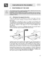
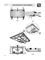
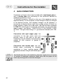
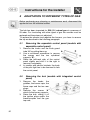
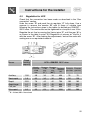
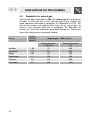
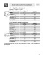
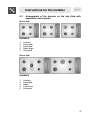
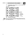
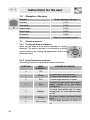
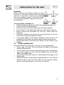
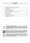
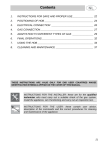
Contents
1
INSTRUCTIONS FOR SAFE AND PROPER USE ____________________ 25
2
POSITIONING OF THE HOB ____________________________________ 27
3
ELECTRICAL CONNECTION ____________________________________ 29
4
GAS CONNECTION ___________________________________________ 30
5
ADAPTATION TO DIFFERENT TYPES OF GAS _____________________ 32
6
FINAL OPERATIONS __________________________________________ 36
7
USING THE HOB______________________________________________ 39
8
CLEANING AND MAINTENANCE_________________________________ 42
THESE INSTRUCTIONS ARE VALID ONLY FOR END USER COUNTRIES
WHOSE IDENTIFICATION SYMBOLS APPEAR ON THE COVER OF THIS
MANUAL.
INSTRUCTIONS FOR THE INSTALLER: these are for the qualified
technician who must carry out a suitable check of the gas system, install
the appliance, set it functioning and carry out an inspection test.
INSTRUCTIONS FOR THE USER: these contain user advice,
description of the commands and the correct procedures for cleaning
and maintenance of the appliance.
24
Introduction
1
INSTRUCTIONS FOR SAFE AND PROPER USE
THIS MANUAL IS AN INTEGRAL PART OF THE APPLIANCE AND
THEREFORE MUST BE KEPT IN ITS ENTIRETY AND IN AN
ACCESSIBLE PLACE FOR THE WHOLE WORKING LIFE OF THE
COOKING HOB. WE ADVISE READING THIS MANUAL AND ALL THE
INSTRUCTIONS THEREIN BEFORE USING THE COOKING HOB.
ALSO KEEP THE SERIES OF NOZZLES SUPPLIED. INSTALLATION
MUST BE CARRIED OUT BY QUALIFIED PERSONNEL IN
ACCORDANCE WITH THE REGULATIONS IN FORCE. THIS
APPLIANCE IS INTENDED FOR DOMESTIC USES AND CONFORMS
TO CURRENT REGULATIONS IN FORCE. THE APPLIANCE HAS
BEEN BUILT TO CARRY OUT THE FOLLOWING FUNCTIONS:
COOKING AND HEATING-UP OF FOOD. ALL OTHER USES ARE
CONSIDERED IMPROPER. THE MANUFACTURER DECLINES ALL
RESPONSIBILITY FOR IMPROPER USE.
DO NOT LEAVE THE PACKING IN THE HOME ENVIRONMENT.
SEPARATE THE VARIOUS WASTE MATERIALS AND TAKE THEM TO
THE NEAREST SPECIAL GARBAGE COLLECTION CENTRE.
IT IS OBLIGATORY FOR THE ELECTRICAL SYSTEM TO BE
GROUNDED ACCORDING TO THE METHODS REQUIRED BY
SAFETY RULES.
THE PLUG TO BE CONNECTED TO THE POWER CABLE AND THE
SOCKET MUST BE THE SAME TYPE AND MUST CONFORM TO
CURRENT REGULATIONS.
NEVER UNPLUG BY PULLING ON THE CABLE.
IMMEDIATELY AFTER INSTALLATION CARRY OUT A BRIEF
INSPECTION TEST OF THE COOKING HOB, FOLLOWING THE
INSTRUCTIONS BELOW. SHOULD THE APPLIANCE NOT FUNCTION,
DISCONNECT IT FROM THE SUPPLY AND CALL THE NEAREST
TECHNICAL ASSISTANCE CENTRE.
NEVER ATTEMPT TO REPAIR THE APPLIANCE.
ALWAYS CHECK THAT THE CONTROL KNOBS ARE IN THE
POSITION "ZERO" (OFF) WHEN YOU FINISH USING THE HOB.
25
Introduction
THE IDENTIFICATION PLATE, WITH TECHNICAL DATA, SERIAL
NUMBER AND MARKING IS CLEARLY VISIBLE UNDER THE CASING.
THE PLATE ON THE CASING MUST NOT BE REMOVED.
BEFORE CONNECTING THE DEVICE, MAKE SURE THAT IT HAS
BEEN REGULATED FOR THE TYPE OF GAS THAT WILL FEED IT,
CHECKING THE LABEL UNDER THE HOB.
DO NOT PUT PANS WITHOUT PERFECTLY SMOOTH AND FLAT
BOTTOMS ON THE COOKING HOB GRIDS.
DO NOT USE PANS OR GRIDDLE PLATES THAT EXTEND BEYOND
THE EXTERNAL PERIMETER OF THE HOB.
THE HOB IS TO BE USED BY ADULTS ONLY. DO NOT LET
UNSUPERVISED CHILDREN PLAY WITH THE HOB.
THIS APPLIANCE IS MARKED ACCORDING TO THE EUROPEAN
DIRECTIVE 2002/96/EC ON WASTE ELECTRICAL AND ELECTRONIC
EQUIPMENT (WEEE).
THIS GUIDELINE IS THE FRAME OF A EUROPEAN-WIDE VALIDITY
OF RETURN AND RECYCLING ON WASTE ELECTRICAL AND
ELECTRONIC EQUIPMENT.
The manufacturer declines all responsibility for damage to persons or
things caused by non-observance of the above prescriptions or by
interference with any part of the appliance or by the use of non-original
spares.
26
Instructions for the installer
2
POSITIONING OF THE HOB
The following operation requires building and/or carpentry work so must
be carried out by a competent tradesman.
Installation can be carried out on various materials such as masonry,
metal, solid wood or plastic laminated wood as long as they are heat
resistant (T 90°C).
2.1
Attachment to support structure
Create an opening with the dimensions shown in the figure in the top
surface of the counter, keeping a minimum distance of 50 mm from the
rear border.
This appliance is classified as “type Y” in relation to fire hazards and
can therefore be mounted against walls higher than the work surface on
condition that a certain distance “X” be kept between the appliance and
the wall as shown in the figure so as to avoid damage from
overheating.
Make sure there is a minimum of 750 mm between the hot plate flames
and any shelf that may be installed directly above them.
Carefully position the insulating seal supplied on the outer perimeter of
the hole made in the counter top as shown in figure 4 (the dimensions
in the figure refer from the hole to the inside of the seal), trying to
ensure that it sticks across the whole of its surface by applying light
pressure with your hands. Fix the hob to the unit using the appropriate
brackets B and spacers A as shown in graphics 1, 2 and 3. Spacers A
will help to keep the hob top at the right distance from the edge of the
counter top to avoid future overheating during operation. Carefully trim
the surplus away from edge C beyond the seal (Fig.5).
27
Instructions for the installer
B
A+B
20 ÷ 40
A+B
A
A+B
B
B
A+B
Fig.1
Fig.2
A
B
Fig.3
Fig.4
28
Fig.5
Instructions for the installer
3
ELECTRICAL CONNECTION
Make sure that the voltage and capacity of the power line conform to
the data shown on the plate located under the casing. Do not remove
this plate for any reason.
The plug on the end of the supply cable and the wall socket must be
the same type and conform to the current electrical system regulations.
Check that the power line is adequately grounded.
On the power line, install an omnipolar cut-off device with contact cutoff distance greater than or equal to 3 mm, located in an easily
accessible position near the unit.
Do not use reducers, adapters or shunts.
If the power cable is replaced, the wire section on the new cable must
not be less than 1 mm 2 (3 x 1 cable), keeping in mind that the end to
be connected to the hob must have the ground wire (yellow-green)
longer by at least 20 mm. Use only H05V2V2-F cable or similar which
has a maximum temperature of 90°C. Any replacement needed should
be carried out by a specialised technician who should make the mains
connections according to the following diagram.
L = brown
N = blue
= yellow-green
The manufacturer will not be liable for any damage to persons or
property caused by non-observance of the above instructions or
deriving from the tampering of even a single part of the hob.
29
Instructions for the installer
4
GAS CONNECTION
Connection to the gas mains may be made with a rigid copper pipe or
with a flexible pipe and conforming to the provisions defined by
standard regulations in force.
To facilitate connection, fitting A on the rear of the appliance may be
adjusted laterally. For this purpose, loosen hexagon nut B, turn fitting A
to the desired position, and retighten hexagon nut B (tightness is
ensured by a biconical brass ring). Use a soapy solution to check for
proper tightness. Never use a free flame. The hob has been inspected
for G20 (2H) natural gas at a pressure of 20 mbar. For use with other
types of gases, see Section “ ADAPTATION TO DIFFERENT TYPES
OF GAS”. The gas intake fitting is ½” gas external threaded (ISO 2281).
Connection with rigid copper pipe: the
connection to the gas mains must not
provoke stress of any kind on the hob.
Connection may be made by using biconical
adapter D with insertion of gasket C
(supplied).
Connection with flexible pipe: use only
flexible pipes conforming to standard
regulations in force, inserting gasket C
(supplied) between fitting A and flexible pipe
E.
The flexible pipe has to be installed so that pipe length does not exceed
1.5 meters of maximum extension. Make sure that the pipes do not
touch any moving parts or become damaged.
30
Instructions for the installer
4.1
Connection to LPG
Use a pressure regulator and make the connection to the tank
according to the provisions of standards regulations in force. Make sure
that feed pressure conforms to the levels shown in the table in
paragraph “5.3 Regulation for LPG”.
4.2
Ventilation of rooms
The hob may be installed only in rooms with permanent ventilation, as
required by standards regulations in force. The room in which the hob
is installed must have sufficient air flow to satisfy the requirements of
normal gas combustion and of necessary air exchange in the room.
The air intakes, protected by screens, must be appropriately sized
(regulations in force) and placed so as not to be blocked in any way.
The room where the oven is installed should be suitably ventilated to
avoid overheating or excess humidity produced by cooking, and in the
case of lengthy use a window should be opened or the speed of any
ventilators should be increased.
4.3
Discharge of combustion products
Discharge of combustion products must be guaranteed by means of
hoods connected to a natural draught flue with certain efficiency, or by
means of forced aspiration.
An efficient aspiration system requires careful planning by a specialist
capable of installing it, respecting the positions and distances
prescribed by standards. After installation, the installer must issue a
certificate of conformity.
31
Instructions for the installer
5
ADAPTATION TO DIFFERENT TYPES OF GAS
Before performing any cleaning or maintenance work, disconnect the
appliance from the electrical socket.
The hob has been inspected for G20 (2H) natural gas at a pressure of
20 mbar. For functioning with other types of gas the nozzles must be
replaced and the primary air adjusted.
To replace the nozzles and regulate the burners, you have to remove
the top as described in the following paragraph.
5.1
1.
2.
3.
4.
5.2
1.
2.
3.
32
Removing the separable control panel (models with
separable control panel)
Remove the knobs and the knob guard
tube “A” by pulling them up;
Use a crosshead screwdriver to remove
the screws and the two cylindrical
supports “B”;
Raise the left-hand side of the control
panel slightly and shift it to the right to
remove it completely;
In models with electric hotplate, the body
of the pilot light has to be removed to free
the control panel;
Removing the hob (models with integrated control
panel)
Remove the knobs, the
griddles, the burner caps, the
flame caps and the two rear
plugs;
Remove the screws “A”
which fix the burner supports;
Raise the hob, sliding it off
the ignition plugs and/or the
thermocouples and the gas
tap rods;
Instructions for the installer
5.3
Regulation for LPG
Check that the connection has been made as described in the “Gas
connection” section.
Undo the screw “D” and push the air regulator “C” fully down. Use a
spanner to remove the nozzles “B” and fit those of suitable type
following the instructions given in the tables for bottled gas G30/G31 –
28/37 mbar. The nozzle must not be tightened to a torque of over 3 Nm.
Regulate the air flow by moving the Venturi pipe “C”, until the gap “A” is
as shown in the table in point “5.5 Regulation of primary air” and fix it
with the screw “D”. After making the adjustments, restore the seals with
sealing wax or an equivalent material.
Burner
Rated
heating
capacity
LPG – G30/G31 28/37 mbar
Nozzle
Diameter
1/100
mm
By-pass
1/100
mm
(1)
[V ]
1.05
48
30
30
450
76
75
Semi-rapid
1.8
62
32
32
500
131
129
Rapid
2.55
76
42
42
750
185
182
Rapid large
3.1
85
45
45
850
225
222
Fish pan
2.9
82
50
50
950
211
207
Ultra rapid
4.0
95
63
65
1600
291
286
Auxiliary
(1)
By-pass
Reduced
1/100
flowrate
mm
(W)
(1)
[NV ]
Flowrate Flowrate
g/h G30 g/h G31
V = Valved; NV = Nonvalved
33
Instructions for the installer
5.4
Regulation for natural gas
The hob has been inspected for G20 (2H) natural gas at a pressure of
20 mbar. To allow the unit to work with this type of gas, perform the
same operations described in paragraph “5.3 Regulation for LPG”, but
choose the nozzles and regulate the primary air for natural gas, as
shown in the following table and in paragraph “5.5 Regulation of
primary air”. After the regulations have been carried out, restore the
seals with sealing wax or equivalent material.
Burner
Rated
heating
capacity
Natural gas – G20 20 mbar
Nozzle diameter
1/100 mm
Reduced flowrate
(W)
Auxiliary
1.05
73
400
Semirapid
1.8
93
450
Rapid
2.55
115
750
Rapid large
3.1
128
750
Fish pan
2.9
123
950
Ultra rapid
4.0
142
1400
34
Instructions for the installer
5.5
Regulation of primary air
Referred to distance “A” in mm.
60 cm hobs with separable control panel.
G20
Burner
20 mbar
G30/G31
28/37 mbar
Auxiliary (1)
3.0
4.0
Semirapid r (2)
1.0
2.0
Semirapid l (3)
1.0
2.0
Rapid large (4)
1.0
3.5
Ultrarapid (5)
1.0
5.0
90 cm hobs with separable control panel.
G20
Burner
20 mbar
G30/G31
28/37 mbar
Auxiliary (1)
2.5
3.0
Semirapid (2)
1.0
2.0
Rapid (3)
1.5
1.5
Fish burner (4)
0.5
8.0
Ultrarapid (5)
1.5
60 cm hob with built-in control panel.
G20
Burner
20 mbar
3.0
G30/G31
28/37 mbar
Auxiliary (1)
3.0
4.0
Semirapid r (2)
1.0
2.0
Semirapid l (3)
1.0
2.0
Rapid medio (4)
1.5
3.5
Ultrarapid (5)
1.0
4.0
To identify the burners on your hob, refer to the drawings in point “6.3/6.4 Arrangement of
burners on hob “
35
Instructions for the installer
6
FINAL OPERATIONS
Having carried out the above adjustments, reassemble the appliance
following, backwards, the instructions in paragraph “5.1 Removing the
separable control panel / 5.2 Removing the hob”.
6.1
Regulation of minimum for natural gas
Reposition the components on the burner and
slide the knobs onto the cock stems.
Light the burner and set it on the minimum
position. Take the knob off again and turn the
regulating screw on the side of the cock stem
until a steady minimum flame is achieved.
Refit the knob and verify the burner flame is
stable (turning the knob rapidly from the
maximum to the minimum position the flame
must not go out).
6.2
Regulation of minimum for LPG
To regulate the minimum for LPG, completely tighten (clockwise) the
screw inside or next to the gas tap pin (depending on the model).
The diameters of the by-passes for each burner are given in table “5.3
Regulation for LPG”.
After having regulated the device with gas other than the one tested,
replace the label located on the guard with the one that corresponds to
the new gas. The label is inside the bag that contains the nozzles
provided.
36
Instructions for the installer
6.3
Arrangement of the burners on the hob (Hob with
separable control panel)
60 cm. hob
BURNERS
1.
2.
3.
4.
5.
Auxiliary
Semirapid r
Semirapid l
Rapid large
Ultrarapid
90 cm. hob
BURNERS
1.
2.
3.
4.
5.
Auxiliary
Semirapid
Rapid
Fish burner
Ultrarapid
37
Instructions for the installer
6.4
Arrangement of the burners on the hob (Hob with
built-in control panel).
60 cm. hob
BURNERS
1.
2.
3.
4.
5.
6.5
Auxiliary
Semirapid r
Semirapid l
Rapid
Ultrarapid
Lubrication of gas taps
With time it may happen that the gas taps get blocked and hard to turn.
Clean them inside and re-grease them. This operation must be done
by an authorised person.
38
Instructions for the user
7
USING THE HOB
Before turning on the burners, make sure that the burner rings, caps
and grids have been fitted correctly.
In the ultrarapid burner, notch A must be aligned with pin B.
Grid C provided is intended for use with woks (Chinese pans).
Adapter D comes only with open grids models and is intended for use
with small sized vessels.
7.1
Ignition of the burners
The device is fit with electronic ignition. Simply press and
simultaneously turn the knob counter-clockwise on the low point flame
symbol, until the burner is ignited. In models with safety valve, the knob
has to be turned to the ignition symbol before it is pressed, and after
ignition the knob has to be kept pressed for about 2 seconds to keep
the flame lit and to activate the safety device.
The burner might go off when the knob is released. In this case repeat
the aforesaid operation keeping the knob pressed for more than 2
seconds.
Should the burners go off accidentally in the models with valves, a
safety device will trip after approximately 20 seconds to block the gas
outlet even if the cock is open.
7.2
Practical advice for using the burners
For better burner performance and minimum gas
consumption, flat bottomed, even pans must be used,
with covers and proportional in size to the burners (see
paragraph “7.3 Diameter of the pans”).
To avoid overcooking or damage to the surface top
while cooking, all pans or griddles must be positioned
within the cooking hob perimeter and must be a
minimum distance of 3-4 cm from the knobs.
39
Instructions for the user
7.3
Diameter of the pans
Burners
Ø min. and max. (en cm.)
Auxiliary
12-14
Semirapid
16-20
Rapid medio
22-26
Rapid large
22-26
Ultrarapid
22-26
Fish burner
7.4
Special oval-shaped vessels
Electric elements
7.4.1 Turning on electric elements
Hobs may be fitted with an electric element of varying
diameter. The electric element is controlled by a switch
and is turned on by rotating the appropriate knob to the
desired position.
7.4.2 Using the electric elements
The settings shown in the table are merely indicative.
40
POSITION
HEAT
INTENSITY
POSSIBLE COOKING
0
Off
1
Wreak
To melt butter, chocolate, etc.
To heat small amounts of liquid.
2
Soft
To heat larger amounts of liquid.
3
Slow
To defrost frozen food and prepare
stews, cooking at or just below
boiling point.
4
Medium
To cook food which has to reach
boiling point, to roast delicate meat
or fish.
5
Strong
For roasts, steaks and large boiled
joints.
6
Very strong
To boil large amounts of water, to
fry.
Instructions for the user
WARNING
When switching on the electric element for the
first time, or if the electric element has not been
used for a long time, to remove any humidity
from the insulating material it should be dried
out by placing the electric element on position 1
for 30 minutes.
To use correctly remember to:
•
Switch the electric element only after having placed the pan on it.
•
Use flat and thick bottomed pans.
•
Never use pans which are smaller than the electric element.
•
Dry the bottom of the pan before placing it on the electric element.
•
When cooking with flammable oils and fats, never leave the
appliance.
•
The electric elements will stay hot for a long time after use: do not
touch them or place any objects on them.
•
If any dents appear in the electric element surface, switch it off
immediately and contact the nearest authorised servicing centre.
•
Never place sheets of aluminium foil directly on the surface of the
hotplate.
7.5
Using a griddle plate
A few precautions are necessary if you wish to use a griddle plate:
•
leave a gap of at least 160 mm between the edge of the griddle
plate and the side wall;
•
if one of the burners close to the wooden rear wall is of triple flame
type, leave a gap of at least 160 mm between this wall and the
edge of the griddle plate;
•
do not allow the burner flames to extend beyond the edge of the
griddle plate;
•
operate the burners underneath the griddle plate for 10 minutes at
maximum power, then turn them down to the minimum setting.
Never use the griddle plate for more than 45 minutes.
41
Instructions for the user
8
CLEANING AND MAINTENANCE
Never use a steam jet to clean the appliance.
Before any intervention, disconnect the power supply of the device.
8.1
Cleaning
Clean the cooking top regularly every time you use it, obviously after it
has cooled.
8.1.1 Regular daily cleaning of the hob
In order to clean and preserve the surface, always use specific
products only, which do not contain abrasive substances or chlorinebased acid substances.
How to use: pour the product on a damp cloth and wipe the surface,
rinse thoroughly and dry with a soft cloth or deerskin.
8.1.2 Food stains or residues
Do not use metallic sponges or sharp scrapers: they will
damage the surface.
Use normal non-abrasive products and remove spots or
residuals with non-scratch sponges or, if need be, with wood
or plastic utensils.
Rinse thoroughly and dry with a soft cloth or deerskin.
42
Instructions for the user
8.2
Cleaning of cooking hob components
CAUTION: do not wash these components in a dishwasher.
In normal use of the hob, the stainless steel burner caps and panstands tend to be burnished by the high temperature. Clean these parts
using very fine abrasive sponges or similar commercial products. Then
use a specific paste polish to restore the steel’s shine. Your local
authorised after-sales technician is able to supply professional products
for appliance cleaning and care.
Grids, caps, flame cap crowns and burners can be
removed for ease of cleaning. Wash them in warm
water using a non-abrasive detergent, taking care to
remove all tough spots. Before remounting, allow the
components to fully dry out. In fact, humidity residues
inside the burner holes might impair burner operation.
8.2.1 Ignition plugs and safety devices
For good functioning of the lighting ignition plugs and the safety
devices, keep them very clean.
Check frequently and clean with a damp cloth when necessary.
8.2.2 The electric element
After use, to make sure that the surfaces are clean and long lasting, the
electric element must be treated with specific cleaning products which
are available on the market. This necessary operation prevents
oxidisation (rust formation).
8.2.3 The cover
Clean the glass or steel cover, where mounted, with warm water. Never
use abrasive sponges or detergents.
Never lower the cover when burners or electric elements are on or
still hot.
Attention: the glass lid may break if overheated. Make sure that all the
burners are switched off and let them cool down before lovering the lid.
43