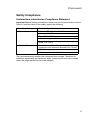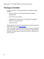
1
EZ ConnectTM 2.4 GHz
Wireless Ethernet Adapter
User Guide
From SMC’s EZ line of low-cost workgroup LAN solutions
38 Tesla
Irvine, CA 92618
Phone: (949) 679-8000
November 2003
150000024600E R01 F1.0
Copyright
Information furnished by SMC Networks, Inc. (SMC) is believed to be accurate and reliable.
However, no responsibility is assumed by SMC for its use, nor for any infringements of patents
or other rights of third parties which may result from its use. No license is granted by
implication or otherwise under any patent or patent rights of SMC. SMC reserves the right to
change specifications at any time without notice.
Copyright © 2003 by
SMC Networks, Inc.
38 Tesla
Irvine, CA 92618
All rights reserved.
Trademarks:
SMC is a registered trademark; and EZ Connect is a trademark of SMC Networks, Inc. Other
product and company names are trademarks or registered trademarks of their respective
holders.
COMPLIANCES
FCC - Class B
This equipment has been tested and found to comply with the limits for a Class B
digital device, pursuant to Part 15 of the FCC Rules. These limits are designed to
provide reasonable protection against harmful interference in a residential
installation. This equipment generates, uses, and can radiate radio frequency
energy and, if not installed and used in accordance with instructions, may cause
harmful interference to radio communications. However, there is no guarantee that
the interference will not occur in a particular installation. If this equipment does
cause harmful interference to radio or television reception, which can be
determined by turning the equipment off and on, the user is encouraged to try to
correct the interference by one or more of the following measures:
• Reorient the receiving antenna
• Increase the separation between the equipment and receiver
• Connect the equipment into an outlet on a circuit different from that to which the
receiver is connected
• Consult the dealer or an experienced radio/TV technician for help
FCC Caution: To assure continued compliance, (example - use only shielded
interface cables when connecting to computer or peripheral devices) any changes
or modifications not expressly approved by the party responsible for compliance
could void the user's authority to operate this equipment.
This device complies with Part 15 of the FCC Rules. Operation is subject to the
following two conditions: (1) This device may not cause harmful interference, and
(2) this device must accept any interference received, including interference that
may cause undesired operation.
IMPORTANT NOTE:
FCC Radiation Exposure Statement
FCC Radiation Exposure Statement: This equipment complies with FCC radiation
exposure limits set forth for an uncontrolled environment. This equipment should
be installed and operated with a minimum distance of 20 centimeters (8 inches)
between the radiator and your body. This transmitter must not be co-located or
operating in conjunction with any other antenna or transmitter.
i
COMPLIANCES
Industry Canada - Class B
This digital apparatus does not exceed the Class B limits for radio noise emissions
from digital apparatus as set out in the interference-causing equipment standard
entitled “Digital Apparatus,” ICES-003 of the Department of Communications.
Cet appareil numérique respecte les limites de bruits radioélectriques applicables
aux appareils numériques de Classe B prescrites dans la norme sur le matériel
brouilleur: “Appareils Numériques,” NMB-003 édictée par le ministère des
Communications.
EC Conformance Declaration
0560
SMC contact for these products in Europe is:
SMC Networks Europe,
Edificio Conata II,
Calle Fructuós Gelabert 6-8, 2o, 4a,
08970 - Sant Joan Despí,
Barcelona, Spain.
Marking by the above symbol indicates compliance with the Essential
Requirements of the R&TTE Directive of the European Union (1999/5/EC). This
equipment meets the following conformance standards:
• EN 60950 (IEC 60950) - Product Safety
• EN 300 328 - Technical requirements for 2.4 GHz radio equipment
• EN 301 489-1 / EN 301 489-17 - EMC requirements for radio equipment
Countries of Operation & Conditions of Use in the European
Community
This device is intended to be operated in all countries of the European
Community. Requirements for indoor vs. outdoor operation, license requirements
and allowed channels of operation apply in some countries as described below:
Note: The user must use the configuration utility provided with this product to
ensure the channels of operation are in conformance with the spectrum
usage rules for European Community countries as described below.
• This device requires that the user or installer properly enter the current country
of operation in the command line interface as described in the user guide,
before operating this device.
• This device will automatically limit the allowable channels determined by the
current country of operation. Incorrectly entering the country of operation may
result in illegal operation and may cause harmful interference to other system.
The user is obligated to ensure the device is operating according to the channel
limitations, indoor/outdoor restrictions and license requirements for each
European Community country as described in this document.
ii
COMPLIANCES
• This device may be operated indoors or outdoors in all countries of the
European Community using the 2.4 GHz band: Channels 1 - 13, except where
noted below.
- In Italy the end-user must apply for a license from the national spectrum
authority to operate this device outdoors.
- In France outdoor operation is only permitted using the 2.4 - 2.454 GHz band:
Channels 1 - 7.
Declaration of Conformity in Languages of the European
Community
English
Hereby, SMC Networks, declares that this Radio LAN device is in
compliance with the essential requirements and other relevant
provisions of Directive 1999/5/EC.
Finnish
Valmistaja SMC Networks vakuuttaa täten että Radio LAN device
tyyppinen laite on direktiivin 1999/5/EY oleellisten vaatimusten ja
sitä koskevien direktiivin muiden ehtojen mukainen.
Dutch
Hierbij verklaart SMC Networks dat het toestel Radio LAN device
in overeenstemming is met de essentiële eisen en de andere
relevante bepalingen van richtlijn 1999/5/EG
Bij deze SMC Networks dat deze Radio LAN device voldoet aan
de essentiële eisen en aan de overige relevante bepalingen van
Richtlijn 1999/5/EC.
French
Par la présente SMC Networks déclare que l'appareil Radio LAN
device est conforme aux exigences essentielles et aux autres
dispositions pertinentes de la directive 1999/5/CE
Swedish
Härmed intygar SMC Networks att denna Radio LAN device står
I överensstämmelse med de väsentliga egenskapskrav och
övriga relevanta bestämmelser som framgår av direktiv 1999/5/
EG.
Danish
Undertegnede SMC Networks erklærer herved, at følgende
udstyr Radio LAN device overholder de væsentlige krav og
øvrige relevante krav i direktiv 1999/5/EF
iii
COMPLIANCES
German
Hiermit erklärt SMC Networks, dass sich dieser/diese/dieses
Radio LAN device in Übereinstimmung mit den grundlegenden
Anforderungen und den anderen relevanten Vorschriften der
Richtlinie 1999/5/EG befindet". (BMWi)
Hiermit erklärt SMC Networks die Übereinstimmung des Gerätes
Radio LAN device mit den grundlegenden Anforderungen und
den anderen relevanten Festlegungen der Richtlinie 1999/5/EG.
(Wien)
Greek
iv
Italian
Con la presente SMC Networks dichiara che questo Radio LAN
device è conforme ai requisiti essenziali ed alle altre disposizioni
pertinenti stabilite dalla direttiva 1999/5/CE.
Spanish
Por medio de la presente SMC Networks declara que el Radio
LAN device cumple con los requisitos esenciales y cualesquiera
otras disposiciones aplicables o exigibles de la Directiva 1999/5/
CE
Portuguese
SMC Networks declara que este Radio LAN device está
conforme com os requisitos essenciais e outras disposições da
Directiva 1999/5/CE.
COMPLIANCES
Safety Compliance
Underwriters Laboratories Compliance Statement
Important! Before making connections, make sure you have the correct cord set.
Check it (read the label on the cable) against the following:
Operating Voltage
Cord Set Specifications
120 Volts
UL Listed/CSA Certified Cord Set
Minimum 18 AWG
Type SVT or SJT three conductor cord
Maximum length of 15 feet
Parallel blade, grounding type attachment plug
rated 15 A, 125 V
240 Volts (Europe only)
Cord Set with H05VV-F cord having three
conductors with minimum diameter of 0.75 mm2
IEC-320 receptacle
Male plug rated 10 A, 250 V
The unit automatically matches the connected input voltage. Therefore, no
additional adjustments are necessary when connecting it to any input voltage
within the range marked on the power adapter.
v
COMPLIANCES
Wichtige Sicherheitshinweise (Germany)
1. Bitte lesen Sie diese Hinweise sorgfältig durch.
2. Heben Sie diese Anleitung für den späteren Gebrauch auf.
3. Vor jedem Reinigen ist das Gerät vom Stromnetz zu trennen. Verwenden Sie
keine Flüssigoder Aerosolreiniger. Am besten eignet sich ein angefeuchtetes
Tuch zur Reinigung.
4. Die Netzanschlu ßsteckdose soll nahe dem Gerät angebracht und leicht
zugänglich sein.
5. Das Gerät ist vor Feuchtigkeit zu schützen.
6. Bei der Aufstellung des Gerätes ist auf sicheren Stand zu achten. Ein Kippen
oder Fallen könnte Beschädigungen hervorrufen.
7. Die Belüftungsöffnungen dienen der Luftzirkulation, die das Gerät vor
Überhitzung schützt. Sorgen Sie dafür, daß diese Öffnungen nicht abgedeckt
werden.
8. Beachten Sie beim Anschluß an das Stromnetz die Anschlußwerte.
9. Verlegen Sie die Netzanschlußleitung so, daß niemand darüber fallen kann.
Es sollte auch nichts auf der Leitung abgestellt werden.
10. Alle Hinweise und Warnungen, die sich am Gerät befinden, sind zu beachten.
11. Wird das Gerät über einen längeren Zeitraum nicht benutzt, sollten Sie es
vom Stromnetz trennen. Somit wird im Falle einer Überspannung eine
Beschädigung vermieden.
12. Durch die Lüftungsöffnungen dürfen niemals Gegenstände oder Flüssigkeiten
in das Gerät gelangen. Dies könnte einen Brand bzw. elektrischen Schlag
auslösen.
13. Öffnen sie niemals das Gerät. Das Gerät darf aus Gründen der elektrischen
Sicherheit nur von authorisiertem Servicepersonal geöffnet werden.
14. Wenn folgende Situationen auftreten ist das Gerät vom Stromnetz zu trennen
und von einer qualifizierten Servicestelle zu überprüfen:
a. Netzkabel oder Netzstecker sind beschädigt.
b. Flüssigkeit ist in das Gerät eingedrungen.
c. Das Gerät war Feuchtigkeit ausgesetzt.
d. Wenn das Gerät nicht der Bedienungsanleitung entsprechend funktioniert
oder Sie mit Hilfe dieser Anleitung keine Verbesserung erzielen.
e. Das Gerät ist gefallen und/oder das Gehäuse ist beschädigt.
f. Wenn das Gerät deutliche Anzeichen eines Defektes aufweist.
15. Stellen Sie sicher, daß die Stromversorgung dieses Gerätes nach der EN
60950 geprüft ist. Ausgangswerte der Stromversorgung sollten die Werte von
AC 7,5-8 V, 50-60 Hz nicht über oder unterschreiten sowie den minimalen
Strom von 1 A nicht unterschreiten.
Der arbeitsplatzbezogene Schalldruckpegel nach DIN 45 635 Teil 1000 beträgt
70 dB(A) oder weniger.
vi
TABLE OF CONTENTS
EZ Connect™ 2.4 GHz Wireless Ethernet
Adapter . . . . . . . . . . . . . . . . . . . . . . . . . . . . . . . . . . . 1
Introduction . . . . . . . . . . . . . . . . . . . . . . . . . . . . . . . . . . . . . 1
Package Checklist . . . . . . . . . . . . . . . . . . . . . . . . . . . . . . . . 2
Hardware Description . . . . . . . . . . . . . . . . . . . . . . . 3
Applications . . . . . . . . . . . . . . . . . . . . . . . . . . . . . . . . . . . . . 4
LED Indicators . . . . . . . . . . . . . . . . . . . . . . . . . . . . . . . . . . . 5
System Requirements . . . . . . . . . . . . . . . . . . . . . . . . . . . . . 6
Hardware Installation . . . . . . . . . . . . . . . . . . . . . . . 7
System Configuration . . . . . . . . . . . . . . . . . . . . . . . 8
EZ Installation Wizard . . . . . . . . . . . . . . . . . . . . . . . 9
Using IPCONFIG . . . . . . . . . . . . . . . . . . . . . . . . . . . . . . . . 10
Utility Installation and Configuration . . . . . . . . . 11
Using the Configuration Utility . . . . . . . . . . . . . . . . . . . . . . 12
Utility Configuration . . . . . . . . . . . . . . . . . . . . . . . . . . . . . . 13
System . . . . . . . . . . . . . . . . . . . . . . . . . . . . . . . . . . . . . . 13
IP Config . . . . . . . . . . . . . . . . . . . . . . . . . . . . . . . . . . . . . 15
Statistic . . . . . . . . . . . . . . . . . . . . . . . . . . . . . . . . . . . . . . 16
Wireless Operation . . . . . . . . . . . . . . . . . . . . . . . . . . . . . 17
Security . . . . . . . . . . . . . . . . . . . . . . . . . . . . . . . . . . . . . . 20
About . . . . . . . . . . . . . . . . . . . . . . . . . . . . . . . . . . . . . . . 24
Configuring Your IP Address . . . . . . . . . . . . . . . . 25
Windows 98/Me . . . . . . . . . . . . . . . . . . . . . . . . . . . . . . . . . 25
Windows 2000 . . . . . . . . . . . . . . . . . . . . . . . . . . . . . . . . . . 28
Windows XP . . . . . . . . . . . . . . . . . . . . . . . . . . . . . . . . . . . . 30
Web Management . . . . . . . . . . . . . . . . . . . . . . . . . 33
Browser Configuration . . . . . . . . . . . . . . . . . . . . . . . . . . . . 33
vii
TABLE OF CONTENTS
Disable Proxy Connection . . . . . . . . . . . . . . . . . . . . . . .
Internet Explorer (5.5 or above) in Microsoft Windows .
Internet Explorer in Macintosh . . . . . . . . . . . . . . . . . . . .
Navigating the Web Browser Interface . . . . . . . . . . . . . . .
Making Configuration Changes . . . . . . . . . . . . . . . . . . .
System . . . . . . . . . . . . . . . . . . . . . . . . . . . . . . . . . . . . . .
LAN . . . . . . . . . . . . . . . . . . . . . . . . . . . . . . . . . . . . . . . .
Wireless . . . . . . . . . . . . . . . . . . . . . . . . . . . . . . . . . . . . .
MAC Filter . . . . . . . . . . . . . . . . . . . . . . . . . . . . . . . . . . .
Tools . . . . . . . . . . . . . . . . . . . . . . . . . . . . . . . . . . . . . . .
Status . . . . . . . . . . . . . . . . . . . . . . . . . . . . . . . . . . . . . . .
33
33
33
34
34
36
37
38
46
47
51
Network Configuration and Planning . . . . . . . . .52
Network Topologies . . . . . . . . . . . . . . . . . . . . . . . . . . . . . .
Ad Hoc Wireless LAN . . . . . . . . . . . . . . . . . . . . . . . . . . .
Infrastructure Wireless LAN . . . . . . . . . . . . . . . . . . . . . .
Infrastructure Wireless LAN for Roaming Wireless PCs
A Wireless LAN with Internet Access . . . . . . . . . . . . . . .
52
52
53
54
55
Troubleshooting . . . . . . . . . . . . . . . . . . . . . . . . . .56
SMC Networks 802.11b Wireless Product
Maximum Distance Table . . . . . . . . . . . . . . . . . . . . . . . . . 57
Specifications . . . . . . . . . . . . . . . . . . . . . . . . . . . .58
Terminology . . . . . . . . . . . . . . . . . . . . . . . . . . . . . .60
viii
EZ CONNECT™ 2.4 GHZ
WIRELESS ETHERNET ADAPTER
Introduction
SMC’s EZ Connect 2.4 GHz Wireless Ethernet Adapter
(SMC2671W) can function as:
•
an Ethernet adapter, providing a wireless connection via an
RJ-45 connection to devices such as Microsoft Xbox and
Ethernet ready embedded devices
•
a standard IEEE 802.11b access point
•
a wireless range extender, allowing you to effectively extend
the coverage of another SMC2671W that is configured to
operate in Access Point mode
This solution offers fast, reliable wireless connectivity with
considerable cost savings over wired LANs (eliminates long-term
maintenance overhead for cabling). Just install enough wireless
access points to cover your network area, plug wireless cards into
your notebooks or install wireless adapters into your desktops,
and start networking.
Use this device in conjunction with SMC’s EZ Connect Wireless
Cards to create an instant network that integrates seamlessly
with Ethernet LANs. Moreover, moving or expanding your network
is as easy as moving or installing additional access points – no
wires!
1
EZ CONNECT™ 2.4 GHZ WIRELESS ETHERNET ADAPTER
Package Checklist
The EZ Connect 2.4 GHz Wireless Ethernet Adapter package
includes:
•
One EZ Connect 2.4 GHz Wireless Ethernet Adapter
(SMC2671W)
•
One 5 VDC power adapter
•
Installation CD containing this User Guide, EZ Installation
Wizard, and Utility program
•
One RJ-45 cable
Please register this product and upgrade the product warranty on
SMC’s web site at http://www.smc.com
Inform your dealer if there are any incorrect, missing, or damaged
parts. If possible, retain the carton, including the original packing
materials. Use them again to repack the product in case there is a
need to return it.
2
HARDWARE DESCRIPTION
The Wireless Ethernet Adapter supports 1, 2, 5.5 and 11 Mbps
half-duplex connections to Ethernet networks. This device is fully
compliant with 2.4 GHz DSSS CSMA/CA wireless networking as
defined in IEEE 802.11b. It can be connected via an RJ-45
connection to devices such as Nintendo GameCube, Microsoft
Xbox, Sony PlayStation II, and Ethernet ready embedded
devices. It can also function as an IEEE 802.11b Access Point or
as a Range Extender (see “Introduction” on page 1).
Power Connector
MDI/MDIX Switch
RJ-45 Port
Figure 1. Rear Panel
Item
Description
Power Inlet
Connect the included power adapter to this inlet.
Warning: Using the wrong type of power adapter may damage
your adapter.
LAN Port
Fast Ethernet port (RJ-45). Connect device (such as a PC, hub
or switch) on your local area network to this port.
MDI/MDIX
Switch
Press down the switch to connect to a network device with a
straight-through twisted-pair cable; otherwise, connect to the
network device with (MDI-X) station ports at both ends by using
crossover cabling.
Note: If you use the RELOAD button at the bottom, the Wireless
Ethernet Adapter performs a power reset. If the button is
depressed for over 5 seconds, all the LEDs will illuminate
and the factory settings will be restored.
3
HARDWARE DESCRIPTION
Applications
EZ Connect wireless products offer a fast, reliable, cost-effective
solution for wireless Ethernet client access to the network in
applications such as:
4
•
Video Game Systems
Provides wireless Internet access for users of video game
systems such as Nintendo GameCube, Microsoft Xbox and
Sony PlayStation II
•
Remote access to corporate network information
Email, file transfer, and terminal emulation
•
Difficult-to-wire environments
Historical or old buildings, asbestos installations, and open
areas where wiring is difficult to employ
•
Frequently changing environments
Retailers, manufacturers, and banks which frequently
rearrange the workplace or change locations
•
Temporary LANs for special projects or peak periods
Trade shows, exhibitions, and construction sites that need a
temporary setup. Retailers, airline, and shipping companies
that need additional workstations for peak periods. Auditors
who require workgroups at customer sites
•
Access to databases for mobile workers
Doctors, nurses, retailers, or white-collar workers who need
access to databases while being mobile in a hospital, retail
store, in an office, or on a campus
•
SOHO users
SOHO (Small Office and Home Office) users who need easy
and quick installation of a small computer network
LED INDICATORS
LED Indicators
The Wireless Ethernet Adapter includes three status LED
indicators, as described in the following figure and table.
Figure 2. Front Panel
LED
Status
Description
Wireless
Link
TX/RX
Flashing (Green)
The device is transmitting or receiving
data through wireless links.
Ethernet
Status
LNK/
ACT
On (Orange)
The device has established a valid
10 Mbps Ethernet link.
On (Green)
The device has established a valid
100 Mbps Ethernet link.
Flashing
The device is transmitting or receiving
data on the Ethernet LAN
On (Red)
Power is being supplied.
Power (PWR)
5
HARDWARE DESCRIPTION
System Requirements
Before you install the Wireless Ethernet Adapter, be sure you
have met the following requirements:
6
•
An AC power outlet (100~240 V, 50~60 Hz)
•
An available RJ-45 (UTP) port on an Ethernet hub or switch
•
802.11b compliant wireless Ethernet adapters with TCP/IP
protocols installed
•
TCP/IP network protocol installed on each PC that needs to
access the Internet
•
A web browser, such as Microsoft Internet Explorer 5.5 or
above installed on one PC at your site for configuring the
Wireless Ethernet Adapter
HARDWARE INSTALLATION
1. Select the site – Choose a location for your Wireless Ethernet
Adapter. Usually, the best location is at the center of your
wireless coverage area, if possible within line-of-sight of all
wireless devices.
2. Place the Wireless Ethernet Adapter in a position that gives it
maximum coverage. Normally, the higher you place the
antenna, the better the performance.
3. Position the antennas in the desired positions. For more
effective coverage, position the antennas along different axes.
For example, try positioning the antennas around 45 to 90
degrees apart. (The antennas emit signals along the
toroidal plane – and thus provide more effective
coverage when positioned along different axes.)
4. If used in Ethernet Adapter mode, connect the Ethernet cable
to the RJ-45 socket of the device that will communicate over a
wireless connection with an access point.
5. If used in Acces Point mode, connect the SMC2671W to an
Ethernet network device such as a hub or a switch using
category 3, 4, or 5 UTP Ethernet cable and an RJ-45
connector. (See “Hardware Description” on page 3 for MDI/
MDI-X cabling.)
6. Connect the power adapter cable to the 5 VDC power socket
on the rear panel.
Warning: Use only the power adapter supplied with the
SMC2671W.
7
SYSTEM CONFIGURATION
The SMC2671W is a Plug-and-Play device. This means that, in
most cases, you will not need to configure it.
The SMC2671W Wireless Ethernet Adapter includes an SNMP
agent that is accessible through an SNMP manager application
(Refer to “Using the Configuration Utility” on page 12.) The latest
version may be downloaded from the SMC web site specified on
the back cover of this manual.
The SMC2671W can be configured by a web browser, specifically
Internet Explorer 5.5 or above. Using the web management
interface, you can configure the Wireless Ethernet Adapter and
view statistics to monitor network activity.
Before you attempt to log into the SMC2671W’s web-based
administration, please verify the following.
1. Your browser is configured properly (see below).
2. Disable any firewall or security software that may be running.
3. Confirm that you have a good link LED where your computer
is plugged into the Wireless Ethernet Adapter. If you don’t
have a link light – then try another cable to get a good link.
4. To access the Internet through the Wireless Ethernet Adapter,
you must configure the network settings of the computers on
your LAN to use the same IP subnet as the Wireless Ethernet
Adapter. The default network settings for the Wireless
Ethernet Adapter are:
SMC2671W IP Address: 192.168.2.25
Subnet Mask: 255.255.255.0
8
EZ INSTALLATION WIZARD
To configure your SMC2671W, first verify that your computer has
an IP address in the same subnet as the SMC2671W. If you are
not familiar with this procedure, see the “Using IPCONFIG”
section below.
Note: The default IP address of the SMC2671W is 192.168.2.25.
1. Insert the SMC EZ Installation Wizard & Documentation CD
into your CD-ROM drive.
2. The EZ Installation Wizard will appear. Click “Configuration
Utility” to begin the utility installation and setup process.
9
EZ INSTALLATION WIZARD
Using IPCONFIG
1. Click the “Start” button, click “Run” and type “command.”
2. Press “OK” and a DOS command prompt will appear.
3. Type “ipconfig” and press enter.
4. Verify that your IP address is 192.168.2.xxx. If so, you can
now use the SMC EZ Installation Wizard to configure your
SMC2671W. If your IP subnet is different, please go to the
“Configuring Your IP Address” on page 25.
10
UTILITY INSTALLATION AND
CONFIGURATION
Note: This Configuration Utility is for Windows 98SE, Me, 2000,
and XP.
After clicking “Configuration Utility,” follow the on-screen
instructions to install the utility program.
11
UTILITY INSTALLATION AND CONFIGURATION
Using the Configuration Utility
1. Click Start/Programs/SMC2671W/SMC2671W Configuration
Utility.
2. The program will automatically scan for SMC2671W access
points on the network. If you want to subsequently detect all
access points on the network, click the Scan button. From the
list of detected SMC2671Ws, double-click on the IP address
of the unit you wish to configure. A dialogue box will prompt
you for the login password.
3. Enter the default password: smcadmin
12
UTILITY CONFIGURATION
Utility Configuration
System
The first screen displays System information.
Menu
Description
Device Information
Description
The model number of the unit
Mac Address
The MAC address of the SMC2671W
Regulatory
Domain
Countries have different regulations regarding the use of radio
frequencies. Select the correct domain for your location.
• Europe: ETSI
• US: FCC
Serial Number
The serial number of the SMC2671W
13
UTILITY INSTALLATION AND CONFIGURATION
14
Menu
Description
Administrator
Password
Sets the password for administrator access.
(Default: smcadmin)
Load Default
The Load Default button will reload the factory default settings.
Reset
The Reset button will reboot the SMC2671W.
Refresh/Apply
Once a configuration change has been made on a screen, be
sure to click the Refresh or Apply button at the bottom of the
screen to enable the new setting.
UTILITY CONFIGURATION
IP Config
Click on the IP Config tab to display and set up the IP settings of
the SMC2671W.
Menu
Description
Mac address
The MAC address of the SMC2671W.
IP address
Set the IP address for SMC2671W as required.
(Default: 192.168.2.25)
Subnet mask
Set the Subnet Mask as required. (Default: 255.255.255.0)
Gateway
Set the default gateway as required. (Default: 192.168.2.1)
DHCP Client
You can enable the DHCP Client function to automatically get
an IP Address, Subnet Mask, and Default Gateway from a
DHCP server in your network. (Default: Disabled)
Primary Port
The Fast Ethernet port (RJ-45)
15
UTILITY INSTALLATION AND CONFIGURATION
Statistic
The Statistic tab displays transmit and receive statistics for
Ethernet and wireless connections.
16
UTILITY CONFIGURATION
Wireless Operation
The Wireless Operation page allows you to set up the wireless
configurations.
Menu
Description
Wireless Settings
WLAN Interface WLAN interface allows you to set up a wireless LAN
communication environment. (Default: Enable)
SSID Broadcast Broadcast the SSID on the wireless network for easy
connection with client PCs. (Default: Disable)
Channel ID
Set the operating radio channel. (Default: 6)
Note: Available channel settings are limited by local
regulations which determine the available channels.
ESSID
Extended SSID. All wireless clients and the wireless access
points within a specific ESS must be configured with the same
SSID. (Default: ANY)
17
UTILITY INSTALLATION AND CONFIGURATION
Menu
Description
Device Name
The name of the wireless access point. (Default: SMC2671W)
Basic Rates
The highest rate specified is the rate the access point will use
when transmitting broadcast/multicast and management
frames. Available options are: 1, 2, 5.5, and 11 Mbps. (Default:
2 Mbps.)
Data Rates
Set the data rate transmitted from the SMC2671W. The lower
the data rate, the longer the transmission distance. Available
options are: 1, 2, 5.5, and 11 Mbps. (Default: 11)
Preamble Type The access points and client card drivers have a radio setting
for RF Preamble. If you are not sure whether all the clients and
access point radios in your wireless network support the Short
RF preamble, then leave this setting to the default (Long).
Beacon Interval The beacon signals allow the wireless devices to maintain
contact with each other. They may also carry
power-management information. (Default: 100)
RTS Threshold You may configure the access point to initiate an RTS frame.
If the packet size is smaller than the preset RTS threshold size,
the RTS/CTS mechanism will NOT be enabled. (Default: 2,347
which means Disabled)
Frag. Threshold The Fragmentation Threshold can be set between 256 and
2,346. If the packet size is smaller than the preset fragment
size, the packet will not be segmented. (Default: 2,346 which
means Disabled)
Operation Mode
18
Mode
This may be set to Access Point, Range Extender, or Ethernet
Adapter. (Default: Ethernet Adapter)
BSSID
Basic Service Set ID. The MAC address of the access point to
which the adapter is connected in an infrastructure network. In
an ad hoc network, the BSS ID is a random number generated
by the first adapter that communicates with other clients in the
network. The BSS ID of the other clients will then be set to the
same value.
UTILITY CONFIGURATION
Menu
Description
MAC Filtering
You can decide which wireless devices are allowed to connect
to the SMC2671W by adding the MAC address of allowed
clients. Wireless devices that are not in the table will be denied
access.
• Choose Enable MAC Filtering to enable the MAC Filter.
(Default: Disabled)
• Key in the MAC address of the Ethernet device which is
allowed to associate with the SMC2671W, and click Add.
Note: The format of the MAC address is 12 hexadecimal
digits, i.e., A~F & 0~9.
• Select the MAC address from the MAC Address List, and
click on the Delete button to remove the client address from
the SMC2671W.
Note: This table will be blank if the SMC2671W is set to
Ethernet Adapter mode since the Ethernet Adapter
has no clients but is itself the client of an associated
access point.
19
UTILITY INSTALLATION AND CONFIGURATION
Security
The Security screen provides you with a versatile encryption
method to prevent unauthorized access to your wireless network
and provide more secure data transmissions.
20
UTILITY CONFIGURATION
Menu
Description
Type
Encryption
WEP
WEP (mode)
Active (key)
Passphrase
Enabled/Disable WEP (Wired Equivalent Privacy) encryption.
(Default: None)
All clients and a wireless access point in the wireless network
must have the same WEP setting.
The SMC2671W supports shared key encryption with key
lengths of the 64-bit standard and 128-bit industry standard.
Choose a key from the generated keys.
For automatic 64-bit security, enter a passphrase. Four keys
will be generated (as shown below). Automatic 128-bit security
generates a single passphrase.
You may automatically generate encryption keys or manually
enter the keys. The bit key must be in hexadecimal.
(0~9, A~F, e.g., D7 0A 9C 7F E5.)
64-Bit Manual Entry
Key 1~4 - Each Key ID contains 10 HEX digits.
21
UTILITY INSTALLATION AND CONFIGURATION
128-Bit Manual Entry
Key ID contains 26 HEX digits.
64-Bit Auto Entry
22
UTILITY CONFIGURATION
128-Bit Auto Entry
23
UTILITY INSTALLATION AND CONFIGURATION
About
The About tab displays the product name, the software version
number of the SMC2671W Configuration management tool, and
SMC copyright information.
Note: Clicking the SMC logo on the screen takes you to the SMC
web site (www.smc.com) for the latest firmware download.
24
CONFIGURING YOUR IP
ADDRESS
Windows 98/Me
Note: Some Windows 9x/Me systems will request that you insert
your Windows CD in order to complete the following
configuration. Please have this CD ready.
1. Click the “Start” button and choose “Settings,” then click
“Control Panel.”
2. Double-click the “Network” icon.
25
CONFIGURING YOUR IP ADDRESS
3. Select the TCP/IP that is bound to the network adapter that
you are currently using to configure your SMC2671W. Click
“Properties.”
26
WINDOWS 98/ME
4. Select the “Specify an IP address” option and insert
192.168.2.x (where x is 2 ~ 24, 26 ~ 254). Then insert
255.255.255.0 for the subnet mask.
5. Press OK and reboot the machine when prompted to do so.
27
CONFIGURING YOUR IP ADDRESS
Windows 2000
1. Right-click the “Network Places” icon on your desktop and
click “Properties.”
2. Right-click your Local Area Connection and click “Properties.”
28
WINDOWS 2000
3. Click “Internet Protocol TCP/IP” and click “Properties.” Select
the “Use the following IP Address” option and insert
192.168.2.x (where x is 2 ~ 24, 26 ~ 254). Specify the default
gateway and DNS server as indicated by your network
administrator or Internet Service Provider.
4. Click “OK” and click “Close” to continue and save the
changes.
29
CONFIGURING YOUR IP ADDRESS
Windows XP
1. Right-click the “Network Places” icon on your desktop and
click “Properties.”
2. Right-click your “Local Area Connection” and click
“Properties.”
30
WINDOWS XP
3. Click “Internet Protocol TCP/IP” and click “Properties.”
31
CONFIGURING YOUR IP ADDRESS
4. Select the “Use the following IP Address” option and insert
192.168.2.x (where x is 2 ~ 24, 26 ~ 254) for the IP address.
Specify the default gateway and DNS server as indicated by
your network administrator or Internet Service Provider.
5. Click “OK” and click “Close” to continue and save the
changes.
32
WEB MANAGEMENT
Browser Configuration
Confirm that your browser is configured for a direct connection to
the Internet using the Ethernet cable that is installed in the
computer.
Disable Proxy Connection
You will also need to verify that the HTTP Proxy feature of your
web browser is disabled. This is so that your web browser will be
able to view the SMC2671W configuration pages. The following
steps are for Internet Explorer. Determine which browser you use
and follow the appropriate steps.
Internet Explorer (5.5 or above) in Microsoft Windows
1. Open Internet Explorer. Click Tools, and then select Internet
Options.
2. In the Internet Options window, click the Connections tab.
3. Click the LAN Settings button.
4. Clear all the check boxes and click OK to save these LAN
settings changes.
5. Click OK again to close the Internet Options window.
Internet Explorer in Macintosh
1. Open Internet Explorer. Click Explorer/Preferences.
2. In the Internet/Explorer/Preferences window, under Network,
select Proxies.
3. Uncheck all check boxes and click OK.
33
WEB MANAGEMENT
To access the SMC2671W’s
management interface, enter the
Wireless Ethernet Adapter IP
address in your web browser
http://192.168.2.25. Then enter the
password and click LOGIN.
(Default password: smcadmin)
The home page displays the Setup options.
Navigating the Web Browser Interface
The SMC2671W’s web management interface features a
user-friendly setup interface. This configuration UI supports
advanced functions like password setting, LAN IP setting,
wireless security configuration, MAC address filtering, firmware
upgrade, and other advanced functions.
Making Configuration Changes
Configurable parameters have a dialog box or a drop-down list.
Once a configuration change has been made on a page, be sure
to click the APPLY or REFRESH button at the bottom of the page
to enable the new setting.
Note: To ensure proper screen refresh after a command entry,
ensure that Internet Explorer 5.5 is configured as follows:
Under the menu Tools/Internet Options/General/
Temporary Internet Files/Settings, the setting for “Check
for newer versions of stored pages” should be “Every visit
to the page.”
34
NAVIGATING THE WEB BROWSER INTERFACE
Use the web management interface to define system parameters,
manage and control the Wireless Ethernet Adapter and its ports,
or monitor network conditions. The following table outlines the
selections available from this program.
Menu
Description
System
Sets the password for administrator access
LAN
Sets the TCP/IP configuration of the Wireless Ethernet
Adapter’s LAN interface and DHCP setup
Wireless
Configures the wireless channel, SSID, and encryption for
wireless communications
MAC Filter
Configures access to your network clients based on the MAC
(Media Access Control) address of the client machine
Tools
Contains options to backup and restore the current
configuration, restore all configuration settings to the factory
defaults, update system firmware, or reset the system
Displays WAN and Ethernet traffic statistics
Status
Displays WAN/LAN connection status, firmware, and hardware
version numbers
35
WEB MANAGEMENT
System
Password Settings
Use this menu to restrict access based on a password. (Default:
smcadmin). For security reasons, you should change the default
password before exposing the SMC2671W to the Internet.
Passwords can contain from 3 to 12 alphanumeric characters and
are not case-sensitive.
Enter a maximum Idle Time Out (in minutes) to define a
maximum period of time for which the login session is maintained
during inactivity. If the connection is inactive for longer than the
maximum idle time, it will be logged out, and you have to log in to
the web management system again. (Default: 10 minutes)
36
NAVIGATING THE WEB BROWSER INTERFACE
LAN
With “Obtain an IP Address Automatically [DHCP]” enabled, the
IP address, subnet mask and default gateway can be dynamically
assigned to the SMC2671W by the network DHCP server.
Note: If there is no DHCP server on your network, then the
SMC2671W will automatically start up with its default IP
address, 192.168.2.25.
The SMC2671W does not provide DHCP service. It simply
passes client DHCP requests through to the DHCP server to
obtain an IP Address.
If your Internet Service Provider has assigned a fixed IP address,
select “Configure a Static IP Address.” Enter the assigned
address and subnet mask for the SMC2671W. Then enter the
gateway address of your ISP.
You may need a fixed address if you want to provide Internet
services, such as a web server or FTP server.
37
WEB MANAGEMENT
Wireless
To configure the SMC2671W as an Ethernet Adapter, all you
need to do is define the radio channel, the Service Set Identifier
(SSID), and encryption options.
In Ethernet Adapter mode or Range Extender mode, the radio
channel and SSID (Service Set ID) of the SMC2671W must be
set to the same values as those of the access point with which
they are associated.
If the SMC2671W is in Access Point mode, you must specify a
common radio channel and SSID (Service Set ID) to be used by
the Wireless Ethernet Adapter and all of your wireless clients. Be
sure you configure all of your clients to the same values.
38
NAVIGATING THE WEB BROWSER INTERFACE
Wireless Channel: The radio channel through which a wireless
access point communicates with PCs in its BSS. (Default: 6)
Note: The available channel settings are limited by local
regulations which determine the number of channels that
are available.
• USA: 1 ~ 11 channels
• Europe: 1 ~ 13 channels
• Japan: 1 ~ 14 channels
SSID: The Service Set ID. This should be set to the same value
as other wireless devices in your network. (Default: ANY)
Note: The SSID is case-sensitive and can consist of up to 32
alphanumeric characters.
Broadcast SSID: In Access Point Mode or Range Extender Mode,
the SMC2671W can be enabled to broadcast the SSID on the
wireless network for easy connection with client PCs.
(Default: Enable)
WEP Encryption
If you are transmitting sensitive data across
wireless channels, you should enable Wired
Equivalent Privacy (WEP) encryption.
Encryption requires you to use the same set of encryption/
decryption keys for a wireless access point and all of its wireless
clients. The SMC2671W supports shared key encryption with key
lengths of the 64-bit standard and 128-bit industry standard. The
bit key must be in hexadecimal.
(0~9, A~F, e.g., D7 0A 9C 7F E5.)
39
WEB MANAGEMENT
64-Bit Manual Entry
Key 1~4 - Each Key ID contains 10 HEX digits.
128-Bit Manual Entry
Key ID contains 26 HEX digits.
You may automatically generate encryption keys or manually
enter the keys. For automatic 64-bit security, enter a passphrase.
Four keys will be generated (as shown above). Choose a key
from the four generated keys. Automatic 128-bit security
generates a single passphrase.
Note that Wired Equivalent Privacy (WEP) protects data
transmitted between wireless nodes, but does not protect any
transmissions over your wired network or over the Internet.
40
NAVIGATING THE WEB BROWSER INTERFACE
Client List
The Client List screen displays the MAC address and network
speed of the associated clients.
41
WEB MANAGEMENT
Advanced Settings
Operation Mode: This may be set to Access Point,
Range Extender or Ethernet Adapter.
(Default: Ethernet Adapter)
Note: After you choose the operation mode for the SMC2671W,
be sure to click the APPLY button, and click OK on the
confirmation message to enable the new setting.
These modes are described below:
42
•
Access Point – functions as a standard IEEE 802.11b access
point
•
Range Extender – repeats data from another SMC2671W that
is configured in Access Point mode
•
Ethernet Adapter – provides a wireless connection to devices
such as Microsoft Xbox and Ethernet ready embedded
devices
NAVIGATING THE WEB BROWSER INTERFACE
The parameters that follow may be configured in any of the three
modes described above but the user is advised to leave them at
their default settings.
Transmission Rate : Set the data rate transmitted
from the Wireless Ethernet Adapter. The lower the
data rate, the longer the transmission distance.
(Default: Auto)
RTS Threshold : Set the RTS (Request to Send) frame length.
You may configure the access point to initiate an RTS frame. If
the packet size is smaller than the preset RTS threshold size, the
RTS/CTS mechanism will NOT be enabled.
The access point sends Request to Send (RTS) frames to a
particular receiving station to negotiate the sending of a data
frame. After receiving an RTS, the station sends a CTS (Clear to
Send) frame to acknowledge the right of the sending station to
send data frames. The access points contending for the medium
may not be aware of each other. The RTS/CTS mechanism can
solve this “Hidden Node Problem.” (Default: 2347)
Fragmentation Threshold : The Fragmentation Threshold can be
set between 256 and 2,346. If the packet size is smaller than the
preset Fragment size, the packet will not be segmented.
Fragmentation of the PDUs (Package Data Units) can increase
the reliability of transmissions because it increases the probability
of a successful transmission due to smaller frame size. If there is
significant interference present, or collisions due to high network
utilization, try setting the fragment size to send smaller fragments.
This will make the retransmission of smaller frames much faster.
However, it is more efficient to set the fragment size larger if very
little or no interference is present because it requires overhead to
send multiple frames. (Default: 2346)
43
WEB MANAGEMENT
Basic Rate : The highest rate specified is the rate
the Wireless Ethernet Adapter will use when
transmitting broadcast/multicast and management
frames. (Default: 1, 2 Mbps.)
Preamble Type : The access points and client card drivers have a
radio setting for for a long or short RF preamble. Preamble Type
offers a drop-down list with two options: Long or Short. Using the
short preamble can boost your throughput. If you are not sure
whether all the clients and access point radios in your wireless
network support the Short RF preamble, then leave this setting to
the default (Long).
Transmit Power : Set the signal strength transmitted from
the access point. The longer the transmission distance,
the higher the transmission power required.
(Default: Super)
Selections - Low, Medium, Normal, High and Super
44
NAVIGATING THE WEB BROWSER INTERFACE
Site Survey
In Ethernet Adapter mode, the Site Survey scans and shows all
IEEE 802.11b wireless devices within the adapter’s signal range.
You can choose one of them to connect to by clicking on an
(B)SSID entry.
BSSID : Basic Service Set ID. The MAC address of the access
point to which the adapter is connected in an infrastructure
network. In an ad hoc network, the BSS ID is a random number
generated by the first adapter that communicates with other
clients in the network. The BSS ID of the other clients will then be
set to the same value.
Channel : The radio channel on which the access point operates.
45
WEB MANAGEMENT
WEP : WE security protects your wireless LAN against
eavesdropping and unauthorized access by intruders. If WEP is
in use, all clients on the same network must use the same WEP
key settings in order to communicate with each other.
SSID : The Service Set ID of the scanned access points.
MAC Filter
The MAC Filtering feature of the SMC2671W allows you to
control access to your network clients based on the MAC (Media
Access Control) Address of the client machine. This ID is unique
to each network adapter. If MAC address filtering is enabled, then
the MAC address for each client must be listed in the table to
allow access to the network.
46
NAVIGATING THE WEB BROWSER INTERFACE
Tools
Use the Tools menu to back up the current configuration, restore
a previously saved configuration, restore factory settings, update
firmware, and reset the SMC2671W.
Configuration Tools
•
Backup Settings – Saves the SMC2671W’s configuration to a
file.
•
Restore Settings – Restores settings from a saved backup
configuration file.
•
Restore to Factory Defaults – Restores the SMC2671W
settings back to the original factory defaults.
47
WEB MANAGEMENT
Firmware Upgrade
Use this screen to update the firmware or user interface to the
latest version. Download the upgrade file from the web site and
save it to your hard drive. Click Browse to look for the previously
downloaded file. Click APPLY.
Check the Status page Information section to confirm that the
upgrade process was successful.
48
WEB MANAGEMENT
Reset
Click APPLY to reset the SMC2671W. Your settings will not be
changed. The reset will be complete when the power LED is lit
red.
49
WEB MANAGEMENT
Statistics
The Statistics page displays transmit and receive statistics for all
associated stations.
50
WEB MANAGEMENT
Status
The Status screen displays WAN/LAN connection status,
firmware, and hardware version numbers of the SMC2671W.
51
NETWORK CONFIGURATION
AND PLANNING
The Wireless Solution supports a stand-alone wireless network
configuration, as well as an integrated configuration with 10 Mbps
Ethernet LANs. For a list of the maximum distances between the
AP/Bridge and wireless clients, refer to page 57.
The wireless network cards and adapters can be configured as:
•
•
Ad hoc – for small departmental or SOHO LANs
Infrastructure – for enterprise LANs
Network Topologies
Ad Hoc Wireless LAN
An ad hoc wireless LAN
consists of a group of
computers, each equipped
with a wireless adapter or
SMC2671W Ethernet
Adapter, connected via
radio signals as an
independent wireless
LAN. Computers in a
specific ad hoc wireless LAN must be configured to the same
radio channel.
An ad hoc wireless LAN can be used for a small branch office or
SOHO operation.
52
NETWORK TOPOLOGIES
Infrastructure Wireless LAN
An integrated wired and wireless LAN is called an infrastructure
configuration. A Basic Service Set (BSS) consists of a group of
wireless PC users, and an access point that is directly connected
to the wired LAN. Each wireless PC in this BSS can talk to any
computer in its wireless group via a radio link, or access other
computers or network resources in the wired LAN infrastructure
via the access point.
The infrastructure configuration permits wireless clients to access
the wired LAN and also increases the effective wireless
transmission range for wireless clients as their signal can be
passed through multiple access points.
A wireless infrastructure can be used for access to a central
database, or for connection between mobile workers, as shown in
the following figure.
53
NETWORK CONFIGURATION AND PLANNING
Infrastructure Wireless LAN for Roaming Wireless PCs
The Basic Service Set (BSS) is the communications domain for
each wireless access point. For wireless PCs that do not need to
support roaming, set the domain identifier (SSID) of the wireless
card to the SSID of the access point to which you want to
connect. Check with your administrator for the SSID of the access
point to which he wants you to connect.
A wireless infrastructure can also support roaming for mobile
workers. More than one access point can be configured to create
an Extended Service Set (ESS). By placing the access points so
that a continuous coverage area is created, wireless users within
this ESS can roam freely. All wireless network cards, adapters,
and the wireless access point within a specific ESS must be
configured with the same SSID.
Note: If Access Point 2 is replaced by an SMC2671W set to
Range Extender mode then the SMC2671W will not
establish its own BSS, but will repeat data messages
between Access Point 1 and end users, thus extending
the coverage area of Access Point 1.
54
NETWORK TOPOLOGIES
A Wireless LAN with Internet Access
In this application one SMC2671W is in Ethernet Adapter mode
connected to a Microsoft Xbox. Another SMC2671W is acting in
Access Point mode. This provides a wireless network and also
Internet access for applications including Internet game playing.
55
TROUBLESHOOTING
Check the following items before you contact technical support.
1. If mobile users do not have roaming access to the
SMC2671W:
Make sure that all the SMC2671Ws and stations in the ESS
in which the WLAN mobile users can roam are configured to
the same WEP setting, SSID, and authentication algorithm.
2. If the management utility cannot connect to the SMC:
Check that your local IP address settings conform to the
SMC2671W settings.
3. If you forgot your password or your SMC2671W has locked
up, you can reset it to factory defaults by performing the
following steps:
56
•
Use a pin to push in the RELOAD button for 5 seconds.
This button is located on the bottom of the SMC2671W.
•
The SMC2671W will begin to load the default settings.
•
The SMC2671W will restart with the factory default
settings.
SMC NETWORKS 802.11B WIRELESS PRODUCT MAXIMUM DISTANCE
SMC Networks 802.11b Wireless Product
Maximum Distance Table
Important Notice
Maximum distances posted below are actual tested distance
thresholds. However, there are many variables such as barrier
composition and construction, as well as local environmental
interference that may impact your actual distances and cause you
to experience distance thresholds far lower than those posted
below. If you have any questions or comments regarding the
features or performance of this product, or if you would like
information regarding our full line of wireless products, visit us at
www.smc.com, or call us toll-free at 800.SMC.4YOU. SMC
Networks stands behind every product sold with a 30-day
satisfaction guarantee and a limited-lifetime warranty.
SMC2602W 802.11b Wireless PCI Card Maximum Distance Table
Speed and Distance Ranges
Environmental Condition
11 Mbps
5.5 Mbps
2 Mbps
Outdoors: A line-of-sight
environment with no
interference or obstruction
between the Access Point and
users.
1 Mbps
160 m
(528ft)
195 m
(640 ft)
255 m
(837 ft)
350 m
(1155 ft)
Indoors: A typical office or
home environment with floor to
ceiling obstructions between the
Access Point and users.
72 m
(236 ft)
73 m
(240 ft)
73 m
(240 ft)
75 m
(246 ft)
57
SPECIFICATIONS
Standards
Ethernet: 802.3 Ethernet or 802.3u Fast Ethernet for 10BASE-T/
100BASE-TX (RJ-45)
Radio: IEEE 802.11b
Operating Channels
IEEE 802.11b compliant
USA & Canada: 1 ~ 11 channels,
Europe (ETSI): 1 ~ 13 channels,
Japan: 1 ~ 14 channels
Data Rate
1, 2, 5.5, 11 Mbps
Operating Frequency
USA, Canada, and Europe (ETSI): 2400-2483.5 MHz
Japan: 2400-2497 MHz
Modulation Type
CCK, BPSK, and QPSK
Radio Technology
Direct Sequence Spread Spectrum
Power Supply
Input: 100-240 AC, 50-60 Hz
Output: 5 VDC, 1A
Power Consumption
5 V, 700 mA maximum
Receive Sensitivity
Minimum -87 dBm for 1 Mbps
Minimum -85 dBm for 2 Mbps
Minimum -83 dBm for 5.5 Mbps
Minimum -80 dBm for 11 Mbps
Output Power
> +18dBm minimum
Physical Size
14.30 x 12.20 x 3.03 cm (5.63 x 4.80 x 1.19 in.)
Weight
150 g (5.3 oz)
58
SPECIFICATIONS
LED Indicators
Power, Ethernet Link/Activity,
Wireless Activity (TX/RX)
Antenna
Two 2.0 dBi omni-directional dipole antennas
Network Management
Windows 98SE/Me/2000/XP SNMP Management Utility
Operating System Compatibility
Windows 98SE/Me/2000/XP
Supported Protocol
TCP/IP, IPX
Encryption
64-bit/128-bit WEP
Passphrase key generation
Temperature
Operating: 0 to 50 °C (32 to 122 °F)
Storage: 0 to 70 °C (32 to 158 °F)
Humidity
5% to 85% (non-condensing)
Compliances
CE Mark
EN55022 Class B
EN55024
IEC 61000-42/3/4/6/11
Emissions
FCC Part 15 Class B
ETSI 300.328
ARIB STD33 and T66
59
TERMINOLOGY
The following is a list of terminology that is used in this document.
Access Point – An internetworking device that seamlessly
connects wired and wireless networks.
Ad Hoc – An ad hoc wireless LAN is a group of computers each
with LAN adapters, connected as an independent wireless LAN.
Backbone – The core infrastructure of a network. The portion of
the network that transports information from one central location
to another central location where it is unloaded onto a local
system.
Base Station – In mobile telecommunications, a base station is
the central radio transmitter/receiver that maintains
communications with the mobile radio telephone sets within its
range. In cellular and personal communications applications,
each cell or micro-cell has its own base station; each base station
in turn is interconnected with other cells’ bases.
BSS – BSS stands for “Basic Service Set.” It is an Access Point
and all the LAN PCs that are associated with it.
CSMA/CA – Carrier Sense Multiple Access with Collision
Avoidance.
ESS – ESS (ESS-ID, SSID) stands for “Extended Service Set.”
More than one BSS is configured to become an Extended
Service Set. LAN mobile users can roam between different BSSs
in an ESS (ESS-ID, SSID).
60
TERMINOLOGY
Ethernet – A popular local area data communications network,
which accepts transmission from computers and terminals.
Ethernet operates on a 10 Mbps baseband transmission rate,
using a shielded coaxial cable or shielded twisted pair telephone
wire.
Infrastructure – An integrated wireless and wired LAN is called
an Infrastructure configuration.
Fragmentation Threshold – In the 802.11 Standard, the MAC
Layer may fragment and reassemble directed MSDUs or
MMPDUs. The fragmentation and defragmentation mechanisms
allow for fragment re-transmission.
Preamble Type – Some access points and client card drivers
have a radio setting for “Short” RF Preamble. If all the clients and
access points in your wireless network have this feature, then
enabling it can boost your throughput. However, if a radio does
not support this feature, then it will not be able to communicate
with any other radios that have this set to “Short.”
Roaming – A wireless LAN mobile user moves around an ESS
and maintains a continuous connection to the infrastructure
network.
RTS Threshold – Transmitters contending for the medium may
not be aware of each other. RTS/CTS mechanism can solve this
“Hidden Node Problem.” If the packet size is smaller than the
preset RTS Threshold size, the RTS/CTS mechanism will NOT be
enabled.
WEP – “Wired Equivalent Privacy” is based on the use of 64-bit or
128-bit keys and the popular RC4 encryption algorithm. Wireless
devices without a valid WEP key will be excluded from network
traffic.
61
TERMINOLOGY
62
FOR TECHNICAL SUPPORT, CALL:
From U.S.A. and Canada (24 hours a day, 7 days a week)
(800) SMC-4-YOU; Phn: (949) 679-8000; Fax: (949) 679-1481
From Europe : Contact details can be found on
www.smc-europe.com or www.smc.com
INTERNET
E-mail addresses:
[email protected]
[email protected]
Driver updates:
http://www.smc.com/index.cfm?action=tech_support_drivers_downloads
World Wide Web:
http://www.smc.com
http://www.smc-europe.com
FOR LITERATURE OR ADVERTISING RESPONSE, CALL:
U.S.A. and Canada:
(800) SMC-4-YOU;
Spain:
34-91-352-00-40;
UK:
44 (0) 1932 866553;
France:
33 (0) 41 38 32 32;
Italy:
39 (0) 335 5708602;
Benelux:
31 33 455 72 88;
Central Europe:
49 (0) 89 92861-0;
Nordic:
46 (0) 868 70700;
Eastern Europe:
34 -93-477-4920;
Sub Saharian Africa:
216-712-36616;
North West Africa:
34 93 477 4920;
CIS:
7 (095) 7893573;
PRC:
86-10-6235-4958;
Taiwan:
886-2-8797-8006;
Asia Pacific:
(65) 238 6556;
Korea:
82-2-553-0860;
Japan:
81-45-224-2332 ;
Australia:
61-2-8875-7887;
India:
91-22-8204437 ;
Fax (949) 679-1481
Fax 34-93-477-3774
Fax 44 (0) 118 974 8701
Fax 33 (0) 41 38 01 58
Fax 39 02 739 14 17
Fax 31 33 455 73 30
Fax 49 (0) 89 92861-230
Fax 46 (0) 887 62 62
Fax 34 93 477 3774
Fax 216-71751415
Fax 34 93 477 3774
Fax 7 (095) 789 35 73
Fax 86-10-6235-4962
Fax 886-2-8797-6288
Fax (65) 238 6466
Fax 82-2-553-7202
Fax 81-45-224-2331
Fax 61-2-8875-7777
Fax 91-22-8204443
If you are looking for further contact information, please visit www.smc.com,
www.smc-europe.com, or www.smc-asia.com.
38 Tesla
Irvine, CA 92618
Phone: (949) 679-8000
Model Number: SMC2671W
Revision Number E112003-R01 F 1.0
Part Number: 150000024600E