1
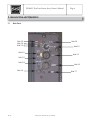
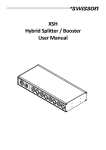
PLS8695 Powered True Line Source Array
Owner’s Manual
Rev: 512
1650 W. Jackson Ozark, MO 65721 (417) 883-4549
PLS8695 True Line Source Array Owner’s Manual
Page 2
1. Important Safety Instructions
1.1
CAUTION
To reduce the risk of electric shock, do not remove the back panel of the PLS8695. There are no user-serviceable
parts inside. Refer servicing to SLS Loudspeakers or qualified personnel.
1.2
General Safety
1.2.1
Read and follow all warnings, operating and safety instructions in this manual and on the unit.
1.2.2
Do not use the PLS8695 near bathtubs, sinks, swimming pools, or other locations where water is present.
1.2.3
The speakers should be positioned firmly on a level surface. Make sure that the supporting object can
handle the load weight of the PLS8695.
1.2.4
The line voltage selection switch must be set for the correct AC voltage present in the region of use
(115VAC or 230VAC). Operating the speaker outside these voltages or opposite of the selector switch
setting may damage the electronics.
1.2.5
For continued protection against risk of fire, replace only with same type of fuse and rating for operational
voltage selection.
1.2.6
Do not place the PLS8695 near heat sources such as stoves, heat registers, radiators, or other appliances
that produce heat.
1.2.7
Power supply cords should be placed so that they will not be pinched by objects being placed on or against
them.
1.2.8
During extended periods of non-use, the power cord should be unplugged from the outlet.
1.2.9
Do not expose the PLS8695 to rain or moisture. Fire or electrical shock may result.
1.3
Compliance
This device complies with part 15 of the FCC Rules. Operation is subject to the following two conditions: (1) This
device may not cause harmful interference, and (2) this device must accept any interference received, including
interference that may cause undesired operation
Rev: 512
1650 W. Jackson Ozark, MO 65721 (417) 883-4549
PLS8695 True Line Source Array Owner’s Manual
Page 3
2. Introduction
2.1
Welcome to SLS
Thank you for choosing SLS Loudspeakers! SLS Loudspeakers is a leader in digital amplification and ribbon
technology allowing for a new level of sound reproduction, clarity, and definition. Should you need to contact SLS
you can visit our website at www.slsaudio.com or contact our headquarters:
SLS Loudspeakers
1650 W. Jackson
Ozark, MO 65721
417-883-4549
2.2
Proprietary Technology
Various technologies and components within the PLS8695 are proprietary to SLS and protected under letters
patent.
2.3
Unpacking
The PLS8695 loudspeakers are individually shipped in heavy-duty cardboard boxes and are protected inside by
foam packing material.
Step 1: Cut sealing tape on bottom or top end, fold the carton flaps back and invert box and contents.
Step 2: Lift the carton carefully clear of inner contents.
Note: do not cut through carton with sharp objects, as you might damage cabinet finish.
We suggest you retain the packaging for possible future use
Rev: 512
1650 W. Jackson Ozark, MO 65721 (417) 883-4549
PLS8695 True Line Source Array Owner’s Manual
Page 4
3. General Use and Operation
3.1
Back Panel
Note 3.8
Note 3.8
Note 3.8
Note 3.8
Note 3.6
Note 3.11
Note 3.4
Note 3.11
Note 3.10
Note 3.4
Note 3.9
Rev: 512
Note 3.7
1650 W. Jackson Ozark, MO 65721 (417) 883-4549
PLS8695 True Line Source Array Owner’s Manual
3.2
Page 5
Positioning
The PLS8695 has a very defined vertical dispersion, which helps prevent interaction with the floor and ceiling and
extends the nearfield listening area. It is important to set the speaker so the bottom of the box is approximately at
chest height of the first listeners. The speaker may be tilted for proper positioning relative to the coverage area. It
is highly recommended that our free LASS aiming software be used to set the position and angle of the
PLS8695(s).
3.3
AC Mains Connection
The AC mains power cord is connected to the front panel through the blue Neutrik Powercon. The mating cable end
connector is a Neutrik NAC3FCA. The grey Powercon connector is a power outlet that allows looping to adjacent
PLS8695’s. The looping outlet mating cable connector is a Neutrik NAC3FCB. Up to (2) PLS8695’s can be used on
a single 20 amp circuit.
3.4
Audio Connection
The PLS8695 accepts a balanced audio signal at the XLR audio input connector located on the back panel. Pin 3
is high signal. The input is transformer balanced with an input impedance of 15K Ohms. Connect an appropriate
XLR cable between an audio source (mixer, processor, etc.) to the balanced input connector. Unbalanced connections can be accomplished by grounding pin 2 or 3 of the XLR audio input connector through the use of an appropriate adapter or cable. A buffered loop output is provided for additional PLS8695s and/or active subwoofers.
3.5
Power Connection
Prior to connecting the power cord and turning on the amplifier, always verify the line voltage selection switch is set
for the correct AC voltage present in the region of use. The PLS8695 is designed to operate on either 115VAC or
230VAC by using the line voltage selection switch. Damage may occur to the electronics if the speaker is powered
up with the line voltage selector switch in the incorrect position. Once set to the proper range, the amplifier will
regulate the internal voltages so that output power does not change with supply voltage.
3.6
Audio Level Control
The PLS8695 is equipped with a detented audio level control for use in setting the overall audio level. Set this
control to the desired position based upon the nominal gain structure desired.
3.7
80Hz High Pass Filter (in - disabled; out - enabled)*
The PLS8695 is equipped with an 80Hz 2nd-order Butterworth high pass filter for use in applications having a
subwoofer or for restricting the low frequencies in speech only systems. The filter may be enabled or disabled by
using the 80Hz HPF switch located on the back panel.
Rev: 512
1650 W. Jackson Ozark, MO 65721 (417) 883-4549
PLS8695 True Line Source Array Owner’s Manual
3.8
Page 6
Status Indicators
“CLIP” indicates when Channel 1 is clipping. “PROT” indicates when the power supply protective circuitry has been
engaged. It may be necessary to cycle the power to reset the protective circuitry. “PWR” indicates that power is
present in the amplifier. “SIG” indicates that signal is present at the input of the amplifier.
3.9
Programming Port
This port is used by SLS to program the EEPROM for DSP processing data. It requires a proprietary interface and
is not user assessable.
3.10
Programming Selection
This switch allows the selection between two different EQ settings stored in EEPROM. Pushed in is optimized for a
single PLS8695. Pushed out is optimized for two PLS8695s stacked on top of each other. This is "boot up"
enabled so in order to make the EQ change: power off the PLS8695, select the button position desired and repower. It will boot up with the selected EQ programming.
3.11
Mute Switches (in - signal passes, out - muted)*
These switches mute the individual amplifier channels for setup and troubleshooting purposes.
* Buttons are reversed from typical settings to protect them from damage when they are in typical positions.
4. Specifications
Product Specifications
Operating Range
80 – 20,000Hz
Horizontal Coverage Angle -6dB
120 Degrees
Vertical Coverage Angle
Defined by height of the array
Input Sensitivity
1.88V RMS
Max SPL (calculated) @ 1 Meter
130dB peak
Amplifier Power High Freq.
500 Watts
Amplifier Power Low Freq.
1000 Watts
AC Power Consumption
11 amps at full rated output
Crossover Frequency
1500Hz
Transducers – High Freq.
9 x PRD500 Ribbons
Low Freq.
8 x 6.5 Woofers
55.5” (141cm)H
11.5” (29.2cm)W
Dimensions
12” (30.5cm)D
Weight
110lbs (50kg)
Rugged weather resistant latex
Enclosure
paint - in black, white, or
paintable natural birch
Rev: 512
1650 W. Jackson Ozark, MO 65721 (417) 883-4549