1
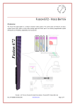
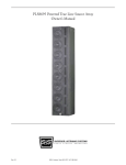
Power Management Products
Watson Installation and User’s manual
©Copyright Leprecon LLC. 2013
All rights reserved
Publication 21-1050 Rev C
This document is the property of Leprecon LLC, and is provided for service and instructional purposes
only. Possession does not imply or convey rights to use any information herein. This information is
proprietary, and may relate to patents or patents pending that are the properties of CAE, Inc. other than the
use of products manufactured by CAE, Inc.
Table of Contents
Front panel Controls: Watson W1 ................................................................................3
1) Introduction .................................................................................................................4
2) Features and Specifications ........................................................................................4
Power Connection........................................................................................................4
Ambient Temperature...................................................................................................4
Load Connector ...........................................................................................................4
DMX Control input........................................................................................................5
3) Installation...................................................................................................................6
Mounting ......................................................................................................................6
Power Connection........................................................................................................6
Load Connection..........................................................................................................6
4) Turning on Power........................................................................................................6
5) Front Panel Controls ...................................................................................................7
Address Menu:.............................................................................................................7
Mode Menu ..................................................................................................................9
Delay Menu................................................................................................................10
Software Version........................................................................................................11
6) Troubleshooting and Service.....................................................................................12
Service policy.............................................................................................................12
Warranty Information..................................................................................................12
7) DMX 512 Information ................................................................................................13
Connectors ................................................................................................................13
Cable type..................................................................................................................13
2
Front panel Controls: Watson W1
DMX output
DMX Input
Isolated DMX output
3
1) Introduction
Watson provides two important functions to support new technology (non-incandescent)
lighting fixtures.
1) Power Switching – using a set DMX address, or simply detecting DMX signal,
Watson will turn off the power to fixtures when they are not in use.
2) Isolated DMX data – Watson provides optically isolated and buffered signal for a
series of DMX fixtures.
Please take a few minutes to review the specifications features of the new Watson
product.
2) Features and Specifications
Power Connection
Power input Connector
Mating connector
Operating voltage
Maximum load current
Neutrik PowerCon
Neutrik NAC3FCA
110 – 240 VAC
15 amps
Ambient Temperature
Watson Power Management systems are designed to operate in an environment where
the ambient temperature is less than 40 degrees Celsius, or 104 degrees Fahrenheit.
Load Connector
Depending on the model purchased, your Watson Power System will use either
Powercon or standard NEMA 5-15 load connectors. Please note that Powercon
connectors are NOT designed to be connected under load. Please turn off the circuit
breaker on Watson before connecting power or load. PowerCON load connector is
Neutrik NAC3MPB-1, and the mating cable mount connector is NAC3FCB.
4
DMX Control input
All Watson models accept DMX 512 1990 as specified by USITT. Reliable DMX systems
require cable rated for data communication at 250K baud; for this reason the use of
microphone cable is NOT recommended. DMX rated cables are available premanufactured from your Leprecon dealer. For more information on the DMX standard
and acceptable cable, see the Appendix at the end of this manual.
For convenience, DMX in and out connectors are provided on the Watson front panel.
This allows easy connection to additional dimmer packs. The DMX standard allows up to
32 devices to be connected to a single DMX controller.
5
3) Installation
Mounting
Each Watson system ships with a simple metal bracket that will accept a standard C
clamp. The packaging for the bracket includes the screws that are needed to attach the
bracket to the Watson chassis.
Power Connection
For full current operation, 12 gauge power cords are recommended to power Watson
and the fixtures downstream. Leprecon can supply NEMA 5-15 to Powercon cables in
several lengths.
Load Connection
Fixtures or other devices connected to the output of Watson can be turned off remotely.
The powered devices are protected by an internal circuit breaker on the Watson unit. To
prevent overload, make sure that the total wattage of devices connected to Watson is
less than 15 amps.
4) Turning on Power
Watson has one line cord and circuit breaker. When power is applied, and the breaker is
turned on, the breaker will be illuminated by a green pilot lamp. When first powered, the
red display on the Watson front panel will light.
Note:
Watson is designed to turn off the display after a short delay with no activity. Even if the
display is not lighted, Watson is still operational.
6
5) Front Panel Controls
Watson uses a 4 digit display and four entry switches to set operating modes, and show
the operating status.
Address Menu:
When the unit is first turned on, the display shows the DMX address. This is the DMX
address that can be used to turn loads on and off
When there is no DMX input, the address number is preceded by a dash ( - ).
-.001
When valid DMX is detected, the dash is replaced with the letter ‘d’ for DMX:
d.001
The UP/DOWN keys change the value for the start address. Watson uses the changed
value immediately and permanently saves it after 10 seconds or if the Enter or Menu key
is pressed.
7
After power on, the ULD-360 remains in the Address Menu . If no buttons are pressed,
the display will blank after about 15 seconds.
If Watson is in ‘Automatic’ mode, it will turn on when DMX is present, and off when data
is not present. Since this operation does not need a start address, Watson shows blanks
on power up:
-- --
8
Mode Menu
The Mode Menu sets the way Watson performs power switching.
Press the Menu button once to enter set the operating mode:
C1:nd
The display shows C1, then the selected mode.
Set the mode for the displayed address by pressing the UP/DOWN buttons. The
possible modes are:
Mode
Nd
Au
Of
On
Description
Non- dim. DMX level above 60% turns on the output. When the DMX
level is below 40% the output is off
Output switched on whenever DMX is present.
Output permanently off (test mode)
Output permanently on (test mode)
After changing the mode the colon will blink to indicate new data has been entered.
Pressing the ENTER key saves the change.
Watson returns to the main display automatically after 4 seconds if no keys are pressed
in the Mode Menu.
9
Delay Menu
The Non-Dim and Auto switch modes use a delay time to prevent immediate power
switching. This can be useful in two situations:
1) Momentary signal loss or accidental changes will not turn off fixtures.
2) Device turn on can be delayed to sequence power on for multiple units. This can
minimize the disturbance on the power system.
From the main menu, press the Menu button twice. The Delay menu is indicated by the
first two display characters Dl.
Dl:01
Delay times are represented in seconds, and can be set from 01 to 99 seconds.
Dl:99
10
Software Version
From the main display, pressing the Menu key three times will display the current
software version. In the example below, the software version is 2.02
U2:02
d1:00
ο1:ΦΦ
11
6) Troubleshooting and Service
Service policy
Watson is designed for a long, trouble free life. If you suspect that you have a problem,
the first step is to check all other system components and connections.
Specific problems and solutions are listed below:
Problem
No power
No response to DMX
Shorted load
No DMX signal
No output
Overload
Indication
Solution
breaker not lighted
check incoming power
Display shows D, but no Check address assignment and
output
operating mode
breaker trips
repair instrument or cable
Display shows ‘-‘
Check cable and controller
Loads off
Test with ‘On’ mode
breaker trips
check wattage of loads
If a problem is suspected with Watson, contact your Leprecon dealer for service.
Because of the high voltages present inside of the system, it is important that only
qualified personnel do all service. Substandard repairs can create a dangerous
condition.
Warranty Information
For a period of two years from the date of sale, Leprecon LLC will replace any defective parts and
will repair any defective module returned to the factory prepaid, without charge for parts or labor.
Damage caused by misuse, incorrect line voltage or connection to shorted loads is not covered
under warrany.
Please consult your dealer for full warranty details.
The Leprecon service department may be reached at 810-231-9373 during business hours, or a
message may be left after hours. Our fax number is 810-231-1631.
Our service department must first authorize any return to the factory. Do not return any
equipment without calling for an authorization number.
12
7) DMX 512 Information
The following information is a summary of the USITT 1990 standard for dimmers and
controllers. A complete copy may be obtained from:
USITT
10 W. 19th ST.
Suite 5A
New York, NY 10011-4206
Several web sites exist that have an abundance of information regarding DMX-512. As
with any Internet information, consider the source.
The DMX 512 standard is designed as a simple, reliable system for connecting digital
dimmers and controllers. The protocol allows up to 512 dimmers to be connected to a
single control console. With 512 dimmers in a system, DMX 512 allows each dimmer
level to be updated 44 times each second.
Connectors
The DMX standard specifies the use of 5 pin XLR connectors. DMX 512 currently uses 3
pins of the 5 pin connector. Pins 4 and 5 are reserved for future use. Some
manufacturers are using these pins for communications back from the dimmer to the
control console, or as a redundant data line.
The connectors to be used for DMX 512 are as follows:
Console end (transmitter)
Dimmer end (receiver)
Female 5 pin XLR
Male 5 pin XLR
Some manufacturers of XLR connectors are Switchcraft, ITT Cannon, and Neutrik.
Cable type
Shielded twisted pair approved for EIA-422/EIA-485 use. Either one pair with shield or
two pair with shield may be used. Examples of such cable are:
Single pair: Belden 9841, Alpha 5271
Two pairs: Belden 9842, Alpha 5272
The Pin Designations for DMX 512 are as follows:
Pin 1
Pin 2
Pin 3
Pin 4
Pin 5
Signal common (cable shield)
Data 1Data 1+
Spare, optional Data 2Spare, optional Data 2+
13