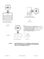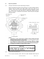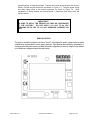
1
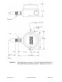
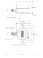
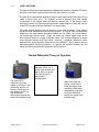
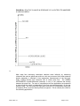
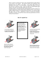
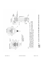
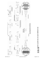
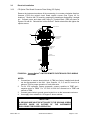
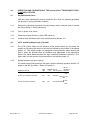
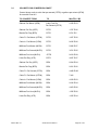
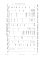
INNOVA-SWITCH™ SERIES
INSTRUCTION MANUAL
Model 215 Mass Flow/Level Switch
( Model FS4200 Series – Mass Flow Switch / Model LS3200 Series – Point Level Switch )
Document IM 215
Rev-A.1
February 2006
Sierra Instruments, Inc., Headquarters
5 Harris Court, Building L
Monterey, California, USA 93940
Toll Free: 800-866-0200 (USA only)
Phone: 831-373-0200 ; Fax: 831-373-4402
Website: www.sierrainstruments.com
Sierra Europe, European Headquarters
Bijlmansweid 2
1934RE Egmond a/d Hoef
The Netherlands
Phone: +31 72 5071 400 ; Fax: +31 72 5071 401
Sierra Asia, Asia-Pacific Headquarters
100 Jaingnan Daidao Suite 2303
Guangzhou, China
Phone: +86 20 3435 4870, Fax: +86 20 3435 4872
BEFORE STARTING
SIERRA INSTRUMENTS appreciates your choosing our product for your liquid level or liquid/gas flow
switching application. We are committed to providing reliable, quality instrumentation to our customers.
To ensure the maximum and intended benefit of this instrument, we encourage you to read this brief
operation and maintenance manual in its entirety prior to unpacking and installing the unit.
The following precautions should be noted immediately:
•
WHEN INSTALLING YOUR INNOVA-SWITCH™ INTO A PIPE OR VESSEL USE A 1 1/8 INCH
(28.575mm) OPEN-END WRENCH TO TIGHTEN AT THE HEX FLATS OF THE MNPT OF A
STANDARD SWITCH. (IF YOU HAVE A NON-STANDARD SWITCH AN ALTERNATE SIZE
WRENCH MAY BE REQUIRED). DO NOT USE THE INSTRUMENT HEAD TO TIGHTEN THE
SWITCH TO THE MOUNTING PORT. ROTATION OF THE INSTRUMENT HEAD WITH
RESPECT TO THE SENSOR BODY CAN CAUSE INTERNAL WIRING DAMAGE (SEE
FIGURES 1).
•
THE SWITCH BODY MUST BE ORIENTED TO HAVE THE TWIN SENSORS PARALLEL TO
THE LEVEL BEING DETECTED WHEN THE SENSOR IS INSTALLED HORIZONTALLY FOR
POINT LEVEL APPLICATIONS. LIKEWISE, FOR FLOW APPLICATIONS, THE SWITCH
BODY MUST BE ORIENTED TO HAVE THE TWIN SENSORS PERPENDICULAR TO THE
FLOW BEING DETECTED.
DUE TO THE PIPE THREAD MOUNTING, IT MAY BE
NECESSARY TO MAKE A TRIAL FIT, ADD OR REMOVE TEFLON TAPE OR OTHER PIPE
THREAD SEALANT, AND REINSTALL TO ACHIEVE A SATISFACTORY SEAL WITH THE
SENSORS PROPERLY ORIENTED. FOR VERTICAL INSTALLATION OF SENSORS FOR
POINT LEVEL DETECTION THE ORIENTATION MAKES NO DIFFERENCE. PROPER
ORIENTATION IS MARKED ON THE SWITCH BODY FOR REFERENCE (SEE FIGURE 5).
•
A GROUND WIRE MUST BE ATTACHED TO THE GROUND SCREW LOCATED INSIDE THE
INSTRUMENT ENCLOSURE FOR PROPER OPERATION. FOR CENELEC/CE OPTION THE
GROUND SCREW IS LOCATED OUTSIDE THE BODY OF THE INSTRUMENT ENCLOSURE
(SEE FIGURE 6).
•
BE SURE TO APPLY THE PROPER VOLTAGE AS CONFIGURED AT THE FACTORY. DO
NOT APPLY 115 VAC TO 24 VDC VERSIONS OR 24 VDC TO 115 VAC VERSIONS.
(LIKEWISE 230 VAC).
•
FOR OPTIMUM OPERATION, CALIBRATION MUST BE ACCOMPLISHED AT ACTUAL
PROCESS TEMPERATURE AND PRESSURE CONDITIONS IN GASES AND AT ACTUAL
PROCESS TEMPERATURE CONDITIONS IN LIQUIDS.
•
DO NOT SANDBLAST OR ABRASIVE CLEAN THE SENSING PROBES.
PROBES COULD BE DAMAGED BY ABRASIVES.
•
ALL DIMENSIONS GIVEN IN THIS MANUAL ARE IN INCHES (AND MILLIMETERS).
THE SENSING
If you have any questions prior to or during installation and calibration, please do not hesitate to call the
factory for assistance. We want to ensure the very best possible installation and operational results for
your benefit.
IM-215 Rev-A.1
Series Innova-Switch™
Page 2 of 42
NOTICE
This manual covers the following model numbers:
Innova-Switch™ Series Models
215 - FS4200
215 - LS3200
Agency Approvals
Explosion-Proof rating
Mass Flow Switch
FS42CN
Point Level Switch
LS32CN
CENELEC
European
EEX d IIB T4 (Killark Enclosure)
EEx d IIC T4 (Akron Electric
Enclosure)
See Figure 1A and 1B
CSA
Canadian Standards
T4A
Class I, Group B,C,D
Class II, Group E, F, G
(Both Akron Electric and Killark)
FS42CS
LS32CS
Non-Approved
Non-Explosion Proof
FS42NX
LS32NX
(Ref. Section CE 3.2.3
wiring)
EMC Directive: 89/336/EEC
Option-CE
Option-CE
SPECIAL NOTICE
The electronic assemblies contained in the Innova-Switch™ models are configured for specific
voltages and have specific modifications to accommodate the various agency approvals. When
ordering spare electronics, replacements, or exchanges in the field please ensure you identify the
specific configuration you have by noting the boxes marked on the transformer configuration tag.
IM-215 Rev-A.1
Series Innova-Switch™
Page 3 of 42
TABLE OF CONTENTS
1.0
INTRODUCTION
2.0
DESCRIPTION
3.0
4.0
5.0
2.1
LEVEL SWITCHING
2.2
FLOW SWITCHING
INSTALLATION
3.1
MECHANICAL INSTALLATION
3.2
ELECTRICAL INSTALLATION
3.2.1
LOCAL ELECTRONICS (LE OPTION/STANDARD)
3.2.2
REMOTE ELECTRONICS (RE) OPTION
3.2.3
CE OPTION FILTER BOARD CONNECTOR PLATE WIRING (CE OPTION)
OPERATION AND CALIBRATION OF THE Innova-Switch™ SWITCH FOR FLOW APPLICATIONS
4.1
PRE-OPERATIONAL CHECKS
4.2
L.E.D. AND RELAY STATUS LOGIC (FAIL-SAFE)
4.3
CALIBRATION – FLOW
OPERATION AND CALIBRATION OF THE Innova-Switch™ SWITCH FOR POINT LEVEL
APPLICATIONS
6.0
5.1
PRE-OPERATIONAL CHECKS
5.2
L.E.D. AND RELAY STATUS LOGIC (FAIL-SAFE)
5.3
CALIBRATION – LEVEL
MAINTENANCE AND TROUBLE SHOOTING
6.1
CLEANING
6.2
TROUBLE SHOOTING
6.2.1 POWER AND CONTINUITY VERIFICATION
6.2.2 SENSOR/ELECTRONICS FUNCTIONALITY VERIFICATION
7.0
SPECIFICATIONS
8.0
WARRANTY AND SERVICE
9.0
10
8.1
WARRANTY
8.2
SERVICE
8.3
SPARE PARTS LIST
APPENDIX
9.1
VOLUME FLOW CONVERSION CHART
9.2
FLOW CONVERSION CHART
9.3
FLOW OF WATER THROUGH SCHEDULE 40 STEEL PIPE (AVAILABLE IN PRINTED
MANUAL ONLY)
OPTIONS
10.1
LIVETAP (LT)
10.2
VARIABLE INSERTION (VI)
10.3
THERMOCOUPLE OUTPUT (TO)
10.4
RTD OUTPUT(RT)
10.5
SANITARY (3A1)
IM-215 Rev-A.1
Series Innova-Switch™
Page 4 of 42
1.0
INTRODUCTION
™
The SIERRA INSTRUMENTS Innova-Switch Switch is the state-of-the-art in
gaseous and liquid flow switching or liquid level control. Flow or level detection is
accomplished by using a high resolution thermal differential technique. The sensor
wetted parts are of durable 316L series stainless steel, all welded construction with
no moving parts. The switch is easy to install and adjust, giving reliable, low
maintenance performance in the most demanding applications.
2.0
DESCRIPTION
™
The Innova-Switch uses a thermal differential technique to sense changes in the
heat transfer characteristics of a media. Figures 1A and 1B show the outline of the
™
Innova-Switch . The sensor consists of a pair of matched Resistance Temperature
Detectors (RTD's) encased in twin 316L series stainless steel tubes. One RTD is
self-heated using a constant DC current. The other RTD is unheated to provide an
accurate process temperature reference. The thermal differential created between
the heated and reference RTD pair is a function of the density and/or velocity of the
media with which the sensor is in contact. Other physical properties may have a
secondary effect as well. The differential is greatest at a no flow (or dry) condition
and decreases as the rate of flow increases (or as a liquid quenches the sensor/wet
condition).
The SIERRA INSTRUMENTS sensor excitation method relies on constant current to
the heated and reference sensors. Thus power to the heated sensor is not constant
but changes linearly with temperature as the sensor resistance changes.
Temperature compensation is accomplished by using the amplified reference sensor
voltage that also changes linearly with temperature, as a dynamic reference. During
calibration dry/no flow and wet/full flow conditions are impressed across the trip point
potentiometer. Since this reference is not fixed but is set with respect to the
reference sensor voltage, as temperature changes the trip point potentiometer
voltage changes with temperature exactly the same as that of the heated sensor
voltage with which it is being compared. Thus full temperature compensation is
achieved with non-constant power.
IM-215 Rev-A.1
Series Innova-Switch™
Page 5 of 42
FIGURE 1A
IM-215 Rev-A.1
LS3200/FS4200 Innova-Switch™ OUTLINE DIAGRAM STANDARD 2.0
INCH INSERTION (KILLARK ENCLOSURE – NEMA 4-EExd 11B, T4)
Series Innova-Switch™
Page 6 of 42
FIGURE 1B
IM-215 Rev-A.1
LS3200/FS4200 Innova-Switch™ OUTLINE DIAGRAM STANDARD 2.0
INCH INSERTION (AKRON ELECTRIC ENCLOSURE – NEMA 4X –
EexdIIC, T4)
Series Innova-Switch™
Page 7 of 42
2.1
LEVEL SWITCHING
The thermal differential created between the heated and reference unheated RTD pair is
a function of the liquid or gas medium with which the sensor is in contact.
The point level measurement application uses the heat transfer differences between two
media to detect liquid level. For example, air has a relatively poor heat transfer
characteristic so the heated sensor will become relatively hot. If the sensor is then
immersed in water, the relatively high heat transfer characteristics of water will cool the
heated RTD surface causing a decrease in the signal output.
This same rational applies for any two media in contact with the sensor. Each medium
will have its own characteristic heat transfer properties. As long as there is a reasonable
difference in the heat transfer properties between the two media, the Innova-Switch™
can discriminate between them. Figure 2A shows the relative signal output of the
Innova-Switch™sensor to a range of different media. The maximum difference in output
occurs between vacuum and liquid metal. However, a significant difference occurs
between water and hydrocarbon liquids so the Innova-Switch ™ can be used to detect a
water/hydrocarbon liquid-liquid interface. In general, the interface between any two
media with differing heat transfer properties can be detected.
Thermal Differential Theory of Operation
Note: Probe tips contain
matched RTD’s one of
which is self-heated with
about 400mw of power.
The other provides
temperature
compensation.
The heated RTD
responds to the heat
transfer coefficient of the
media with which it is in
contact. Gases with low
heat transfer result in a
high differential
temperature between the
heated and reference tips.
IM-215 Rev-A.1
When the heated tip
makes contact with a
liquid with higher heat
transfer the differential
temperature drops and
the lower differential
results in a switch trip to
indicate liquid.
Series Innova-Switch™
Page 8 of 42
FIGURE 2A: RELATIVE CHANGE IN RESPONSE OF A HEATED RTD IMMERSED
IN VARIOUS MEDIA
2.2
Flow Switching
Most mass flow monitoring techniques calculate mass indirectly by measuring
volumetric flow such as gallons per minute or cubic cm per second, then either measure
density separately or calculate it from temperature measurements of the fluid and,
finally, combine density and volumetric flow to obtain mass flow. The SIERRA
INSTRUMENTS thermal-differential technique is one of two methods that directly
measure the mass flow. For ease of comparison most flow applications are presented
in terms of velocity which is independent of the flow cross sectional area (i.e. feet per
second (FPS)). The true mass flow equivalent would be FPS multiplied by density but
for simplicity FPS is used and density effects are ignored. This is normally not critical for
flow switching applications.
IM-215 Rev-A.1
Series Innova-Switch™
Page 9 of 42
When the sensor is inserted into a liquid or gas the heated RTD is strongly affected
by the velocity of the medium. Flow past the heated RTD changes the heat
transferred from the surface of the sensor. This cooling effect reduces the
temperature of the sensor. The Innova-Switch™ compares this change to a preset
flow trip point to switch the output. Figure 2B shows the model FS4200 signal
change vs. flow rate for air, light hydrocarbon liquids, and water.
The signal change vs velocity has the same general shape for all three media but the
change is larger for air and the sensitive range is different for each. For air and most
gaseous media the range is 0.1 to 500 feet per second (FPS). For most liquid media
the range is 0.01 to 5 FPS. Appendices in section 9.0 contain flow conversion
information to facilitate conversion from various units and pipe dimensions into flow
velocity in feet per second.
Gas Or Liquid Flow
For a no flow condition the
thermal differential between
the two tips is high because of
relatively low heat transfer.
Note: The fluid velocity and
heat absorption ability
determine the differential
between the tips. Their
combination determines the
measurable velocity. In
water velocities from 0.01 to
5 FPS are measurable,
whereas in air velocities of
0.1 to 500 FPS can be
measured.
When the lower differential
matches the customer select
flow velocity trip point (set
point) the switch relay and
red LED are tripped.
IM-215 Rev-A.1
Flow across the tips decreases
the thermal differential
because of the higher heat
transfer of flowing fluids. This
differential is compared with
the trip point.
When flow is above the trip
point the differential is smaller
than at the set point and the
relay and Led remain tripped.
Series Innova-Switch™
Page 10 of 42
FIGURE 2B Innova-Switch™ MODEL FS4200 FLOW RESPONSE FOR THREE MEDIA
IM-215 Rev-A.1
Series Innova-Switch™
Page 11 of 42
Figure 3.A shows a block diagram of the Innova-Switch™ switch.
Once the switch is set to respond to the minimum and maximum flow rates (or wet vs.
dry conditions), the trip point is set by adjusting the Trip Adjust Potentiometer. Solid
state electronics transform the flow (or wetting) induced temperature differential into a
voltage that is compared to a control voltage. Matching voltages cause actuation of a
relay to indicate a change in state (flow vs. no-flow or dry vs. wet).
FIGURE 3A:
IM-215 Rev-A.1
Innova-Switch™ SERIES S BLOCK DIAGRAM MODELS
LS32CS/FS42CS, LS32CN/FS42CN, LS32NX/FS42NX
Series Innova-Switch™
Page 12 of 42
Figure 3B shows a block diagram of the Innova-Switch™ with the addition of an EMC filter
required for the CE options (see section 7.0).
FIGURE 3B: Innova-Switch™ MODELS WITH THE CE OPTION SWITCH BLOCK DIAGRAM
IM-215 Rev-A.1
Series Innova-Switch™
Page 13 of 42
The instrument enclosure at the top of unit contains the Innova-Switch™ electronics board
which is removable to access the terminal block and facilitate field wiring (see Figure 4.0). For
applications where the electronics must be located away from the sensors due to elevated
process temperature, accessibility, etc., another instrument head containing the electronics is
remotely located (See option RE-Remote Electronics section 3.2.2).
FIGURE 4
IM-215 Rev-A.1
Innova-Switch™ SWITCH ASSEMBLY
Series Innova-Switch™
Page 14 of 42
3.0
Installation
3.1
Mechanical Installation
The standard Innova-Switch™ has a .75 inch (19.05mm) MNPT mount designed for
easy installation through a threaded port. Optional configurations include .5”
(12.7mm) or 1.0” (25.4mm) MNPT and flange mounts. Conduit is recommended for
all wiring to the switch.
*IMPORTANT*
WHEN INSTALLING YOUR SIERRA INSTRUMENTS SWITCH INTO
A PIPE OR VESSEL USE A 1 1/8 INCH (28.575mm) OPEN-END
WRENCH TO TIGHTEN AT THE HEX FLATS OF THE MNPT OF A
STANDARD SWITCH. (IF YOU HAVE A NON-STANDARD SWITCH
AN ALTERNATE SIZE WRENCH MAY BE REQUIRED). DO NOT
USE THE INSTRUMENT HEAD TO TIGHTEN THE SWITCH TO THE
MOUNTING PORT. ROTATION OF THE INSTRUMENT HEAD WITH
RESPECT TO THE SENSOR BODY CAN CAUSE INTERNAL
WIRING DAMAGE.
*IMPORTANT*
THE SWITCH BODY MUST BE ORIENTED TO HAVE THE TWIN
SENSORS PROPERLY ORIENTED. DUE TO THE PIPE THREAD
MOUNTING, IT MAY BE NECESSARY TO MAKE A TRIAL FIT, ADD
OR REMOVE TEFLON TAPE OR OTHER PIPE THREAD SEALANT,
AND REINSTALL TO ACHIEVE A SATISFACTORY SEAL WITH
THE SENSORS PROPERLY ORIENTED. PROPER ORIENTATION
IS MARKED ON THE SWITCH BODY FOR REFERENCE. SEE
FIGURE 5.0 FOR DETAILS.
IM-215 Rev-A.1
Series Innova-Switch™
Page 15 of 42
FIGURE 5:
IM-215 Rev-A.1
PROPER ORIENTATION OF THE SENSOR PROBE FOR LEVEL
AND FLOW APPLICATION IS INDICATED BY THE ARROW ON
THE FLAT OF THE MOUNTING FITTING.
Series Innova-Switch™
Page 16 of 42
3.2
Electrical Installation
3.2.1
CE Option Filter Board Connector Plate Wiring (CE Option)
Remove the instrument enclosure lid by unscrewing in a counter clockwise direction.
Unscrew (CCW) the printed circuit board captive screws (See Figure 4.0 for
locations). Remove the PC board by grasping the transformer and pulling it straight
out. Connect power and alarm relay wiring to Terminal Block (TBB) as shown in
Figures 6.0 and 6.0A. Reinstall the Innova-Switch™ Switch electronics and tighten
the captive screws.
FIGURE 6.0
Innova-Switch™ SWITCH LOCAL ELECTRONICS FIELD WIRING
DIAGRAM
NOTES:
1. Connections to sensors terminal block A (TBA) are factory installed and should
not be disconnected in the field. Note Jumpers 1-2, 3-4, and 5-6 must be in place
on TBA for proper operation of local electronics.
2. For 24 VDC operation (factory prepared), connect +positive to TBB7 and –negative
return to TBB8. For 115 VAC or 230 VAC connect hot to TBB7 and neutral to TBB8.
3. Connect ground wire to ground screw located in or on the instrument enclosure.
4. Use supply wires suitable for 10 Degrees C above ambient.
*IMPORTANT*
A GROUND WIRE MUST BE ATTACHED TO THE GROUND SCREW
LOCATED INSIDE OR OUTSIDE OF THE INSTRUMENT
ENCLOSURE FOR PROPER OPERATION.
3.2.2
Remote Electronics (RE Option)
For the remote electronics option, mount the remote instrument head using two
IM-215 Rev-A.1
Series Innova-Switch™
Page 17 of 42
mounting wings or bracket provided. Connect the switch wiring between the InnovaSwitch™ Switch remote electronics as shown in Figure 7.0. Connect power wiring
and alarm relay wiring to the remote enclosure as shown in Figure 7.0. Upon
completion of wiring reinstall the Innova-Switch™ electronics and secure with the
captive screws.
*IMPORTANT*
BE SURE TO APPLY THE PROPER VOLTAGE AS CONFIGURED
AT THE FACTORY. DO NOT APPLY 115 VAC TO 24 VDC
VERSIONS OR 24 VDC TO 115 VAC VERSIONS (LIKEWISE 230
VAC).
SPECIAL NOTICE
The electronic assemblies contained in the Innova Switch™ are configured for specific voltages and have specific
modifications to accommodate the various agency approvals. When ordering spare electronics, replacements, or
exchanges in the field please ensure you identify the specific configuration you have by noting the boxes marked
on the transformer configuration tag and the serial number.
IM-215 Rev-A.1
Series Innova-Switch™
Page 18 of 42
IM-215 Rev-A.1
Series Innova-Switch™
Page 19 of 42
FIGURE 7A
WIRING
Innova Switch FLOW SWITCH REMOTE ELECTRONICS OPTION FIELD
IM-215 Rev-A.1
Series Innova-Switch™
Page 20 of 42
FIGURE 7B REMOTE ELECTRONICS CABLE TERMINATION AND
CONNECTIONS
3.2
Electrical Installation
3.2.3
CE Option Filter Board Connector Plate Wiring (CE Option)
Remove the instrument enclosure lid by unscrewing in a counter clockwise direction.
Unscrew (CCW) the printed circuit board captive screws (See Figure 4.0 for
locations). Remove the PC board by grasping the transformer and pulling it straight
out. Connect power and alarm relay wiring to Terminal Block (TBB) as shown in
Figures 6.0 and 6A. Reinstall the Innova-Switch™ Switch electronics and tighten the
captive screws.
POWER
RELAY CONTACTS
GNDEARTH
CAUTION:Usesupply wires suitable
for 10°Cabovesurroundingambient.
TBB
N H
- +
POWER
C N N
O C
REL1-1
C N N
O C
DM#101654
REL1-2
REMOTE ELECTRONICS
FILTER CONN PLATE
(CE OPTION)
TBA
1 2 3 4 5 6
SHIELDS CONNECTED
TO TERMINAL 5 AT
THIS END
3 TWISTED
SHIELDED PAIRS CABLE
SHIELDS
FLOATING AT
THIS END
1 2 3 4 5 6
HOT
SENSOR
FIGURE 6A
COLD
SENSOR
REMOTE PROBE
Innova-Switch™ SWITCH REMOTE ELECTRONICS FIELD WIRING
DIAGRAM
NOTES:
1. Connections to sensors terminal block A (TBA) are factory installed and should
not be disconnected in the field. Note Jumpers 1-2, 3-4, and 5-6 must be in
place on TBA for proper operation of local electronics.
2. For 24 VDC operation (factory prepared), connect +positive to TBB7 and –
negative return to TBB8. For 115 VAC or 230 VAC connect hot to TBB7 and
neutral to TBB8.
3. Connect ground wire to ground screw located in or on the instrument enclosure.
4. Use supply wires suitable for 10 Degree C above ambient.
*IMPORTANT*
A GROUND WIRE MUST BE ATTACHED TO THE GROUND SCREW
LOCATED INSIDE OR OUTSIDE OF THE INSTRUMENT
ENCLOSURE FOR PROPER OPERATION.
IM-215 Rev-A.1
Series Innova-Switch™
Page 21 of 42
4.0
OPERATION AND CALIBRATION OF THE Innova-Switch™ FS4200 SWITCH FOR
FLOW APPLICATIONS
4.1
Pre-Operational Check
With the switch installed and process conditions at no-flow, the following procedure
can be used to verify preliminary operation.
4.1.1
Remove the instrument enclosure cover by turning counter clockwise (ccw) to expose
the Innova-Switch™ Switch electronics.
4.1.2
Turn on power at its source.
4.1.3
Observe that either the red or green LED comes on.
4.1.4
If neither lamp illuminates refer to the trouble shooting Section, 6.2.
4.2
L.E.D. and Relay Status Logic (Fail-safe)
4.2.1
The L.E.D.s (Red; Green) are an indication of the sensors status (ie. flow below the
setpoint or flow above the set point) and are not affected by the position of the failsafe
jumper J-2. The failsafe jumper J-2 changes the relay activation status allowing the
user to select the failsafe power off condition most appropriate to the application.
Refer to the tables below that show the logic conditions between the sensors, L.E.D.
lights, relay coil and contacts for each position of the failsafe jumper J-2.
4.2.2
Normal Operation (as set at factory)
The switch comes configured from the factory with the following operation with the J-2
jumper in the B(2-3) position. (Refer to Figure 8.0.)
SENSOR STATUS
RED
LED
GREEN RELAY
LED COIL STATUS
No Flow or Flow Below Set Point
ON
OFF
RELAY
CONTACT
STATUS
o NC
Activated
o NO
o NC
Flow or Flow Above Set Point
OFF
ON
Deactivated
o NO
IM-215 Rev-A.1
Series Innova-Switch™
Page 22 of 42
FIGURE 8.0
4.2.3
Innova-Switch™ ELECTRONICS
Alternate Operation (Field Selectable)
The relay logic may be reversed by moving the J-2 jumper to position A(1-2). (Refer
to Figure 8.0.)
SENSOR STATUS
RED
LED
GREEN RELAY
LED
COIL STATUS
No Flow or Flow Below Set Point
ON
OFF
RELAY
CONTACT
STATUS
o NC
Deactivated
o NO
o NC
Flow or Flow Above Set Point
OFF
ON
Activated
o NO
IM-215 Rev-A.1
Series Innova-Switch™
Page 23 of 42
FIGURE 9.0
4.3
Innova-Switch™ FS4200 FLOW SWITCHCALIBRATION REFERENCE DRAWING
Calibration – Flow
**IMPORTANT**
FOR OPTIMUM OPERATION, CALIBRATION MUST BE ACCOMPLISHED
IM-215 Rev-A.1
Series Innova-Switch™
Page 24 of 42
AT ACTUAL PROCESS TEMPERATURE AND PRESSURE CONDITIONS
IN GASES AND AT ACTUAL PROCESS TEMPERATURE CONDITIONS IN
LIQUIDS.
See Figures 8.0 and 9.0 for location of potentiometers and LEDS on electronics PCB.
4.3.1
Calibration Procedure for Flow Switches
1.
Remove the instrument enclosure lid by turning ccw.
2.
Apply power to FS4200. Allow 5 minute warm-up.
3.
Ensure that the pipeline is filled with fluid and at no or minimum flow.
4.
Set the trip adjust pot to zero fully counterclockwise (fully ccw).
5.
Adjust the zero adjust pot so that the Red LED just does illuminate. This is a 25 turn pot.
If the Green LED is on, turn the pot ccw. If the Red LED is on, turn the pot clockwise
(cw).
6.
Toggle the zero adjust pot back and forth until the switching point is well defined. Leave
the Red LED illuminated.
7.
Adjust the liquid or gas flow to maximum velocity. Insure that the flow is homogenous,
constant and free of bubbles if a liquid.
**NOTE**
The flow rate (maximum) should be at least 5 fps (liquid) or 500 fps (gas) if possible for
best calibration.
8.
Set the trip adjust pot to 100 (fully cw).
9.
Adjust the span adjust pot so that the Green LED just does illuminate. This is a 25 turn
pot.
If the Green LED is on, turn the pot cw. If the Red LED is on, turn the pot ccw.
10. Toggle the span adjust pot back and forth until the switching point is well defined. Leave
the Green LED illuminated.
11. If the switch is to be used for flow - no flow, set the trip adjust pot to 50 and go to step 14.
(Note: This adjustment can be set for tripping points between 10% and 90% of the span
from no flow to max flow).
12. A more exact flow rate setting may be made by establishing the flow at the desired rate
with a separate flow meter and proceeding to step 13, to establish the trip point.
13. Adjust the trip adjust pot to obtain a trip as exhibited by an LED illumination. If a trip on
decreasing flow is desired set for Red LED illumination. If a trip on increasing flow is
desired set for Green LED illumination.
14. Verify that the switch will reset by returning the actual product flow to the maximum or
minimum flow rates.
5.0
OPERATION AND CALIBRATION OF THE Innova-Switch™
SWITCH FOR POINT LEVEL APPLICATIONS
5.1
Pre-Operational Check
LS3200 SERIES
The switch is installed and the product level is below sensor level (dry), the
IM-215 Rev-A.1
Series Innova-Switch™
Page 25 of 42
following procedure can be used to verify preliminary operation.
1. Remove the instrument enclosure cover by turning counter clockwise to expose
the LS3200 Switch
electronics.
2. Turn on power at its source.
3. Observe that either the red or green LED comes on.
4. If neither lamp illuminates refer to the trouble shooting Section, 6.2.
5.2
L.E.D. and Relay Status Logic (Fail-Safe)
5.2.1
The L.E.D.s (Red and Green) are an indication of the sensors status (ie. dry or wet)
and are not affected by the position of the fail-safe jumper J-2. The fail-safe jumper J2 changes the relay activation status allowing the user to select the fail-safe power off
condition most appropriate to the application. Refer to the tables below that show the
logic conditions between the sensors, L.E.D. lights, relay coil and contacts for each
position of the fail-safe jumper J-2.
5.2.2
Normal Operation (as set at factory)
The switch comes configured from the factory with the following operation with the J-2
jumper in the B (2-3) position. (Refer to Figure 8.0.)
RED
LED
GREEN
LED
RELAY
COIL STATUS
Dry, or Lower Thermal
Dispersion Fluid
(ie. hydrocarbons)
ON
OFF
Activated
Wet, or Higher Thermal
Dispersion Fluid
(ie. water)
OFF
SENSOR STATUS
5.2.3
RELAY
CONTACT
STATUS
o NC
o NO
ON
o NC
Deactivated
o NO
Alternate Operation (Field Selectable)
The relay logic may be reversed by moving the J-2 jumper to position A(1-2). (Refer
to Figure 8.0.)
SENSOR STATUS
RED
LED
Dry, or Lower Thermal
ON
GREEN
LED
RELAY
COIL STATUS
RELAY
CONTACT
STATUS
o NC
IM-215 Rev-A.1
OFF
Series Innova-Switch™
Deactivated
Page 26 of 42
Dispersion Fluid
(ie. hydrocarbons)
o NO
o NC
Wet, or Higher Thermal
Dispersion Fluid
OFF
ON
Activated
o NO
(ie. water)
See Page 26
For Fuse Value
FIGURE 8.0
5.3
Innova-Switch™ ELECTRONICS
Calibration – Level
**IMPORTANT**
FOR OPTIMUM OPERATION CALIBRATION MUST BE
ACCOMPLISHED AT ACTUAL PROCESS TEMPERATURE
CONDITIONS.
IM-215 Rev-A.1
Series Innova-Switch™
Page 27 of 42
FIGURE 10.0 Innova-Switch™ LS3200 POINT LEVEL SWITCH CALIBRATION
REFERENCE DRAWING
5.3
Calibration - Level
Using Figure 10.0 as a location guide adjust the system as follows:
1.
Remove the instrument enclosure lid by turning ccw.
2.
Apply power to the unit. Allow 5 minute warm-up.
3.
For optimum calibration results, wet sensor and drain but do not dry.
4.
Ensure that the tank liquid level is below the probe sensor tips.
IM-215 Rev-A.1
Series Innova-Switch™
Page 28 of 42
5.
Set the trip adjust pot to zero, fully counterclockwise (fully ccw).
6.
Adjust the zero adjust pot so that the Red LED just does illuminate. This is a 25
turn pot. If the green LED is on, turn the pot counterclockwise (ccw). If red LED
is on, turn the pot clockwise (cw).
7.
Toggle the zero adjust pot back and forth until the switching point is well defined.
Leave the Red LED illuminated.
8.
Raise the level of the liquid to be detected until the probe/sensor tips are
submerged and wet (covered).
9.
Set the trip adjust pot to 100 (fully cw).
10. Adjust the span adjust pot so that the Green LED just does illuminate. This is a
25 turn pot. If the Green LED is on, turn the pot cw. If the Red LED is on, turn
the pot ccw.
11. Toggle the span adjust pot back and forth until the switching point is well defined.
Leave the green LED illuminated.
12. Adjust the trip adjust pot to 80 and the calibration is complete. Setting this pot to
80 gives an approximate equal trip time from wet to dry and from dry to wet.
Setting this pot closer to zero will speed up dry to wet trip time and slow down
wet to dry trip time. Setting this pot closer to 100 will slow down the dry to wet
trip time and speed up wet to dry trip time.
IM-215 Rev-A.1
Series Innova-Switch™
Page 29 of 42
6.0
INTENANCE AND TROUBLE SHOOTING
6.1
Cleaning
The switch can be cleaned by soaking, spraying solvents or detergent-and-water onto
the sensor tubes, or by ultrasonic cleaning.
Lime deposits can be safely removed by soaking in 20% hydrochloric acid. Warming
to 150°F is permissible to speed this process. The acid must be thoroughly rinsed off
once cleaned.
For unusual cleaning problems, call SIERRA INSTRUMENTS and determine the
exact materials of construction and chemical compatibility before using strong acids
or unusual cleansers.
**IMPORTANT**
DO NOT SANDBLAST OR ABRASIVE CLEAN THE SENSING
PROBES. THE SENSING PROBES COULD BE DAMAGED BY
ABRASIVES.
6.2
Troubleshooting
6.2.1
Power and Continuity Verification
1.
Turn power off to the Innova-Switch™.
2.
Remove the instrument enclosure cover (ccw).
3.
Loosen the two PC captive screws (see Figure 4.0 for location).
4.
Unplug the PC board from the instrument enclosure by pulling straight out on the
transformer.
5.
Reapply power and verify correct voltage at pins 7 (positive for DC) and 8
(negative for DC) of TBB (see Figures 6.0 or 7.0).
6.
If voltage is correct, verify the fuse (F1) on the PC board is not blown (See Figure
8.0). If fuse is not blown proceed to 6.2.2.
7.
If fuse is blown replace with appropriate value (See 7.0 Specification).
IM-215 Rev-A.1
Series Innova-Switch™
Page 30 of 42
6.2.2
Sensor/Electronics Functionality Verification
1.
Turn power off to Innova-Switch™.
2.
Allow a 5 minute cool down.
3.
Measure the resistance of each RTD at pins 1 and 6 of TBA (see Figure 6.0 or
7.0) for the hot RTD and pins 3 and 5 of TBA for the cold RTD. These
resistances should be 110 ± 10 ohms (with sensors at approximately 70°F) and
within 5% of each other in value.
4.
Measure the insulation resistance between pin 1 of TBA and the case of the
Innova-Switch™. It should greater than 20 megohms.
5.
If the Innova-Switch™ sensor assembly resistances are not as specified above,
the switch sensor assembly must be replaced.
6.
If the Innova-Switch™ sensor assembly resistances are as specified, the InnovaSwitch™ PC electronic board must be replaced.
SPECIAL NOTICE
The electronic assemblies contained in the Innova-Switch™ are configured for specific voltages
and have specific modifications to accommodate the various agency approvals. When ordering
spare electronics, replacements, or exchanges in the field please ensure you identify the specific
configuration you have by noting the boxes marked on the transformer configuration tag.
IM-215 Rev-A.1
Series Innova-Switch™
Page 31 of 42
7.0
SPECIFICATIONS
TYPE:
Thermal Differential-Dual RTD Sensors
PROCESS CONNECTIONS:
0.75” (19.05mm) MNPT Standard, 0.5"(12.7mm), 1"
(25.4mm) MNPT, and various flanges optional.
INSERTION LENGTH:
Two inch (50.8mm) Standard, (shorter 0.5 inch (12.7mm)
and longer to 120 inch (3048mm) optional).
CONSTRUCTION MATERIALS:
Wetted parts are 316L SS welded construction (alternate
materials for corrosive environments available as
options. Consult factory.)
AGENCY INSTRUMENT RATINGS:
CSA Explosion Proof: (CS series) T4A
Class I, Group B, C, and D
Class II, Group E, F, and G
CENELEC/Explosion Proof (CN Series):
EEx d IIC T4(Akron Electric Enclosure)
EEx d IIB T4(Killark Enclosure)
CE: EMC Directive: 89/336/EEC (CE Option)
OPERATING TEMPERATURE:
Process: -70°C to + 200°C (-100°F to +390°F) standard
(to + 600°C (+1000°F) optional
Electronics: -40°C to +60°C (-40°F to +140°F)
PRESSURE RATED:
To 3000 psig (20.4 MPa)
RANGE
Gaseous Mass Flow: 0.1 to 500 fps
Liquid Mass Flow: 0.01 to 5 fps
REPEATABILITY:
± 1% of Set Point or ± 1/32 inch (±.8mm)
TIME RESPONSE:
0.5 to 10 seconds no-flow (dry) to flow (wet) and 2 to 60
seconds flow (wet) to no-flow (dry) (application
dependent)
INPUT POWER:
115 Vac, 50/60HZ standard. (230 Vac, 50/60HZ, 24 Vdc,
or 24 Vac optional); 3.1w. maximum.
SIERRA INSTRUMENTS PART NO.
FUSE REQUIREMENTS (F1):
CSA/FM
CENELEC
115 Vac: 1/4 amp
101603
101605
230 Vac: 1/4 amp
101603
101605
24 Vdc: 1/4 amp
101603
101605
OUTPUT:
5A, 250 VAC, DPDT Standard (Optional 10A, 250 Vac
SPDT) 5A 30 VDC
STABILITY:
Temperature compensated over entire range.
IM-215 Rev-A.1
Series Innova-Switch™
Page 32 of 42
8.0
WARRANTY AND SERVICE
8.1
Warranty
SIERRA INSTRUMENTS Corporation warranties Innova-Switch™ switches for a
period of two years from the date of shipment and will repair or replace this product in
the event of a defect in materials or workmanship. To have a product repaired, it
should be returned at customer's expense, after obtaining return authorization as
described in Section 8.2, to a repair facility designated by SIERRA INSTRUMENTS
and, after repair, SIERRA INSTRUMENTS will prepay transportation to return the
product to the customer. This limited warranty only covers failures due to defects in
materials or workmanship which occur during normal use.
LIMITS AND EXCLUSIONS
SIERRA INSTRUMENTS SHALL NOT BE LIABLE FOR
INCIDENTAL OR CONSEQUENTIAL
DAMAGES
(INCLUDING,
BUT NOT LIMITED TO, LOSS OF USE, LOSS OF SALES, OR
INCONVENIENCE) RESULTING FROM THE USE OF
THESE PRODUCTS, OR ARISING OUT OF ANY BREACH OF THIS
WARRANTY. EXCEPT AS SET FORTH ABOVE, THERE ARE NO
EXPRESS OR IMPLIED WARRANTIES OR WARRANTIES OF
MERCHANTABILITY OR FITNESS FOR A PARTICULAR
PURPOSE.
8.2
Service
To receive prompt service call SIERRA INSTRUMENTS's Customer Service Dept.
(831) 373-0200 or toll free 1-800-866-0200. A representative will assist you in
determining if the unit must be returned to the factory. A Return MAterials
Authorization Number (RMA) will be given and should clearly mark the outside of the
returning package. Prior to calling, be sure to have the model number and serial
number information for quick identification and service response.
IM-215 Rev-A.1
Series Innova-Switch™
Page 33 of 42
8.4
Spare Parts List
Part No.
Description
Innova-Switch Electronics
200203.1
FS42/LS32 – 110Vac
200203.2
FS42/LS32- 24Vdc
200203.3
FS42/LS32 - 220Vac
200203.5
FS42/LS32 w/ HS Relay (Specify Voltage)
200540.1
FS4100/LS3100 -110Vac
200540.2
FS4100/LS3100 - 24Vdc
200540.3
FS4100/LS3100 - 220Vac
Connector Plates
200202
FS42/LS32 –Local Electronics
200450
Remote Connector Plate
200182
Remote – MT & HT Options
Fuses
101603
101605
FS42/LS32 - Wickmann 3740250041
FS42/LS32-Cenelec Wickmann 3720250041
Manuals
IM 4200
Innova-Switch Manual
Enclosures
101790
101797
101798
101611
101612
101613
Standard Enclosure
Standard Enclosure w/ Cenelec Approval
Standard Enclosure w/ Glass Window
Enclosure for Failure Alarm Option-Std.
Enclosure for Failure Alarm Option – Cenelec
Enclosure for Failure Alarm Option-Glass Window
Cable
101567
101539
Cable- Standard
Cable- MT/HT Option
Sensor
200711
200087
N/A
N/A
Sensor Assy. .75-S6-2.00
Sensor Assy. 1.00-S6-2.00
Sensor Assy. .50-S6-2.00
Other determined by original part no.
IM-215 Rev-A.1
Series Innova-Switch™
Page 34 of 42
9.1
VOLUME FLOW CONVERSION CHART
Convert known units to cubic feet per second (CFPS) or gallons per minute (GPM)
for use with Chart A.2
TO CONVERT FROM
TO
MULTIPLY BY
Gallons Per Minute (GPM)
Cubic Feet Per
Per Second (CFPS)
2.228 E-03
Gallons Per Day (GPD)
CFPS
1.547 E-06
Barrels Per Day (BPD)
CFPS
6.531 E-5
Cubic Ft. Per Minute (CFPM)
CFPS
1.667 E-02
Cubic In. Per Minute (CIPM)
CFPS
9.645 E-06
Milliliters Per Minute (MLPM)
CFPS
5.886 E-07
Milliliters Per Second (MLPS)
CFPS
3.531 E-05
Milliliters Per Hour (MLPH)
CPFS
9.810 E-09
Liters Per Day (LPD)
CPFS
4.087 E-07
Gallons Per Day (GPD)
GPM
6.944 E-04
Barrels Per Day (BPD)
GPM
2.931 E-02
Cubic Ft. Per Second (CFPS)
GPM
4.488 E+02
Cubic Ft. Per Minute (CFPM)
GPM
7.481
Cubic In. Per Minute (CIPM)
GPM
4.329 E-03
Milliliters Per Minute (MLPM)
GPM
2.642 E-04
Milliliters Per Second (MLPS)
GPM
4.403 E-06
Milliliters Per Hour (MLPH)
GPM
1.585 E-02
Liters Per Day (LPD)
GPM
1.835 E-04
IM-215 Rev-A.1
Series Innova-Switch™
Page 35 of 42
9.2
IM-215 Rev-A.1
FLOW CONVERSION CHART
Series Innova-Switch™
Page 36 of 42
9.3 FLOW OF WATER THROUGH SCHEDULE 40 STEEL PIPE
IM-215 Rev-A.1
Series Innova-Switch™
Page 37 of 42
10.0
10.1
IM-215 Rev-A.1
OPTIONS
LIVETAP (LT)
Series Innova-Switch™
Page 38 of 42
10.2
IM-215 Rev-A.1
VARIABLE INSERTION (VI)
Series Innova-Switch™
Page 39 of 42
10.3
IM-215 Rev-A.1
THERMOCOUPLE OUTPUT (TO) and 10.4 RTD OUTPUT (RT)
Series Innova-Switch™
Page 40 of 42
IM-215 Rev-A.1
Series Innova-Switch™
Page 41 of 42