1
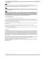
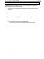
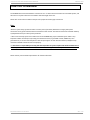
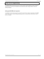
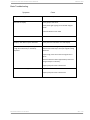
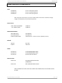
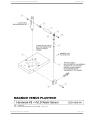
INSTALLATION AND OPERATIONS MANUAL CB-8000-XXX CB-8000-xxx Resin Monitor Installation/Programming Model numbers: CB-8000-APS CB-8000-UPS CB-8000-PAT MAGNUM VENUS PLASTECH APRIL 2013 REV 1.05 PAGE 1 INSTALLATION AND OPERATIONS MANUAL MAGNUM VENUS PLASTECH APRIL 2013 CB-8000-XXX REV 1.05 PAGE 2 INSTALLATION AND OPERATIONS MANUAL CB-8000-XXX TABLE OF CONTENTS CHAPTER 1-Safety and Warning Information ......................................................................................................... 5 Operating Your Polyester System Safely ...................................................................................................................5 1.0 Introduction ...................................................................................................................................................5 1.2 Personal Safety Equipment ............................................................................................................................5 2.0 Material Safety ...............................................................................................................................................5 2.1 Hazards Associated with Laminating Operations ...........................................................................................5 2.2 Catalyst (Methyl Ethyl Ketone Peroxide) .......................................................................................................6 2.3 Clean-Up Solvents and Resin Diluents............................................................................................................6 2.4 Catalyst Diluents ............................................................................................................................................7 2.5 Cured Laminate, Overspray and Laminate Sandings Accumulation...............................................................7 2.7 Toxicity of Chemicals ......................................................................................................................................7 2.8 Treatment of Chemical Injuries ......................................................................................................................7 3.0 Equipment Safety ...........................................................................................................................................8 3.1 Emergency Stop Procedures ..........................................................................................................................8 3.2 Grounding ......................................................................................................................................................8 CHAPTER 2-Introduction ........................................................................................................................................ 9 CHAPTER 3-Installation ........................................................................................................................................ 11 CHAPTER 4-Programming .................................................................................................................................... 13 Setting up the CB-8000-xxx for operation. .............................................................................................................13 LD2006P0 display (large displays) ...........................................................................................................................15 CUB5 display (small display) ...................................................................................................................................17 CHAPTER 5-Calibration ........................................................................................................................................ 19 Calibration ..........................................................................................................................................................19 CHAPTER 6-OPTIONS/PARTS ................................................................................................................................ 21 UNITS ......................................................................................................................................................................21 DISPLAY UNITS ........................................................................................................................................................21 RESIN SENSOR MOUNTS .........................................................................................................................................21 SENSORS .................................................................................................................................................................21 CABLES ....................................................................................................................................................................21 RESET BUTTONS ......................................................................................................................................................21 CHAPTER 7-DRAWINGS ........................................................................................................................................ 23 CHAPTER 8-Revsion History ................................................................................................................................... 1 Terms & Conditions of Sale .................................................................................................................................... 3 MAGNUM VENUS PLASTECH APRIL 2013 REV 1.05 PAGE 3 INSTALLATION AND OPERATIONS MANUAL MAGNUM VENUS PLASTECH APRIL 2013 CB-8000-XXX REV 1.05 PAGE 4 INSTALLATION AND OPERATIONS MANUAL CB-8000-XXX CHAPTER 1-Safety and Warning Information Operating Your Polyester System Safely 1.0 Introduction The manufacturer accepts no liability for any consequences resulting from inappropriate, negligent or incorrect installation or adjustment of the optional operating parameters of the equipment. The contents of this guide are believed to be correct at the time of printing. In the interests of a commitment to a policy of continuous development and improvement, the manufacturer reserves the right to change the specification of the product or its performance, or the contents of the guide, without notice. All rights reserved. No parts of this guide may be reproduced or transmitted in any form or by any means, electrical or mechanical including photocopying, recording or by an information storage or retrieval system, without permission in writing from the publisher. Any tool, if used improperly, can be dangerous. Safety is ultimately the responsibility of those using the tool. In like manner, safe operation of polyester processes is the responsibility of those who use such processes and those who operate the equipment. This manual outlines procedures to be followed in conducting polyester operations safety. This system has been specifically designed for use of Polyester Resin, Gel-Coat, and Methyl Ethyl Ketone Peroxides (MEKP) applications. Other formulations or blends considered for use in this equipment is strictly prohibited without the expressed consent by Magnum Venus Plastech Inc. Magnum Venus Plastech cannot eliminate every danger nor foresee every circumstance that might cause an injury during equipment operation. Some risks, such as the high pressure liquid stream that exits the spray tip, are inherent to the nature of the machine operation and are necessary to the process in order to manufacture the end-product. For this reason, ALL personnel involved in polyester operations should read and understand the Safety Manual. It is very important for the safety of employees involved in the operation that equipment operators, maintenance and supervisory personnel understand the requirements for safe operation. Each user should examine his own operation, develop his own safety program and be assured that his equipment operators follow correct procedures. Magnum Venus Plastech hopes that this manual is helpful to the user and recommends that the precautions in this manual be included in any such program. Magnum Venus Plastech recommends this Safety Manual remain on your equipment at all times for your personnel safety. In addition to the manual, Magnum Venus Plastech recommends that the user consult the regulations established under the Occupational Safety & Health Act (OSHA), particularly the following sections: 1910.94 1910.106 1910.107 Pertaining to Ventilation. Pertaining to flammable liquids Pertaining to spray finishing operations, particularly Paragraph (m) Organic Peroxides and Dual Component Coatings. Other standards and recognized authorities to consult are the National Fire Protection Association (NFPA) bulletins as follows: NFPA No.33 Chapter 14, Organic Peroxides and Dual Component Materials NFPA No.63 Dust Explosion Prevention NFPA No.70 National Electrical Code NFPA No.77 Static Electricity NFPA No.91 Blower and Exhaust System NFPA No.654 Plastics Industry Dust Hazards Type of Fire Extinguishing equipment recommended: Fire Extinguisher – code ABC, rating number 4a60bc. Extinguishing Media – Foam, Carbon Dioxide, Dry Chemical, Water Fog. Copies of the above bulletins are available, at a nominal charge from: National Fire Protection Association 470 Atlantic Avenue Boston, MA 02210 Research Report No.11 of the American Insurance Association deal with “Fire, Explosion and Health Hazards of Organic Peroxides”. It is published by: American Insurance Association 85 John Street New York, NY 10038 Local codes and authorities also have standards to be followed in the operation of your spraying equipment. Your insurance carrier will be helpful in answering questions that arise in your development of safe procedures. 1.2 Personal Safety Equipment Magnum Venus Plastech recommends the following Personal Safety Equipment for conducting safe operations of the Polyester Systems: Magnum Venus Plastech recommends that the user consult the state and local regulations established for all Safety equipment listed. 2.0 Material Safety 2.1 Hazards Associated with Laminating Operations Major hazards which should be guarded against in polyester/epoxy/urethane laminating operations are those associated with: Flammability and explosion dangers of the catalyst/activators/hardeners normally used The flammability dangers of clean-up solvents sometimes used (Magnum Venus Plastech recommends that clean-up solvents be non-flammable), and of resin diluents used, such as styrene. Flammability dangers of catalyst diluents, if used. (Magnum Venus Plastech recommends that catalyst not be diluted) Flammability dangers of the uncured liquid resins. Combustibility dangers of the cured laminate, accumulations of over spray, and laminate sandings. The toxicity dangers of all the chemicals used in laminating operations with respect to ingestion, inhalation and skin and eye hazards. MAGNUM VENUS PLASTECH APRIL 2013 REV 1.05 PAGE 5 INSTALLATION AND OPERATIONS MANUAL CB-8000-XXX 2.2 Catalyst (Methyl Ethyl Ketone Peroxide) MEKP is among the more hazardous materials found in commercial channels. The safe handling of the “unstable (reactive)” chemicals presents a definite challenge to the plastics industry. The highly reactive property which makes MEKP valuable to the plastics industry in producing the curing reaction of polyester resins also produces the hazards which require great care and caution in its storage, transportation, handling, processing and disposal. MEKP is a single chemical. Various polymeric forms may exist which are more or less hazardous with respect to each other. These differences may arise not only from different molecular structures (all are, nevertheless, called “MEKP”) and from possible trace impurities left from the manufacture of the chemicals, but may also arise by contamination of MEKP with other materials in its storage or use. Even a small amount of contamination with acetone, for instance, may produce an extremely shock-sensitive and explosive compound. Contamination with promoters or materials containing promoters, such as laminate sandings, or with any readily oxidizing material, such as brass or iron, will cause exothermic “redox” reactions which can become explosive in nature. Heat applied to MEKP, or heat build-up from contamination reactions can cause it to reach what is called its Self-Accelerating Decomposition Temperature (SADT). Researchers have reported measuring pressure rates-of-rise well in excess of 100,000 psi per second when certain MEKP’s reach their SADT. (For comparison, the highest pressure rate-of-rise listed in NFPA Bulletin NO.68, “Explosion Venting”, is 12,000 psi per second for an explosion of 12% acetylene and air. The maximum value listed for a hydrogen explosion is 10,000 psi per second. Some forms of MEKP, if allowed to reach their SADT, will burst even an open topped container. This suggests that it is not possible to design a relief valve to vent this order of magnitude of pressure rate-of-rise. The user should be aware that any closed container, be it a pressure vessel, surge chamber, or pressure accumulator, could explode under certain conditions. There is no engineering substitute for care by the user in handling organic peroxide catalysts. If, at any time, the pressure relieve valve on top of the catalyst tank should vent, the area should be evacuated at once and the fire department called. The venting could be the first indication of a heat, and therefore, pressure build-up that could eventually lead to an explosion. Moreover, if a catalyst tank is sufficiently full when the pressure relief valve vents, some catalyst may spray out, which could cause eye injury. For this reason, and many others, anyone whose job puts them in an area where this vented spray might go, should always wear full eye protection even when laminating operations are not taking place. Safety in handling MEKP depends to a great extent on employee education, proper safety instructions and safe use of the chemicals and equipment. Workers should be thoroughly informed of the hazards that may result from improper handling of MEKP, especially in regards to contamination, heat, friction and impact. They should be thoroughly instructed regarding the proper action to be taken in the storage, use and disposal of MEKP and other hazardous materials used in the laminating operation. In addition, users should make every effort to: Store MEKP in a cool, dry place in original containers away from direct sunlight and away from other chemicals. Keep MEKP away from heat, sparks and open flames. Prevent contamination of MEKP with other materials, including polyester over spray and sandings, polymerization accelerators and promoters, brass, aluminum and non-stainless steels. Never add MEKP to anything that is hot, since explosive decomposition may result. Avoid contact with skin, eyes and clothing. Protective equipment should be worn at all times. During clean-up of spilled MEKP, personal safety equipment, gloves and eye protection must be worn. Firefighting equipment should be at hand and ready. Avoid spillage, which can heat up to the point of self-ignition. Repair any leaks discovered in the catalyst system immediately, and clean up the leaked catalyst at once in accordance with the catalyst manufacturer’s instructions. Use only original equipment or equivalent parts from Magnum Venus Plastech in the catalyst system (i.e.: hoses, fitting, etc.) because a dangerous chemical reaction may result between substituted parts and MEKP. Catalyst accumulated from the purging of hoses or the measurement of fluid output deliveries should never be returned to the supply tank, such catalyst should be diluted with copious quantities of clean water and disposed of in accordance with the catalyst manufacturer’s instructions. The extent to which the user is successful in accomplishing these ends and any additional recommendations by the catalyst manufacturer determines largely the safety that will be present in his operation. 2.3 Clean-Up Solvents and Resin Diluents WARNING A hazardous situation may be present in your pressurized fluid system! Hydrocarbon Solvents can cause an explosion when used with aluminum or galvanized components in a closed (pressurized) fluid system (pump, heaters, filters, valves, spray guns, tanks, etc.). The explosion could cause serious injury, death and/or substantial property damage. Cleaning agents, coatings, paints, etc. may contain Halogenated Hydrocarbon Solvents. Some Magnum Venus Plastech spray equipment includes aluminum or galvanized components and will be affected by Halogenated Hydrocarbon Solvents. There are three key elements to the Halogenated Hydrocarbon (HHC) solvent hazard: The presence of HHC solvents. 1,1,1 – Trichloroethane and Methylene Chloride are the most common of these solvents. However, other HHC solvents are suspect if used; either as part of paint or adhesives formulation, or for clean-up flushing. Aluminum or Galvanized Parts. Most handling equipment contains these elements. In contact with these metals, HHC solvents could generate a corrosive reaction of a catalytic nature. Equipment capable of withstanding pressure. When HHC solvent contact aluminum or galvanized parts inside a closed container such as a pump, spray gun, or fluid handling system, the chemical reaction can, over time, result in a build-up of heat and pressure, which can reach explosive proportions. When all three elements are present, the result can be an extremely violent explosion. The reaction can be sustained with very little aluminum or galvanized metal; any amount of aluminum is too much. The reaction is unpredictable. Prior use of an HHC solvent without incident (corrosion or explosion) does NOT mean that such use is safe. These solvents can be dangerous alone (as a clean-up or flushing agent) or when used as a component or a coating material. There is no known inhibitor that is effective under all circumstances. Furthermore, the mixing of HHC solvents with other materials or solvents, such as MEKP, alcohol, and toluene, may render the inhibitors ineffective. The use of reclaimed solvents is particularly hazardous. Reclaimers may not add any inhibitors. Also, the possible presence of water in reclaimed solvents could feed the reaction. Anodized or other oxide coatings cannot be relied upon to prevent the explosive reaction. Such coatings can be worn, cracked, scratched, or too thin to prevent contact. There is no known way to make oxide coatings or to employ aluminum alloys, which will safely prevent the chemical reaction under all circumstances. Several solvent suppliers have recently begun promoting HHC solvents for use in coating systems. The increasing use of HHC solvents is increasing the risk. Because of their exemption from many State Implementation Plans as Volatile Organic Compounds (VOC’s), their low flammability hazard, and their not being classified as toxic or carcinogenic substances, HHC solvents are very desirable in many respects. WARNING: Do not use Halogenated Hydrocarbon solvents in pressurized fluid systems having aluminum or galvanized wetted parts. NOTE: Magnum Venus Plastech is aware of NO stabilizers available to prevent Halogenated Hydrocarbon solvents from reaction under all conditions with aluminum components in closed fluid system. TAKE IMMEDIATE ACTION… Halogenated Hydrocarbon solvents are dangerous when used with aluminum components in a closed fluid system. MAGNUM VENUS PLASTECH APRIL 2013 REV 1.05 PAGE 6 INSTALLATION AND OPERATIONS MANUAL CB-8000-XXX Consult your material supplier to determine whether your solvent or coating contains Halogenated Hydrocarbon Solvents. Magnum Venus Plastech recommends that you contact your solvent supplier regarding the best non-flammable clean-up solvent with the heat toxicity for your application. If you find it necessary to use flammable solvents, they must be kept in approved, electrically grounded containers. Bulk solvent should be stored in a well-ventilated, separate building, 50 feet away from your main plant. You should allow only enough solvent for one day’s use in your laminating area. “NO SMOKING” signs must be posted and observed in all areas of storage or where solvents and other flammable materials are used. Adequate ventilation (as covered in OSHA Section 1910.94 and NFPA No.91) is important wherever solvents are stored or used, to minimize, confine and exhaust the solvent vapors. Solvents should be handled in accordance with OSHA Section 1910.106 and 1910.107. 2.4 Catalyst Diluents Magnum Venus Plastech spray-up and gel-coat systems currently produced are designed so that catalyst diluents are not required. Magnum Venus Plastech, therefore, recommends that diluents not be used. This avoids the possible contamination which could lead to an explosion due to the handling and mixing of MEKP and dilettante. In addition, it eliminates any problems from the dilettante being contaminated through rust particles in drums, poor quality control on the part of the diluents suppliers, or any other reason. If, however, diluents are absolutely required, contact your catalyst supplier and follow his instructions explicitly. Preferable, the supplier should premix the catalyst to prevent possible “on the job” contamination while mixing. WARNING If diluents are not used, it should be remembered that catalyst spillage, gun, hose and packing leaks are potentially more hazardous, since each drop contains a higher concentration of catalyst, and therefore will react quicker with over spray and the leak. 2.5 Cured Laminate, Overspray and Laminate Sandings Accumulation Remove all accumulations of overspray, FRP sandings, etc. from the building as they occur. If this waste is allowed to build up, spillage of catalyst is more likely to start a fire, in addition, the fire would burn hotter and longer. Floor coverings, if used, should be non-combustible. Spilled or leaked catalyst may cause a fire if it comes in contact with an FRP product, over-sprayed chop or resin, FRP sandings or any other material with MEKP. To prevent this spillage and leakage, you should: Maintain your Magnum Venus Plastech System. Check the gun several times daily for catalyst and resin packing or valve leaks. REPAIR ALL LEAKS IMMEDIATELY. Never leave the gun hanging over, or lying inside the mold. A catalyst leak in this situation would certainly damage the part, possibly the mold, and may cause a fire. Inspect resin and catalyst hoses daily for wear or stress at the entry and exits of the boom sections and at the hose and fittings. Replace if wear or weakness is evident or suspected. Arrange the hoses and fiberglass roving guides so that the fiberglass strands DO NOT rub against any of the hoses at any point. If allowed to rub, the hose will be cut through, causing a hazardous leakage of material which could increase the danger of fire. Also, the material may spew onto personnel in the area. 2.7 Toxicity of Chemicals Magnum Venus Plastech recommends that you consult OSHA Sections 1910.94, 1910.106, 1910.107 and NFPA No.33, Chapter 14, and NFPA No.91. Contact your chemical supplier(s) and determine the toxicity of the various chemicals used as well as the best methods to prevent injury, irritation and danger to personnel. Also determine the best methods of first aid treatment for each chemical used in your plant. 2.8 Treatment of Chemical Injuries Great care should be used in handling the chemicals (resins, catalyst and solvents) used in polyester systems. Such chemicals should be treated as if they hurt your skin and eyes and as if they are poison to your body. For this reason, Magnum Venus Plastech recommends the use of protective clothing and eye wear in using polyester systems. However, users should be prepared in the event of such an injury. Precautions include: Know precisely what chemicals you are using and obtain information from your chemical supplier on what to do in the event the chemical gets onto your skin or into the eyes, or is swallowed. Keep this information together and easily available so that it may be used by those administering first aid or treating the injured person. Be sure the information from your chemical supplier includes instructions on how to treat any toxic effects the chemicals have. WARNING Contact your doctor immediately in the event of any injury and give him the information you have collected. If your information includes first aid instructions, administer first aid immediately while you are contacting your doctor. Fast treatment of the outer skin and eyes that contact such chemicals generally includes immediate and thorough washing of the exposed skin and immediate and continuous flushing of the eyes with lots of clean water for at least 15 minutes or more. These general instructions of first aid treatment, however, may be incorrect for some chemicals; that is why you must know the chemicals and treatment before an accident occurs. Treatment for swallowing a chemical frequently depends upon the nature of the chemical. NOTE: Refer to your System User Manual for complete and detailed operating instructions and service information. MAGNUM VENUS PLASTECH APRIL 2013 REV 1.05 PAGE 7 INSTALLATION AND OPERATIONS MANUAL CB-8000-XXX 3.0 Equipment Safety WARNING Magnum Venus Plastech suggest that personal safety equipment such as EYE GOGGLES, GLOVES, EAR PROTECTION, and RESPIRATORS be worn when servicing or operating this equipment. Ear protection should be worn when operating a fiberglass chopper to protect against hearing loss since noise levels can be as high as 116 dB (decibels). This equipment should only be operated or serviced by technically trained personnel! WARNING Never place fingers, hands, or any body part near or directly in front of the spray gun fluid tip. The force of the liquid as it exits the spray tip can cause serious injury by shooting liquid through the skin. NEVER LOOK DIRECTLY INTO THE GUN SPRAY TIP OR POINT THE GUN AT OR NEAR ANOTHER PERSON. (TREAT THE GUN AS IF IT WERE A LOADED PISTOL.) WARNING NEVER USE HARD MATERIALS SUCH AS WIRE, PINS, ETC., TO CLEAR A PLUGGED GUN. HARD MATERIALS CAN CAUSE PERMANENT DAMAGE. DAB WITH A BRISTLE BRUSH, BLOW BACKWARDS WITH AIR UNTIL CLEAR WHILE WEARING A PROTECTIVE EYE SHIELD. REPEAT AS MANY TIMES AS NECESSARY. DO NOT PERFORM ANY MAINTENANCE OR REPAIRS UNTIL YOU HAVE FOLLOWED THE PRECAUTIONS STATED ABOVE. IF YOU, AS AN EQUIPMENT OPERATOR OR SUPERVISOR, DO NOT FEEL THAT YOU HAVE BEEN ADEQUATELY TRAINED OR INSTRUCTED AND THAT YOU LACK THE TECHNICAL KNOWLEDGE TO OPERATE OR PERFORM MAINTENANCE ON A PIECE OF MAGNUM VENUS PLASTECH EQUIPMENT, PLEASE CALL MAGNUM VENUS PLASTECH BEFORE OPERATING OR PERFORMING MAINTENANCE ON THE EQUIPMENT. IF YOU HAVE ANY QUESTIONS REGARDING THE ABOVE PRECAUTIONS OR ANY SERVICE OR OPERATION PRECEDURES, CALL YOUR MAGNUM VENUS PLASTECH DISTRIBUTOR OR MAGNUM VENUS PLASTECH. 3.1 Emergency Stop Procedures The following steps should be followed in order to stop the machinery in an emergency situation 1. The ball valve located where the air enters the power head of the resin pump, should be moved to the “OFF” or closed position. To do this, simply rotate the lever on the ball valve 90 degrees. Doing this will cause all the system air to bleed out of the system in a matter of a few seconds, making the system incapable of operating NOTE: Step 2 is a precautionary step and should be followed whenever the above mentioned ball valve is activated to the stop mode. Failure to do so, can damage the regulators and components on reactivating to the “ON” position. 2. Turn all system regulators to the “OFF” position (counter-clockwise) position NOTE: Verify that the Catalyst relief line, located on the catalyst manifold, and the resin return line, located on the resin filter, are secured relieving catalyst and resin fluid pressure. 3. Catalyst pressure in the catalyst pump can be eliminated by rotating the ball valve on the catalyst manifold 90 degrees to the “open” or “on” position. Note: The “open” or “on” position is when the ball valve handle is parallel (in line) with the ball valve body. The “closed” or “off” position is when the ball valve handle is perpendicular (across) the ball valve body. 4. Resin pressure in the resin pump can be eliminated by rotating the ball valve on the resin filter 90 degrees to the “open” or “on” position. Place a container under the ball valve to catch any resin that is ejected out of the valve. 3.2 Grounding Grounding an object means providing an adequate path for the flow of the electrical charge from the object to the ground. An adequate path is one that permits charge to flow from the object fast enough that it will not accumulate to the extent that a spark can be formed. It is not possible to define exactly what will be an adequate path under all conditions since it depends on many variables. In any event, the grounding means should have the lowest possible electrical resistance. Grounding straps should be installed on all loose conductive objects in the spraying area. This includes material containers and equipment. Magnum Venus Plastech recommends grounding straps be made of AWG No.18 stranded wire as a minimum and the larger wire be used where possible. NFPA Bulletin No77 states that the electrical resistance of such a leakage path may be as low as 1 meg ohm (10 ohms) but that resistance as high as 10,000 meg ohms will produce an adequate leakage path in some cases. Whenever flammable or combustible liquids are transferred from one container to another, or from one container to the equipment, both containers or container and equipment shall be effectively bonded and grounded to dissipate static electricity. For further information, see National Fire Protection Association ( NFPA) 77, titled “Recommended Practice on Static Electrical”. Refer especially to section 7-7 titled “Spray Application of Flammable and Combustible Materials”. Check with local codes and authorities for other specific standards that might apply to your application. NOTICE: All statements, information and data given herein are believed to be accurate and reliable but are presented without guaranty, warranty or responsibility of any kind express or implied. The user should not assume that all safety measures are indicated or that other measures are not required. DANGER: Contaminated catalyst may cause Fire or Explosion. Before working on the catalyst pump or catalyst accumulator, wash hands and tools thoroughly. Be sure work area is free of dirt, grease or resin. Clean catalyst system components with clean water only. DANGER: Eye, skin and respiration hazard. The Catalyst, MEKP, may cause blindness, skin irritation or breathing difficulty. Keep hands away from face. Keep food and drink away from work area. WARNING: Please refer MAGNUM VENUS PLASTECH APRIL 2013 REV 1.05 PAGE 8 INSTALLATION AND OPERATIONS MANUAL CB-8000-XXX CHAPTER 2-Introduction The CB-8000-xxx Resin Monitor is designed to help operators achieve resin weight targets. The unit has triple displays with external resets on the two large LED readouts. The unit utilizes an electro-mechanical sensor (either magnetic or proximity) to keep track of fractional pump strokes. Display #1 is used to track certain areas of the part being fabricated, coupled with a remote reset the operator can quickly zero the counter at any time. Display #2 is used to total the resin usage for the entire part. This can be reset locally at the panel via pushbutton. Optionally this can also be configured for a glass counter as an option Display #3 (inside panel) is used to keep track of total resin usage for a period of time. This can be reset inside the panel and can be locked out except for authorized personnel. o Note: If the glass counter option is enabled, this display only keeps track of resin total. The CB-8000-xxx comes standard with a 50 foot remote reset and 25 foot sensor line. Extra lengths are available on request. MAGNUM VENUS PLASTECH APRIL 2013 REV 1.05 PAGE 9 INSTALLATION AND OPERATIONS MANUAL MAGNUM VENUS PLASTECH APRIL 2013 CB-8000-XXX REV 1.05 PAGE 10 INSTALLATION AND OPERATIONS MANUAL CB-8000-XXX CHAPTER 3-Installation The CB-8000-XXX comes with hardware to mount unit to a 2” column which is standard on most MVP systems, and will mount to any flat surface that is suitable to hold the weight of the unit. Please refer to the reference label on the panel for proper electrical supply connections. Note: *Because of the variety of electrical codes in various parts of the world, MVP does not supply main power connections to any of the material monitors mentioned in this manual. The electrical connection should be made by a qualified electrician per codes of local jurisdiction. **Due to the sensitivity of the sensor cables used on the CB-8000-XXX, proper installation of the cables is very important. Cables must be kept as far away from electrical sources (ungrounded conduit, PWM drives, tach generators etc.) as to not create interference with the input signals. In some extreme instances, EMI filters may need to be installed to make the unit work properly. ***The end user is responsible for ensuring that the end product or system complies with all the relevant laws in the country where it is to be used and that all documentation and general electrical practices are adhered to. Please contact your local MVP representative for further information. MAGNUM VENUS PLASTECH APRIL 2013 REV 1.05 PAGE 11 INSTALLATION AND OPERATIONS MANUAL MAGNUM VENUS PLASTECH APRIL 2013 CB-8000-XXX REV 1.05 PAGE 12 INSTALLATION AND OPERATIONS MANUAL CB-8000-XXX CHAPTER 4-Programming The CB-8000-XXX basic functions are factory set to run out of the box. Only two adjustments need to be made to each panel meter to match up to the displacement of the fluid section that it is being installed on and set the decimal point display. Setting up the CB-8000-xxx for operation. The CB-8000-xxx material monitoring system utilizes Red Lion panel meter as displays. Large displays are LD2006P0 and the smaller display is a CUB5. Utilizing the following instructions, the decimal point and scale factors need to be set in each display. MAGNUM VENUS PLASTECH APRIL 2013 REV 1.05 PAGE 13 INSTALLATION AND OPERATIONS MANUAL MAGNUM VENUS PLASTECH APRIL 2013 CB-8000-XXX REV 1.05 PAGE 14 INSTALLATION AND OPERATIONS MANUAL CB-8000-XXX LD2006P0 display (large displays) Using the PAR and SEL keys on the front of the display you will need to navigate to the correct module for programming. Module 1-INP (inputs) is the only one that needs to be modified. Once you have entered the module for programming use the following chart to navigate the module. The greyed out parameters are not available. The following is a step by step procedure on how to change the relevant settings. The only two settings that need to be changed are the decimal point and the scale factor. All other settings are to remain at default. Press the PAR key. Display will read Pro or No. Press the SEL key. Display will read 1-INP Press the PAR key. COUNT MODE Display will read INP Ab. Default setting should be Cnt ud. Press the PAR key. COUNTER A DECIMAL POINT*** MAGNUM VENUS PLASTECH APRIL 2013 Display will read A-dPt Decimal point setup. At this point you will have the option to set the decimal point. Press the SEL key if you wish to set the decimal point and use the RST key to set number of decimals. REV 1.05 PAGE 15 INSTALLATION AND OPERATIONS MANUAL Press the PAR key.*** COUNTER A SCALE FACTOR CB-8000-XXX Display will read A-ScF. Scale Factor entry. At this point you will have the option to set the scale factor for calibration. Press the SEL key if you wish to set the scale factor. Press the SEL key to adjust the number and use the RST key to move from number to number. Please see Chapter 5-Calibration section for setting this number. Press the PAR key. COUNTER A RESET ACTION Display will read A-rST. Default setting should be ZEro. Press the PAR key. COUNTER A COUNT DIRECTION Display will read A-dir. Default setting should be NOr. Press the PAR key. COUNTER A COUNT LOAD VALUE Display will read Cnt-Ld. Default setting should be 50.00. This setting has no bearing on this programming. Press the PAR key. COUNTER B BATCH COUNT ENABLE Display will read b-bAt. Default setting should be NO. Press the PAR key. COUNTER RESET AT POWER-UP Display will read r P-UP. Default setting should be NO. Press the PAR key. USER INPUT FUNCTION Display will read Usr-INP. Default setting should be rESET. Press the PAR key. Display will read Pro or No. Press the PAR key. This will exit programming mode. *** Note: MVP recommends no more than 2 decimal points be used. MAGNUM VENUS PLASTECH APRIL 2013 REV 1.05 PAGE 16 INSTALLATION AND OPERATIONS MANUAL CB-8000-XXX CUB5 display (small display) Using the SEL and RST keys on the front of the display you will need to navigate to the correct module for programming. Module 1-INPUT (inputs) is the only one that needs to be modified. Once you have entered the module for programming use the following chart to navigate the module. The greyed out parameters are not available. The following is a step by step procedure on how to change the relevant settings. The only two settings that need to be changed are the decimal point and the scale factor. All other settings are to remain at default. Note: The small display should never have an R on the left hand side. This means that it is set for rate reading. Pushing the SEL key will toggle from rate to count. Press and hold the SEL key until meter enters program mode. Display will read INPUt Press the RST key. Display will read INPUT A-b Press the SEL key. COUNT MODE Display will read INP Ab. Default setting should be Cnt ud. Press the SEL key. COUNTER A DECIMAL POINT*** MAGNUM VENUS PLASTECH APRIL 2013 Display will read CntA dP Decimal point setup. At this point you will have the option to set the decimal point. Press the RST key if you wish to set the decimal point. REV 1.05 PAGE 17 INSTALLATION AND OPERATIONS MANUAL Press the SEL key COUNTER A SCALE FACTOR CB-8000-XXX Display will read CntA ScF. Scale Factor entry. At this point you will have the option to set the scale factor for calibration. Press the RST key if you wish to set the scale factor. Press the RST key to adjust the number and use the SEL key to move from number to number. Once you have set the scale factor, press and hold the SEL key to accept the number. Press the SEL key. COUNTER A RESET ACTION Display will read CntA-rST. Default setting should be to ZEro. Press the SEL key. COUNTER A COUNT DIRECTION Display will read CntA-dir. Default setting should be NOr. Press the SEL key. COUNTER A COUNT LOAD VALUE Display will read CntA-Ld. Default setting should be 50.00. This setting has no bearing on this programming. Press the SEL key. COUNTER B BATCH COUNT ENABLE Display will read CntB-bAt. Default setting should be NO. Press the SEL key. COUNTER RESET AT POWER-UP Display will read RST P-UP. Default setting should be NO. Press the SEL key. USER INPUT FUNCTION Display will read User-INP. Default setting should be rESET. *** Note: MVP recommends no more than 2 decimal points be used. MAGNUM VENUS PLASTECH APRIL 2013 REV 1.05 PAGE 18 INSTALLATION AND OPERATIONS MANUAL CB-8000-XXX CHAPTER 5-Calibration Calibration Navigate to the scale factor on all displays and set to 1.0000. Exit programming mode. Reset all counters. Using a container, dispense material. If volume is to be used the container must have volumetric marks on it. Once the container has been filled, record what the display reading is. Using the net weight or volume from the container divide it by the monitor display. This will be the adjusted scale factor that needs to be entered into all of the displays. Example: Dispensed material is 12.50 lbs. Monitor displayed weight is 8.56 lbs. 12.50/8.56= 1.46 1.460 should be entered into the scale factor for each monitor. Once this is done the display will read the correct weight once you exit out of program mode. Verify by resetting all counters and dispensing into bucket and checking vs. the displayed value. If the reading has a large variance, repeat the above steps. If the variance is small, manipulate the scale factor until the display is correct. MAGNUM VENUS PLASTECH APRIL 2013 REV 1.05 PAGE 19 INSTALLATION AND OPERATIONS MANUAL CB-8000-XXX Basic Troubleshooting. Symptom Cause No power when power switch is turned on. Check fuse inside panel No totals on display Verify proper scale factor Verify ensor light is going on and off with magnet reads Check for broken sensor cable Remote reset will not work Check for broken sensor cable Displays read different upon calibration Verify the same scale factor is in each display Scale factor has to be adjusted way out of range from initial entry or constantly adjusted Double counts from magnet. Inspect proximity switch LED to ensure that only 1 count per magnet is being detected. Inspect mag rod to ensure that all magnets are in place. Head of switch should be approximately 4mm from magnet. Adjust as necessary. Inspect pumps for wear or feed issues Test shots not matching counter Adjust scale factor Inspect pumps for wear or feed issues. MAGNUM VENUS PLASTECH APRIL 2013 REV 1.05 PAGE 20 INSTALLATION AND OPERATIONS MANUAL CB-8000-XXX CHAPTER 6-OPTIONS/PARTS UNITS CB-8000-APS CB-8000-UPS CB-8000-PAT For use on APS pump systems. For use on UPS pump systems. For use on PAT pump systems. Note: All systems come with 25’ resin sensor cable and 50’ remote reset as standard. If longer lengths are needed they must be ordered separately. DISPLAY UNITS 2.250” DISPLAY (LD2006P0) .541” DISPLAY (CUB5) E-CRM-103 E-CRM-102 RESIN SENSOR MOUNTS APS PUMP SYSTES UPS PUMP SYSTEM PATRIOT PUMP SYSTEM CSD-1000-APS CSD-1000-UPS E-SENS-100-CB *** Note, must have E-MLM to connect) SENSORS APS/UPS PATRIOT APS-1025 E-SEN-102 CB-CABLE-25 CB-CABLE-50 CB-CABLE-SP 25’ EXTENSION/SENSOR CABLE 50’ EXTENSION/SENSOR CABLE SPLITTER FOR DUAL RESETS CABLES RESET BUTTONS CB-RST-100 GUN MOUNTED RESET BUTTON (RUBBERIZED) CB-RST-200 WALL MOUNTED RESET BUTTON NOTE: IN ORDER TO USE THE CB-RST-200 TO RESET THE LOWER DISPLAY THE CB-CABLE-SP MUST BE USED. MAGNUM VENUS PLASTECH APRIL 2013 REV 1.05 PAGE 21 INSTALLATION AND OPERATIONS MANUAL MAGNUM VENUS PLASTECH APRIL 2013 CB-8000-XXX REV 1.05 PAGE 22 INSTALLATION AND OPERATIONS MANUAL CB-8000-XXX CHAPTER 7-DRAWINGS MAGNUM VENUS PLASTECH APRIL 2013 REV 1.05 PAGE 23 INSTALLATION AND OPERATIONS MANUAL MAGNUM VENUS PLASTECH APRIL 2013 CB-8000-XXX REV 1.05 PAGE 24 INSTALLATION AND OPERATIONS MANUAL MAGNUM VENUS PLASTECH APRIL 2013 CB-8000-XXX REV 1.05 PAGE 25 INSTALLATION AND OPERATIONS MANUAL MAGNUM VENUS PLASTECH APRIL 2013 CB-8000-XXX REV 1.05 PAGE 26 INSTALLATION AND OPERATIONS MANUAL MAGNUM VENUS PLASTECH APRIL 2013 CB-8000-XXX REV 1.05 PAGE 27 INSTALLATION AND OPERATIONS MANUAL MAGNUM VENUS PLASTECH APRIL 2013 CB-8000-XXX REV 1.05 PAGE 28 INSTALLATION AND OPERATIONS MANUAL MAGNUM VENUS PLASTECH APRIL 2013 CB-8000-XXX REV 1.05 PAGE 29 INSTALLATION AND OPERATIONS MANUAL MAGNUM VENUS PLASTECH APRIL 2013 CB-8000-XXX REV 1.05 PAGE 30 INSTALLATION AND OPERATIONS MANUAL MAGNUM VENUS PLASTECH APRIL 2013 CB-8000-XXX REV 1.05 PAGE 31 INSTALLATION AND OPERATIONS MANUAL CB-8000-XXX 100.1 ---- 24VCOM 30 (245.1) FU1 2.00A CUSTOMER SUPPLIED: 100/230 1PH 50/60H FLA .45A @ 120 FLA .25A @ 220 L101 L102 L201 L201 +24V 31 (245.1) 150.1 --- GND -18AWG -- -14AWG --- L201 L102 GND 105.1 155.1 -- GROUND BLOCK (ON PANEL BACKPAN) -- -- -- -- -- 110.1 160.1 S1 -L103 -L102 L201 -- -- -- -- -- -- 115.1 165.1 -- -GND TBA3 -- -L201 RED LION -L103 L103 L201 TBA2 LD2006P0 -- TBA1 -120.1 -- TBB1 TBB2 TBB3 INPA I/COM INPB TBB4 +EXC TBB5 USR TBB6 COM 170.1 TBB7 COM -- -- -- -- -- -30 -- -- 125.1 175.1 -- -- 31 -- -- -- -- -- -- GND TBA3 130.1 -- L201 RED LION L103 180.1 TBA2 LD2006P0 L103 L201 -- TBA1 --- -TBB1 TBB2 TBB3 INPA I/COM INPB TBB4 +EXC TBB5 USR TBB6 COM TBB7 COM -- -- -- 135.1 185.1 -- 30 -- 30 -- -- --- -31 31 -- 140.1 190.1 -- -- -- -- -- -- -- -- 145.1 195.1 -- -- -- -- -- -- -- -- DRAWN: DATE: BJS 062012 APPROVED: WIRING SCHEMATIC HIGH VOLTAGE DATE: CHECKED: DATE: TITLE: ISSUED: 1 PART DASH NO. PROPERTY OF MAGNUM VENUS PLASTECH This print, or drawing is the property of MVP and is considered confidential or proprietary information. It is not to be copied, reproduced, used or disclosed in whole or in part, unless in reference to contracts or proposals of this company. Nothing disclosed herein which is not publicy available may be used without prior written permission of MVP and all rights herein reserved. MAGNUM VENUS PLASTECH APRIL 2013 REV 1.05 PAGE 1 NEXT FINAL QTY REQD PER ASSY NEXT ASSY FINAL ASSY APPLICATION SHEET: SCALE: 2 OF 5 CB-8000-XXX SYSTEM: SIZE: DRAWING No: REV: A INSTALLATION AND OPERATIONS MANUAL MAGNUM VENUS PLASTECH APRIL 2013 CB-8000-XXX REV 1.05 PAGE 2 INSTALLATION AND OPERATIONS MANUAL CB-8000-XXX 24VCOM 30 (150.1) 200.1 +24V 31 (150.1) 250.1 -- -- -- -- -- -- -- -- 205.1 255.1 -- -- -- -31 -- -- -- -- 210.1 260.1 -- -I/COM USR INPB INA -- -- --- -31 +24VDC RED LION CUB5 COM 30 30 -- 215.1 265.1 -- -- -- -- -- -- -- -- 220.1 270.1 -- -- -- -- -- -- -- -- 225.1 275.1 -- -- -- -- -- -- -- -- 230.1 280.1 -- -- -- -- -- -- -- -- 235.1 285.1 -- -- -- -- -- -- -- -- 240.1 290.1 -- -- -- -- -- -- -- -- 245.1 295.1 -- -- -- -- -- -- -- -- DRAWN: DATE: BJS 062012 APPROVED: WIRING SCHEMATIC LOW VOLTAGE DATE: CHECKED: DATE: TITLE: ISSUED: 1 PART DASH NO. PROPERTY OF MAGNUM VENUS PLASTECH This print, or drawing is the property of MVP and is considered confidential or proprietary information. It is not to be copied, reproduced, used or disclosed in whole or in part, unless in reference to contracts or proposals of this company. Nothing disclosed herein which is not publicy available may be used without prior written permission of MVP and all rights herein reserved. MAGNUM VENUS PLASTECH APRIL 2013 REV 1.05 PAGE 3 NEXT FINAL QTY REQD PER ASSY NEXT ASSY FINAL ASSY APPLICATION SHEET: SCALE: 3 OF 5 CB-8000-XXX SYSTEM: SIZE: DRAWING No: REV: A INSTALLATION AND OPERATIONS MANUAL MAGNUM VENUS PLASTECH APRIL 2013 CB-8000-XXX REV 1.05 PAGE 4 INSTALLATION AND OPERATIONS MANUAL CB-8000-XXX RED LION DISPLAY LD2006P0 UPPER 900.1 -- -IN00 -SHLD (WHT) 30 (BLU) 31 (BRN) --- 950.1 (GRY) N.C. IN00 (BLK) TBB1 INPUT A 30 30 IN00 --- 30 -TBB2 INPUT COM 905.1 955.1 -- -- -- TBB3 INPUT B -- -- -- -- -TBB4 910.1 -- +EXC 31 (BLK) 31 (BRN) -(GRY) N.C. IN02 (BLU) IN02 -TBB5 -- -- -- REMOVE JUMPER FROM TERMINAL BLOCKS (IN00/IN01) TO USE SECOND DISPLAY AS GLASS COUNTER ---- TBB6 COM IN00 MAG. SRC. HI FREQ. 3 LO FREQ. SNK. 4 SRC. HI FREQ. 5 LO FREQ. RESET/USER INPUT SNK. 6 SRC. PWR UP RESET DISABLE 7 ENABLE INPUT B DIRECTION CONTROL 8 INTENSITY ADJUST LOGIC 1 MAG. SNK. 2 SRC. HI FREQ. 3 LO FREQ. 965.1 -- IN01 --- -- -- 920.1 970.1 RED LION DISPLAY LD2006P0 LOWER --- --- IN01 -SHLD (WHT) 30 (BLU) 31 (BRN) -(GRY) TBB1 INPUT A 30 30 --975.1 N.C. IN00 (BLK) IN01 30 -- TBB2 INPUT COM -- --- -- -TBB3 INPUT B -- -- 930.1 -- 2 -30 915.1 925.1 1 SNK. 960.1 -- IN02 LOGIC 980.1 PB 02 RESET LOWER DISPLAY TBB4 +EXC -- -- SNK. 4 SRC. HI FREQ. 5 LO FREQ. RESET/USER INPUT SNK. 6 SRC. PWR UP RESET DISABLE 7 ENABLE INPUT B DIRECTION CONTROL 8 INTENSITY ADJUST -31 -- IN03 -IN03 IN03 -- TBB5 RESET/USER (DIP SWITCH 5 ON) -- IN03 (WHT) 935.1 -- 985.1 30 -TBB6 COM -- -- -- -- -- -- 940.1 990.1 -- -- -- RED LION DISPLAY CUB5 --- ---- INP COM 945.1 995.1 -- -ON -- USR -- -- -- -- -- 1 2 3 4 DRAWN: DATE: BJS 062012 APPROVED: INP B WIRING SCHEMATIC ONBOARD INPUTS DATE: CHECKED: DATE: TITLE: ISSUED: IN00 1 INP A PROPERTY OF MAGNUM VENUS PLASTECH This print, or drawing is the property of MVP and is considered confidential or proprietary information. It is not to be copied, reproduced, used or disclosed in whole or in part, unless in reference to contracts or proposals of this company. Nothing disclosed herein which is not publicy available may be used without prior written permission of MVP and all rights herein reserved. MAGNUM VENUS PLASTECH APRIL 2013 REV 1.05 PAGE 5 PART DASH NO. NEXT FINAL QTY REQD PER ASSY NEXT ASSY FINAL ASSY APPLICATION SHEET: SCALE: 4 OF 5 CB-8000-XXX SYSTEM: SIZE: DRAWING No: REV: A INSTALLATION AND OPERATIONS MANUAL MAGNUM VENUS PLASTECH APRIL 2013 CB-8000-XXX REV 1.05 PAGE 6 INSTALLATION AND OPERATIONS MANUAL CB-8000-XXX RED LION DISPLAY LD2006P0 UPPER 900.1 -- -IN00 -SHLD (WHT) 30 (BLU) 31 (BRN) --- 950.1 (GRY) N.C. IN00 (BLK) TBB1 INPUT A 30 30 IN00 --- 30 -TBB2 INPUT COM 905.1 955.1 -- -- -- TBB3 INPUT B -- -- -- -- -TBB4 910.1 -- +EXC 31 (BLK) 31 (BRN) -(GRY) N.C. IN02 (BLU) IN02 -TBB5 -- -- -- REMOVE JUMPER FROM TERMINAL BLOCKS (IN00/IN01) TO USE SECOND DISPLAY AS GLASS COUNTER ----- TBB6 -- COM IN00 MAG. SRC. HI FREQ. 3 LO FREQ. SNK. 4 SRC. HI FREQ. 5 LO FREQ. RESET/USER INPUT SNK. 6 SRC. PWR UP RESET DISABLE 7 ENABLE INPUT B DIRECTION CONTROL 8 INTENSITY ADJUST LOGIC 1 MAG. SNK. 2 SRC. HI FREQ. 3 LO FREQ. 965.1 -- IN01 ---- PLACE JUMPER ON TERMINAL BLOCKS (IN02/IN03) TO USE REMOTE RESET ON BOTH DISPLAYS 920.1 970.1 RED LION DISPLAY LD2006P0 LOWER -- --- IN01 -SHLD (WHT) 30 (BLU) 31 (BRN) -(GRY) TBB1 INPUT A 30 30 --975.1 N.C. IN00 (BLK) IN01 30 -- TBB2 INPUT COM -- --- -- -TBB3 INPUT B -- -- 930.1 -- 2 -30 915.1 925.1 1 SNK. 960.1 -- IN02 LOGIC 980.1 PB 02 RESET LOWER DISPLAY TBB4 +EXC -- -- SNK. 4 SRC. HI FREQ. 5 LO FREQ. RESET/USER INPUT SNK. 6 SRC. PWR UP RESET DISABLE 7 ENABLE INPUT B DIRECTION CONTROL 8 INTENSITY ADJUST -31 -- IN03 -IN03 IN03 -- TBB5 RESET/USER (DIP SWITCH 5 ON) -- IN03 (WHT) 935.1 -- 985.1 30 -TBB6 COM -- -- -- -- -- -- 940.1 990.1 -- -- -- RED LION DISPLAY CUB5 --- ---- INP COM 945.1 995.1 -- -ON -- USR -- -- -- -- -- 1 2 3 4 DRAWN: DATE: BJS 021113 APPROVED: INP B WIRING SCHEMATIC ONBOARD INPUTS DATE: CHECKED: DATE: TITLE: ISSUED: IN00 1 INP A PROPERTY OF MAGNUM VENUS PLASTECH This print, or drawing is the property of MVP and is considered confidential or proprietary information. It is not to be copied, reproduced, used or disclosed in whole or in part, unless in reference to contracts or proposals of this company. Nothing disclosed herein which is not publicy available may be used without prior written permission of MVP and all rights herein reserved. MAGNUM VENUS PLASTECH APRIL 2013 REV 1.05 PAGE 7 PART DASH NO. NEXT FINAL QTY REQD PER ASSY NEXT ASSY FINAL ASSY APPLICATION SHEET: SCALE: 4 OF 5 CB-8000-XXX SYSTEM: SIZE: DRAWING No: REV: B INSTALLATION AND OPERATIONS MANUAL MAGNUM VENUS PLASTECH APRIL 2013 CB-8000-XXX REV 1.05 PAGE 8 INSTALLATION AND OPERATIONS MANUAL CB-8000-XXX 3000.1 3050.1 -- -- CB-CABLE-25 -- -- -- -E-MLC-100 -3005.1 -- E-FLC-100 (2) SHLD (3) 30 (BLK) RESIN SENSOR NOT CONNECTED (2) 30 (BLK) (3) 3055.1 (1) 31 (RED) (4) IN00 (WHT) 31 (RED) (1) IN00 (WHT) (4) -- -- -- -- -- 3010.1 3060.1 -- -- -- -E-MLC-100 NOT CONNECTED (2) 30 (BLK) (3) (1) 31 (RED) (4) IN00 (WHT) 3065.1 -- 31 (RED) (1) IN00 (WHT) (4) 4 -3070.1 -- -- -- -- CB-CABLE-50 -- -- -- -E-MLC-100 3025.1 E-FLC-100 (2) SHLD (3) 30 (BLK) SINGLE REMOTE RESET NOT CONNECTED (2) 30 (BLK) (3) (1) 31 (RED) (4) IN00 (WHT) 31 (RED) (1) IN00 (WHT) (4) 3075.1 (1) 31 -- (3) IN02 -3080.1 -- -- CB-CABLE-SP -- -- -- -E-FLC-100 -(3) 30 (BLK) 30 (BLK) (3) (1) 31 (RED) 31 (RED) (1) 3035.1 --- -- (1) 31 (3) IN02 (1) 31 (3) IN03 CB-RST-100 PB 01 RESET UPPER DISPLAY (OPTIONAL) DUAL REMOTE RESET --E-FLC-100 (2) 30 (BLK) 30 (BLK) (3) (4) 31 (RED) 31 (RED) (1) --3090.1 -- -- -- -- -- 3045.1 E-MLC-100 3085.1 E-MLC-100 3040.1 -- CB-RST-100 PB 01 RESET UPPER DISPLAY -- -- -- E-MLC-100 -- 3030.1 -- 3 -- -- -- 1 -- 3020.1 -- GLASS COUNT SENSOR E-FLC-100 (2) SHLD (3) 30 (BLK) (OPTIONAL) GLASS SENSOR -- -- 4 -- -- -- 3 -- CB-CABLE-50 -- -- 1 -- -- 3015.1 RESIN COUNT SENSOR -- CB-RST-200 PB03 RESET LOWER DISPLAY E-MLC-100 -- SHRINK WRAP BOTH WIRES 4.00" COMING OUT OF CONECTOR -3095.1 -- -- -- -- -- -- -- -- DRAWN: DATE: BJS 062012 APPROVED: WIRING SCHEMATIC CABLING DATE: CHECKED: DATE: TITLE: ISSUED: 1 PART DASH NO. PROPERTY OF MAGNUM VENUS PLASTECH This print, or drawing is the property of MVP and is considered confidential or proprietary information. It is not to be copied, reproduced, used or disclosed in whole or in part, unless in reference to contracts or proposals of this company. Nothing disclosed herein which is not publicy available may be used without prior written permission of MVP and all rights herein reserved. MAGNUM VENUS PLASTECH APRIL 2013 REV 1.05 PAGE 9 NEXT FINAL QTY REQD PER ASSY NEXT ASSY FINAL ASSY APPLICATION SHEET: SCALE: 5 OF 5 CB-8000-XXX SYSTEM: SIZE: DRAWING No: REV: A INSTALLATION AND OPERATIONS MANUAL MAGNUM VENUS PLASTECH APRIL 2013 CB-8000-XXX REV 1.05 PAGE 10 INSTALLATION AND OPERATIONS MANUAL CB-8000-XXX CHAPTER 8-Revsion History Date Revision Note 06-20-12 08-19-12 01-21-13 REV 1.00 REV 1.02 REV 1.04 Document created. Updated drawings, updated programming sequence. Updated installation notes Updated Red Lion unit programming Updated calibration Updated sensor drawings 04-29-13 02-19-14 REV 1.04 REV 1.04 Added display part numbers Added PAT sensor MAGNUM VENUS PLASTECH APRIL 2013 REV 1.05 PAGE 1 INSTALLATION AND OPERATIONS MANUAL MAGNUM VENUS PLASTECH APRIL 2013 CB-8000-XXX REV 1.05 PAGE 2 INSTALLATION AND OPERATIONS MANUAL CB-8000-XXX Terms & Conditions of Sale 1. ACCEPTANCE: Acceptance of any purchase order from a customer or potential customer (“Buyer”) is subject to credit approval by GSSC, Inc. (“Seller”), acceptance of the purchase order by Seller and, when applicable, any manufacturer, vendor, or other third party that provides goods to Seller for resale to Buyer (“Vendor”). If Seller, in its sole discretion, determines that Buyer's credit becomes unsatisfactory or it has reasonable grounds for insecurity, Seller reserves the right, upon notice to Buyer, to demand adequate assurance of due performance from Buyer and/or terminate any purchase order with no liability to Seller. BY REQUESTING A QUOTE FROM SELLER, ACCEPTING AN INVOICE FROM SELLER, OR PRESENTING A PURCHASE ORDER TO SELLER, BUYER CONFIRMS THAT THESE TERMS & CONDITIONS SHALL GOVERN ALL PURCHASES OF PRODUCTS OR MATERIALS PROVIDED TO BUYER BY SELLER (“GOODS”). GOODS SOLD BY SELLER ARE EXPRESSLY SUBJECT TO THE TERMS AND CONDITIONS SET FORTH HEREIN AND ANY DIFFERENT OR ADDITIONAL TERMS OR CONDITIONS SET FORTH IN A PURCHASE ORDER OR SIMILAR COMMUNICATION RECEIVED FROM BUYER ARE OBJECTED TO AND SHALL NOT BE BINDING UPON SELLER UNLESS SPECIFICALLY AGREED TO IN WRITING BY AN AUTHORIZED CORPORATE OFFICER OF SELLER.NO SELLER EMPLOYEE OR AGENT HAS THE AUTHORITY TO MODIFY THESE TERMS & CONDITIONS VERBALLY. SELLER OBJECTS TO AND REJECTS ANY TERMS BETWEEN BUYER AND ANY OTHER PARTY, AND NO SUCH TERMS, INCLUDING BUT NOT LIMITED TO ANY GOVERNMENT REGULATIONS OR “FLOWDOWN” TERMS, SHALL BE A PART OF OR INCORPORATED INTO ANY PURCHASE ORDER FROM BUYER TO SELLER, UNLESS AGREED TO IN WRITING BY AN AUTHORIZED REPRESENTATIVE OF SELLER. 2. PRICES AND TAXES: Buyer agrees to pay the prices quoted by Seller or listed on any related invoice, and is responsible for additional applicable shipping and handling charges, taxes, duties, and charges for import and export licenses and certificates. All prices quoted by Seller are subject to change without notice. Seller will generally collect applicable taxes along with the purchase price unless Buyer submits a valid tax exemption certificate, and indicates which Goods are covered by it. Prices on special-order Goods may be subject to change before shipment. In order to be corrected any discrepancies in pricing and/or quantities on invoices must be reported by Buyer within thirty (30) days of the invoice date. 3. PAYMENT: Payment terms are 30 days net from the invoice date or upon such other terms approved by Seller in writing. Retainage shall not apply, and Buyer shall not hold back any retainage from Seller, even if retainage is part of any contract between Buyer and any other party. Payment is not contingent on Buyer’s ability to collect or obtain funds from any other party. Credit card sales are billed at the time of purchase. Buyer expressly represents it is solvent at the time it places any purchase order with Seller. Seller, in its sole discretion, may determine that Buyer’s financial condition requires full or partial payment prior to manufacture or shipment. If Buyer fails to make any payment when due, Seller reserves the right to suspend performance. Buyer agrees to pay a charge on all amounts past due at the rate of 1 ½% per month (18% per year) or the maximum lawful rate, whichever is less. In the event of non-payment, Buyer agrees to pay Seller’s reasonable attorney fees and court costs, if any, incurred by Seller to collect payment, and all applicable interest charges. Seller may apply payments to any outstanding invoices unless Buyer provides specific payment direction. 4. TITLE AND RISK OF LOSS OR DAMAGE: As to Goods delivered directly by Seller, title passes upon delivery at the place Buyer receives possession; and, thereafter, all risk of loss or damage shall be on Buyer. All other sales are F.O.B., point of shipment, and Buyer takes title and assumes responsibility for risk of loss or damage at the point of shipment for such sales. Claims for Goods damaged in transit are Buyer’s sole responsibility when not delivered directly by Seller. 5. QUOTATIONS: All quotations expire thirty (30) days from the date of the quotation unless otherwise noted on the quotation. This time limit applies even if Buyer uses the quotation to submit a job or project bid to any other party. 6. ASSIGNMENT: The Buyer’s rights and responsibilities under any purchase order or these Terms & Conditions shall not be assigned by Buyer without the express written consent of the Seller. 7. RETURN OF GOODS: Permission to return items must be requested and granted in advance. No credit will be given if items are returned prior to requesting and receiving permission. Subject to the foregoing, Seller shall accept returns of Goods for any reason for a period of thirty (30) days following shipment for exchange or refund of the purchase price; provided, that such Goods must be unused and are subject to a 15% restocking charge, which may be increased or decreased, in the Seller’s sole discretion, depending on the reason for such return. Any Goods which were special ordered by Buyer are may not be returned, and any such Goods which are returned are subject to a restocking/cancellation fee of 100% of the cost of the Goods. Goods shall be deemed accepted by Buyer (and cannot thereafter be returned), if Buyer fails to object to the Goods within thirty (30) days after the Goods are received by Buyer. 8. CANCELLATION: The Buyer may cancel any purchase order prior to shipment of the Goods by mutual agreement of the parties and upon payment to Seller of reasonable and proper cancellation charges. 9. TERMINATION: Seller may terminate the whole or any part of any purchase order if there is a material breach of these Terms & Conditions. In the event of any such breach, the Seller will provide Buyer with written notice of the nature of the breach and the Seller’s intention to terminate for default. In the event Buyer does not cure such failure within ten (10) days of such notice, Seller may, by written notice, terminate the purchase order; provided, that Buyer shall continue its performance to the extent not terminated. 10. CHANGE IN BUYER’S FINANCIAL CONDITION: Seller reserves the right to cancel any order or to require full or partial payment in advance without liability to Seller in the event of: (i) insolvency of the Buyer; (ii) the filing of voluntary petition in bankruptcy by Buyer; (iii) the appointment of a Receiver or Trustee for the Buyer; (iv) the execution by Buyer of an assignment for benefit of creditors; or (v) past due payment on previous shipments to Buyer by Seller. Seller reserves the right to cancel Buyers credit at any time for any reason. 11. INTERPRETATION RESPONSIBILITY; PRODUCT USE AND SAFETY: Seller does not guarantee that the Goods it sells conform to any plans and specifications or intended use. When plans and specifications are involved, Buyer is solely responsible for verifying Seller’s interpretations of such plans and specifications, and it is Buyer’s sole responsibility to assure that Seller’s Goods will be acceptable for any specific job. When Seller offers substitute Goods on any proposal, Buyer is solely responsible for confirming their acceptability. 12. DELIVERY: Shipping dates given in advance of actual shipment are approximate and not guaranteed. All contract dates and timelines begin upon receipt by Seller of a purchase order, Buyer’s acceptance of these Terms & Conditions, and the payment of any required down payment. MAGNUM VENUS PLASTECH APRIL 2013 REV 1.05 PAGE 3 INSTALLATION AND OPERATIONS MANUAL CB-8000-XXX Corporate HQ/Mfg. th 5148 113 Ave. Clearwater, FL 33760 USA Ph: (727) 573-2955 Fax: (727) 571-3636 E-mail: [email protected] MAGNUM VENUS PLASTECH APRIL 2013 Manufacturing/Sales 1862 Ives Ave. Kent, WA 98032 USA Ph: (253) 854-2660 Fax: (253) 854-1666 Web: www.mvpind.com REV 1.05 PAGE 1