1
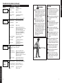
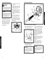
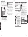
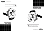
SHINDAIWA OWNER’S/
OPERATOR'S MANUAL
AH231 ARTICULATED
HEDGE TRIMMER
Shindaiwa Inc.
P.O. Box 2810
Tualatin, Oregon 97062
Telephone: 503 692-3070
FAX:
503 692-6696
www.shindaiwa.com
Shindaiwa Kogyo Co., Ltd.
Head Office: 6-2-11 Ozuka
Nishi, Asaminami-ku
Hiroshima, 731-3167, Japan
Telephone: 81-82-849-2220
FAX:
81-82-849-2481
WARNING!
Minimize the risk of injury to
yourself and others! Read this
manual and familiarize yourself
with the contents. Always wear
eye and hearing protection
when operating this unit.
䊚2002 Shindaiwa, Inc.
Part Number 63848-94010
Printed in Japan
Rev. 2/02
Specifications subject to change without notice.
Part Number 63848-94010
Rev. 2/02
Contents
Attention Statements
PAGE
Attention Statements ........................... 1
Introduction ......................................... 2
Throughout this manual are special
attention statements.
DANGER!
Safety Precautions ............................... 2
Operating Precautions ........................ 5
Operating the Trimmer ...................... 7
Specifications ....................................... 8
A statement preceded by the
triangular attention symbol and
the word “DANGER” indicates an
imminently hazardous situation
which, if not avoided, WILL result
in death or serious injury!
Product Description ............................ 9
Powerhead Installation ..................... 10
WARNING!
Assembly and Adjustment ................ 11
Adjusting the Cutter Assembly ........ 13
Engine Fuel ........................................ 15
Starting the Engine ........................... 16
Stopping the Engine .......................... 18
Adjusting Engine Idle ....................... 19
Maintenance ...................................... 20
Cutter Blade Adjustment .................. 25
Long Term Storage ........................... 26
Troubleshooting Guide .................... 27
Emission System Warranty .............. 31
A statement preceded by the
triangular attention symbol and the
word “WARNING” indicates a
potentially hazardous situation
which, if not avoided, COULD
result in death or serious injury.
CAUTION!
A statement preceded by the word
“CAUTION” contains information
that should be acted upon to avoid
damage to the unit.
IMPORTANT!
A statement preceded by the word
“IMPORTANT” is one that possesses
special significance.
NOTE
A statement preceded by the word
“NOTE” contains information that is
handy to know and may make your
job easier.
1
Introduction
SAFETY
The Shindaiwa AH231 Articulatied
Hedge Trimmer is designed and built
to deliver superior performance and
reliability without compromise to
quality, comfort, safety or durability.
Shindaiwa’s high-performance
engines represent the leading edge of
2-cycle engine technology, delivering
exceptionally high power with remarkably low displacement and weight. As
an owner/operator, you’ll soon
discover for yourself why Shindaiwa is
simply in a class by itself!
Safety Precautions
DANGER!
THE ARTICULATED HEDGE
TRIMMER IS NOT INSULATED
AGAINST ELECTRICAL SHOCK!
Approaching or contacting
electrical lines with the trimmer
could cause death or serious
injury. Keep the trimmer at least
33 feet (10 meters) away from
electrical lines or branches that
contact electrical lines.
IMPORTANT!
The information contained in these
instructions describes units available at
the time of publication. While every
attempt has been made to provide the
latest information about your
Shindaiwa product, there may be some
differences between your AH231 and
what is described here. Shindaiwa Inc.
reserves the right to make changes to
products without prior notice and
without obligation to make alterations
to units previously manufactured.
The procedures described in this
manual are intended to help you get
the most from your unit as well as to
protect you and others from harm.
These procedures are guidelines for
safe operation under most conditions,
and are not intended to replace any
safety rules and/or laws that may be
in force in your area.
If you have questions regarding
your power tool, or if you do not
understand something in this manual,
your Shindaiwa dealer will be glad to
assist you.
You may also contact Shindaiwa,
Inc. at the address printed on the back
of this Manual.
WARNING!
The engine exhaust from this
product contains chemicals known
to the State of California to cause
cancer, birth defects or other
reproductive harm.
An articulated hedge trimmer has the
potential to do serious damage if
misused, abused or mishandled. To
reduce the risk of injury, you must
maintain control at all times, and
observe all safety precautions during
operation. Never permit a person
without training or instruction to
operate this trimmer!
2
Safety Precautions
SAFETY
Read and follow this
manual, make sure
anyone using the trimmer
does likewise. Failure to
do so could result in
serious personal injury or
machine failure. Keep
this manual for future
reference
Always wear a hard hat to
reduce the risk of head
injuries during operation
of this machine. In
addition, always wear eye
and hearing protection.
Shindaiwa recommends
wearing a face shield as
additional face and eye
protection. Wear non-slip
heavy-duty gloves to
improve your grip on the
trimmer handle. Wear
sturdy footwear with
nonslip soles to provide
good footing. Steel-toed
safety boots are recommended. Wear snugfitting clothes that also
permit freedom of
movement.
Never operate this tool or
any other power equipment if you are tired, ill,
or under the influence of
alcohol, drugs, or any
substance that could
affect your ability or
judgement.
3
Electrical Hazard
50ft
15M
Keep bystanders at least
50 feet (15 meters) away
from the operating
trimmer to reduce the
risk of being struck by
falling objects or thrown
debris.
Danger Falling Debris
Owners Warranty
Responsibilities
As the small off-road engine owner,
you are responsible for the performance of the required maintenance
listed in this owners manual.
Shindaiwa Kogyo Co., Ltd. recommends that you retain all receipts
covering maintenance on your small
off-road engine, but Shindaiwa Kogyo
Co., Ltd. cannot deny warranty solely
for the lack of receipts or for your
failure to ensure the performance of
all scheduled maintenance.
As the small off-road engine owner,
you should be aware, however, that
Shindaiwa Kogyo Co., Ltd. may deny
you warranty coverage if your small
off-road engine or a part has failed due
to abuse, neglect, improper maintenance, or unapproved modifications.
You are responsible for presenting
your small off-road engine to an
authorized Shindaiwa Dealer as soon
as a problem exists. The warranty
repairs should be completed in a
reasonable amount of time, not to
exceed 30 days.
If you have any questions regarding
your warranty rights and responsibilities, you should contact a Shindaiwa
customer service representative at
(503) 692-3070 or your local Shindaiwa
Dealer.
Consequential Damages
In the event that other component
parts of this product are damaged by
the failure of a warranted part,
Shindaiwa Kogyo Co., Ltd. will repair
or replace such component parts at no
charge to you.
What is Not Covered
■ Failures caused by abuse, neglect,
or improper maintenance
procedures.
■ Failures caused by the use of
modified or non-approved parts or
attachments.
This Warranty is Administered by:
Shindaiwa Inc.
11975 S.W. Herman Rd.
Tualatin, OR 97062
(503) 692-3070
32
Emission System Warranty Statement
The California Air Resources Board, the
U.S. Environmental Protection Agency
and Shindaiwa Kogyo Co., Ltd. are
pleased to explain the emission control
system warranty on your new small offroad (non-road) engine.
In California, new small off-road
engines must be designed, built, and
equipped to meet the State’s stringent
anti-smog standards. In other states,
new 1997 and later non-road engines
must meet the Federal EPA’s stringent anti-smog standards. Shindaiwa
Kogyo Co., Ltd. must warrant the
emission control system on your small
off-road engine for the periods of time
listed below, provided there has been
no abuse, neglect, or improper
maintenance of your small off-road
engine.
Your engine emission control
system includes parts such as the
carburetor, the ignition system and, if
equipped, the catalytic converter.
These components are specifically
listed below.
Where a warrantable condition
exists, Shindaiwa Kogyo Co., Ltd. will
repair your small off-road engine at no
cost to you including diagnosis, parts,
and labor.
SAFETY
Your Warranty Rights and
Obligations
Safety Equipment and Labels
Manufacturer’s Warranty
Coverage
When sold within the U.S., this
engine’s emission control system is
warranted for a period of two (2) years
from the date this product is first
delivered to the original retail purchaser.
During the warranty period,
Shindaiwa Kogyo Co., Ltd. will, at
their option, repair or replace any
defective emission-related component
on this engine. During the original
Warranty Period, these Warranty
Rights are automatically transferable
to subsequent owners of this product.
Shaft Safety Label
Cutter Blade
Scabbard
What is Covered by this
Warranty
High Voltage Label
1. Carburetor Internal Components
■ Throttle Valve, Needle, Jet,
Metering Diaphragm
Ignition
Switch
Hand
Guard
2. Ignition System Components
■ Ignition Coil
■ Flywheel Rotor
3. Catalytic Converter (if originally
equipped)
The emission control system for
your particular Shindaiwa engine may
also include certain related hoses and
connectors.
IMPORTANT!
Safety and Operation Information
Labels: Make sure all information
labels are undamaged and readable.
Immediately replace damaged or
missing information labels. New labels
are available from your local authorized Shindaiwa dealer.
Throttle Interlock
Figure 1
31
4
Operating Precautions
Troubleshooting Guide (continued)
SAFETY
WARNING!
Use Good Judgement
■ Always make sure the cutter
attachment is properly
installed and firmly tightened
before operation.
■ Never use a cracked or
warped cutter or cutter bar:
replace it with a serviceable
one and make sure it fits
properly.
■ Before starting the engine,
make sure the cutter is not
contacting anything.
■ Always stop the engine
immediately and check for
damage if you strike a foreign
object or if the unit becomes
tangled. Do not operate with
broken or damaged equipment.
■ When cutting a branch that is
under tension, be alert for
spring-back so that you will
not be struck by the moving
branch.
■ Stop the unit immediately if it
suddenly begins to vibrate or
shake. Inspect for broken,
missing or improperly installed
parts or attachments.
■ Do not operate the articulated
hedge trimmer with the muffler
removed.
■ Make sure there is always good
ventilation when operating the
articulated hedge trimmer.
Fumes from engine exhaust can
cause serious injury or death.
Never run the engine indoors!
■ Make sure there are no missing
or loose fasteners, and that the
stop switch and throttle controls
are working properly.
ADDITIONAL PROBLEMS
Symptom
Excessive
vibration.
Cutter will not
rotate.
Possible Cause
Remedy
Warped or damaged
attachment.
Inspect and replace
attachment as required.
Loose gearcase.
Tighten gearcase securely.
Bent main shaft/worn or
damaged bushings.
Inspect and replace
as necessary.
Shaft not installed
in powerhead or
gearcase.
Inspect and reinstall
as required.
Broken shaft.
Consult your servicing
dealer.
Damaged gearcase.
Consult your servicing
dealer.
■ If a cutter should bind fast in a
cut, shut off the engine immediately. Push the branch or tree to
ease the bind and free the
cutter.
■ Make sure the cutters are
correctly adjusted before
operating the articulated hedge
trimmer (see page 24 for cutter
adjustment procedures). Never
attempt cutter adjustment with
the engine running!
WARNING!
Minimize the Risk of Fire
5
■ ALWAYS inspect the unit for
fuel leaks before each use.
During each refill, check that no
fuel leaks from around the fuel
cap and/or fuel tank. If fuel leaks
are evident, stop using the unit
immediately. Fuel leaks must be
repaired before using the unit.
■ NEVER place flammable material
close to the engine muffler.
■ NEVER run the engine without
the spark arrester screen in place.
30
TROUBLESHOOTING
■ NEVER smoke or light fires
near the unit.
■ ALWAYS stop the engine and
allow it to cool before refueling. Avoid overfilling and wipe
off any fuel that may
have spilled.
■ ALWAYS move the unit to a
place well away from a fuel
storage area or other readily
flammable materials before
starting the engine.
Troubleshooting Guide (continued)
Poor
acceleration.
Engine stops
abruptly.
Possible Cause
Remedy
Clogged air cleaner
element.
Clean the air cleaner
element.
Clogged fuel filter.
Replace the fuel filter.
Carburetor mixture
too lean.
Consult with an authorized
servicing dealer.
Idle speed set too low.
Adjust: 2.750 (Ⳳ250) rpm (min-1)
Switch turned off.
Reset the switch and re-start.
Fuel tank empty.
Refuel.
Clogged fuel filter.
Replace filter.
Water in the fuel.
Drain and refill with fresh, clean
unleaded gasoline with a pump octane
of 87 or higher mixed with
a 2-cycle air cooled mixing oil that
meets or exceeds ISO-L-EGD
and/or JASO FC classified oils at
50:1 gasoline/oil ratio.
Shorted spark plug or
loose terminal.
Clean and replace spark plug,
tighten the terminal.
Ignition failure.
Consult with an authorized
servicing dealer.
Consult with an authorized
servicing dealer.
Piston seizure.
Engine difficult
to shut off.
Ground (stop) wire is
disconnected, or switch
is defective.
Test and replace
as required.
Overheating due to
incorrect spark plug.
Replace the spark plug with a
Champion CJ8 or equivalent spark
plug of the correct heat range.
Adjust the spark plug electrode gap to
0.024-inch (0.6 mm).
Overheated engine.
Idle engine until cool. Refer to
page 20 (overheated engine).
Engine idle too high.
Set idle: 2,750 (Ⳳ250) rpm (min-1)
Broken clutch spring or
worn clutch spring boss.
Replace spring/shoes as
required, check idle speed.
Loose attachment
holder.
Inspect and re-tighten
holder securely.
WARNING!
■ Never transport the articulated
hedge trimmer nor set it down
with the engine running. An
engine that’s running could be
accidently accelerated causing
the blades to oscillate.
■ Make sure the cover is in
place when transporting the
articulated hedge trimmer.
■ When carrying the articulated
hedge trimmer by hand, the
cutter attachment should be
pointing backward with the
cutter blade in the retracted or
transporting position (see
page 13 for articulating
adjustment procedures).
See Figure 2.
TROUBLESHOOTING
29
CAUTION!
■ Always maintain the articulated hedge trimmer according
to this owner’s manual and
follow the recommended
scheduled maintenance.
■ Never modify or disable any of
the hedge trimmer’s safety
devices.
■ Always use genuine
Shindaiwa parts and accessories when repairing or maintaining this unit.
■ Do not make unauthorized
modifications to the articulated
hedge trimmer.
■ Never allow the engine to run
at high RPM without a load.
Doing so could damage the
engine.
■ When transporting the hedge
trimmer in a vehicle, tie it
down securely to prevent fuel
spillage or damage to the unit.
■ Always clear your work area
of trash or hidden debris to
help ensure good footing.
■ Keep the cutters sharp and
properly adjusted.
AH231_02
Cutting
attachment
moves at
engine idle.
SAFETY
ADDITIONAL PROBLEMS
Symptom
Figure 2
■ Keep the articulated hedge
trimmer as clean as possible.
Keep it free of loose vegetation, mud, etc.
6
Operating the Articulated Hedge Trimmer
Troubleshooting Guide (continued)
SAFETY
LOW POWER OUTPUT
What To Check
Always wear a hard hat to reduce
the risk of head injuries during
operation of this unit.
Secure long hair
so it is above
shoulder level.
Wear non-slip heavyduty gloves to improve
your grip on the trimmer
handle. Wear snugfitting clothes that also
permit freedom of
movement. NEVER
wear shorts!
Is the engine
overheating?
Always wear eye and hearing
protection. Shindaiwa recommends
wearing a face shield as additional
face and eye protection.
Always operate with
both hands firmly
gripping the unit.
Shorten trimmer line. Cut at
a slower rate.
Carburetor mixture is
too lean.
Consult with an authorized
servicing dealer.
Improper fuel ratio.
Refill with fresh, clean unleaded
gasoline with a pump octane
of 87 or higher mixed with
a 2-cycle air cooled mixing oil that
meets or exceeds ISO-L-EGD
and/or JASO FC classified oils at
50:1 gasoline/oil ratio.
Fan, fan cover, cylinder
fins dirty or damaged.
AH231_03
Keep bystanders at least 50 feet
(15 meters) away from the
operating trimmer to reduce the
risk of being struck by falling
objects or thrown debris.
Engine is rough
at all speeds.
May also have
black smoke
and/or unburned
fuel at the
exhaust.
AH231_04
Figure 3
Clean, repair or replace
as necessary.
Consult with an authorized
servicing dealer.
Clogged air cleaner
element.
Service the air cleaner.
Loose or damaged
spark plug.
Tighten or replace.
Replace the spark plug with a
Champion CJ8 or equivalent spark
plug of the correct heat range.
Adjust the spark plug electrode gap to
0.024-inch (0.6 mm).
Air leakage or clogged
fuel line.
Repair or replace fuel
filter and/or fuel line.
Water in the fuel.
Refill with fresh, clean unleaded
gasoline with a pump octane
of 87 or higher mixed with
a 2-cycle air cooled mixing oil that
meets or exceeds ISO-L-EGD
and/or JASO FC classified oils at
50:1 gasoline/oil ratio.
Piston seizure.
Faulty carburetor and/
or diaphragm.
Consult with an authorized
servicing dealer.
Consult with an authorized
servicing dealer.
Overheating condition.
See above.
Improper fuel.
Check fuel octane rating;
check for presence of
alcohol in the fuel (pg. 15).
Refuel as necessary.
Carbon deposits in the
combustion chamber.
Consult with an authorized
servicing dealer.
28
TROUBLESHOOTING
Engine is
knocking.
7
Remedy
Operator is overworking
the machine.
Carbon deposits on the
piston or in the muffler.
Keep a proper footing and do not
overreach—maintain your balance
at all times during operation.
Wear sturdy footwear with
nonslip soles to provide good
footing. Steel-toed safety boots
are recommended. Never
operate unit bare-footed.
Possible Cause
Troubleshooting Guide
AH231 Specifications
ENGINE DOES NOT START
What To Check
Consult with an authorized
servicing dealer.
NO
Loose spark plug.
Excess wear on
cylinder, piston, rings.
Tighten and re-test.
Consult with an authorized
servicing dealer.
NO
Fuel incorrect, stale, or
contaminated; mixture
incorrect.
Refill with fresh, clean unleaded
gasoline with a pump octane
of 87 or higher mixed with
a 2-cycle air cooled mixing oil that
meets or exceeds ISO-L-EGD
and/or JASO FC classified oils at
50:1 gasoline/oil ratio
NO
Check for clogged fuel
filter and/or vent.
Clean as required;
restart.
The ignition switch
is in “O” (OFF) position.
Shorted ignition ground.
Faulty ignition unit.
Move switch to “I” (ON)
position and re-start.
Consult with an authorized
servicing dealer.
If the plug is wet, excess
fuel may be in the
cylinder.
Crank the engine with the
plug removed, reinstall the
spark plug, and re-start.
The plug is fouled
or improperly gapped.
Clean and re-gap the spark plug
to 0.024 inch (0.6 mm). Re-start.
Spark Plug
to meet Federal emission requirements.
EPA version ............. Champion CJ8 Category C = 50 hours (Moderate), B = 125
The plug is damaged
internally or of the
wrong size.
Replace the spark plug with a
Champion CJ8 or equivalent spark
plug of the correct heat range.
Adjust the spark plug electrode gap to
0.024-inch (0.6 mm).
Air Filter ........... Nonreversible flocked (Extended).
filter element
Specifications are subject to change without notice.
YES
YES
Does the tank
contain fresh
fuel of the
proper grade?
YES
Is fuel visible
and moving in
the return line
when priming?
YES
Is there spark at NO
the spark plug
wire terminal?
YES
TROUBLESHOOTING
Check the
spark plug.
27
Length (storage or transporting
Starting Method .......................... Recoil
position) ................ 2360mm/93.0 in.
Cooling System ..................... Forced air
Engine Type ............ 2-cycle, air-cooled,
Stopping Method ............... Slide switch
vertical-cylinder
Transmission Type .............. Automatic,
Bore x Stroke .... 32 x 28 mm/1.3 x 1.1"
centrifugal clutch with bevel gear
Displacement ........... 22.5 cc/1.4 cu. in.
Blade Length .............. 567 mm/22.3 in.
Maximum Output ........... 1.1 hp/0.8kW
Cutter Drive ........................... Spur gear
@ 7500 rpm (min-1)
Gear Lubricant .. Lithium-based grease
Fuel/oil ratio ...... 50:1 with ISO-L-EGD
Standard Equipment ..............................
or JASO FC class 2-cycle Mixing Oil
Tool kit containing a spark plug
Shindaiwa ONE is a registered
wrench, 4mm hex wrench, and
JASO FC classified oil and also meets
8 x 10mm spanner
or exceeds ISO-L-EGD performance
Optional Equipment ................ Harness
requirements.
and bracket
Fuel Tank Capacity ...... 670 cc/22.7 oz.
EPA Emission
Carburetor Type .............. Walbro WYL
Compliance Period* ........... Category A
diaphragm type
* The EPA emission compliance referred to
Ignition .............. One-piece, electronic, on the emission compliance label located on
the engine, indicates the number of operating
transistor-controlled
hours for which the engine has been shown
hours (Intermediate) and A = 300 hours
8
DESCRIPTION
Remedy
Faulty recoil starter.
Fluid in the crankcase.
Internal damage.
Does the engine NO
crank?
Good
compression?
Dry Weight ..................... 5.9 kg/13.0 lb. Muffler Type ............... 2-Stage Catalyst
Possible Cause
Product Description
Long Term Storage
Whenever the unit will not be used for
30 days or longer, use the following
procedures to prepare it for storage:
Top Engine
Cover Screw
Air Filter
Assembly
Spark
Plug
DESCRIPTION
Cutter Assembly
Adjustment Lever
Hedge Trimmer
Cutter Assembly
■ Clean external parts thoroughly
and apply a light coating of oil to all
metal surfaces.
CAUTION!
Gasoline stored in the carburetor
for extended periods can cause
hard starting, and could also lead
to increased service and maintenance costs.
■ Drain all the fuel from the fuel tank.
IMPORTANT!
Outer
Tube
AH231_05
Recoil
Starter
Fuel Tank
Cutter Blade
Scabbard
Powerhead Assembly
To remove the remaining fuel from
the fuel lines and carburetor and with
the fuel drained from the fuel tank.
Hand
Guard
Handle
Grip
Stop Switch
Hedge Trimmer
Cutter Assembly
Latch Lock
AH231_07
AH231_06
Fuel Tank Guard
Latch
Release
Gearcase
All stored fuels should be stabilized
with a fuel stabilizer such as
STA-BIL™ , if
oil with fuel
stabilizer is not used.
Cutter Bar and
Cutter Blades
■ Remove the spark plug and pour
about 1/4 ounce of 2-cycle mixing
oil into the cylinder through the
spark plug hole. Slowly pull the
recoil starter 2 or 3 times so oil will
evenly coat the interior of the
engine. Reinstall the spark plug.
■ Before storing the unit, repair or
replace any worn or damaged parts.
2. Start and run the engine until stops
running.
■ Remove the air cleaner element
from the carburetor and clean it
thoroughly with soap and water.
Let dry and reassemble the
element.
3. Repeat steps 1 and 2 until the
engine will no longer start.
■ Store the unit in a clean, dust-free
area.
1. Prime the primer bulb until no
more fuel is passing through.
Figure 4
Prior To Assembly
■ Engine assembly
■ Outer tube/cutter assembly
IMPORTANT!
The terms “left”, “left-hand”, and “LH”;
“right”, “right-hand”, and “RH”; “front”
and “rear” refer to directions as
viewed by the operator during normal
operation.
MAINTENANCE
Using Figure 4 as a guide, familiarize
yourself with the Shindaiwa AH231
articulated hedge trimmer and its
various components. Understanding
your unit helps ensure top performance, longer service life, and safer
operation.
Before assembling, make sure you
have all the components required for a
complete unit:
WARNING!
Do not make unauthorized
modifications or alterations to your
articulated hedge trimmer or its
components.
■ Kit with this manual and tool kit for
routine maintenance.
■ Cutter blade scabbard
Carefully inspect all components for
damage.
9
26
Cutter Blade Adjustment
WARNING!
The cutter blades are very sharp!
Always wear gloves when working
around the cutter assembly.
CAUTION!
Cutter performance of your unit
depends in great measure on cutter
blade clearance. Properly adjusted
blades will oscillate freely yet help
prevent binding of cut material
between blades. Adjust blades as
follows (Figure 32):
Spark
Plug
2. Tighten each blade shoulder bolt
firmly, and then loosen the shoulder bolts 1/4 to 1/2 turn.
Main
Shaft
Outer Tube
3. Working from the gearcase end,
lock each bolt in place by firmly
tightening its locknut while
preventing the shoulder bolt from
turning.
Ignition
Switch
When shoulder bolt adjustment is
correct, there should be a gap of
0.25–0.50 mm between the cutter
blades and the flat washers, and the
flat washer beneath each bolt head
should turn freely.
Grip
Tube
Clamp
Clamp Screw
Throttle Lever
Locknut
Figure 5
Guide Bar
Connect the Outer Tube to the Powerhead.
AH231_38
Cutter Blades
Figure 32
Shoulder
Bolt
Washer
(should turn
freely)
1. Place the powerhead on a clean, flat 3. Add some moly-type EP grease to
surface, spark plug facing up.
splines at the end of the main shaft.
2. Use the 4mm hex wrench to loosen
Tube Clamp
Hex
Wrench
4. Slide the outer tube into the tube
clamp until the tube bottoms. If
installation is difficult, rotate the
outer tube or main shaft slightly
until you feel the mainshaft splines
engage with the powerhead.
See Figure 5.
5. Position the outer tube so that the
ignition switch is facing up and the
throttle lever is facing down.
See Figure 5.
AH231_09
MAINTENANCE
ASSEMBLY
Operating the trimmer with worn or
improperly adjusted cutters will
reduce cutter performance and
may also damage your unit.
Powerhead Installation
1. Loosen all blade locknuts at least
one full turn.
Shim Washer
Figure 6
the tube clamp screw. Verify that
the D-shaped shim washer is
positioned as shown in Figure 6.
6. Slide the outer tube into the
powerhead until the throttle grip
just contacts the tube clamp.
7. Tighten the clamp screw firmly.
CAUTION!
CAUTION!
Do not remove the D-shaped shim
washer! The shim washer prevents damage from overtightening
the tube clamp screw.
25
Do not force the shaft tube into the
powerhead! Excessive force can
damage the shaft tube and
mainshaft.
10
Assembly: AH231
135-hour Maintnenace
Disconnect the spark plug boot
and loosen the three engine cover
screws (top screw is captive)
1. Remove the spark plug boot.
2. Loosen the three cylinder cover
screws, and then lift off the cylinder
cover.
Top
Engine
Cover
Screw
AH231_10
Lower Engine
Cover Screws
WARNING!
5. Remove the rear muffler shield bolt
and, while noting the orientation of
parts, separate the muffler shield.
6. Remove the spark arrester screen
and clean with a stiff bristle brush.
7. Gently tap the muffler on a wood
surface to dislodge any loose
carbon.
1. Remove the spark plug boot.
8. Inspect the cylinder exhaust port
for carbon buildup.
2. Loosen the two 4 mm engine cover
screws (located at the top of the
recoil housing).
9. Reassemble the muffler in the
reverse order of disassembly.
3. Loosen the 5 mm engine top cover
screw (the screw is captive) and lift
the cover from the engine.
If you note excessive carbon buildup,
consult your servicing dealer.
Rear Muffler
Shield
Figure 7
Install the black wire between the
two cable adjusters.
4. Remove the two 5 mm muffler
screws. Remove the lower muffler
screw, then lift the muffler assembly from the engine.
Every 135 hours of operation,
remove and clean the muffler.
Never operate the unit with a
damaged or missing muffler or
spark arrester! Operating with
missing or damaged exhaust
components is a fire hazard and
could also damage your hearing.
ASSEMBLY
Allen
Wrench
Remove the Cylinder Cover.
IMPORTANT!
Spark
Arrester
Screen
Connect the
throttle cable
Ignition
Ground
Lead
Forward
Muffler
Shield
5 mm Muffler
Screws
MAINTENANCE
23139
Cable
Adjuster
AH231_12
AH231_11
Figure 8
Figure 9
2. Install the black wire between the
two cable adjuster nuts as shown in
Figure 8.
11
Catalyst
Muffler
Lower Muffler
Screw
Figure 31
Connect the Throttle Cable.
1. Loop the ribbed cable tube to the
top left side of the engine.
Rear
Muffler
Shield Bolt
3. Connect the S-shaped end of the
throttle cable to the throttle lever
on top of the carburetor.
See Figure 9.
24
50-Hour Maintenance
Assembly; AH231
Every 50 hours of operation
(more frequently in dusty or
dirty conditions):
■ Remove and clean the cylinder
cover and clean dirt and debris
from the cylinder cooling fins.
Black Wire
AH231_35
■ Lubricate the gearcase. To
perform this operation, first remove
the gearcase from the outer tube as
follows (Figure 28.):
Outer Tube
Figure 29
Servicing the fuel filter
Spark Plug
Wire
CAUTION!
Make sure you do not pierce the
fuel line with the end of the
hooked wire. The line is delicate
and can be damaged easily.
AH231_34
Figure 28
Gearcase
Index Bolt
CAUTION!
Do not remove the D-shaped shim
washer from the gearcase clamp!
The shim washer prevents
damage from overtightening the
tube clamp screw.
MAINTENANCE
a. Loosen the gearcase clamp bolt.
b. Remove the index bolt from the
gearcase.
■ Use a hooked wire to extract the
fuel filter from inside the fuel tank
(Figure 30). Inspect the fuel filter
element. If it shows signs of
contamination from debris, replace
it with a genuine Shindaiwa replacement fuel filter element. Before
reinstalling the filter, inspect the
fuel line. If you discover damage or
deterioration, the unit should be
removed from service until it can be
inspected by a Shindaiwa-trained
service technician.
c. Slide the gearcase out of the tube.
Using a grease gun, pump lithiumbase grease (about 10 grams) into
the grease fitting on the gearcase
until you see old grease being
purged from the gearcase (Figure
29). Purged grease will be visible in
the outer tube cavity. Clean up
excess grease, then reassemble the
gearcase onto the outer tube. Make
sure the index bolt fits into the hole
on the outer tube. Securely tighten
both bolts.
23
ASSEMBLY
Gearcase
Clamp Bolt
Gearcase
Grease
Fitting
Hooked
Wire
AH231_13
Black Wire
Connector
Figure 10
Assemble and Adjust the Throttle Cable.
1. Insert the throttle-cable housing
3. Using finger pressure only, connect
into the notch on the fan cover, and
the black switch wire from the
clamp the black wire’s connector
cable tube to the red ignition wire
between the fan cover and the cable
on the powerhead. Wire routing
outer adjuster nut as shown.
must be as shown in the illustration
with the black wire located over the
2. Tighten the two throttle cable
spark plug wire.
adjuster nuts.
IMPORTANT!
Adjust and tighten the cable nuts to
allow approximately 1/4-inch freeplay
at the throttle trigger.
4. Reinstall the cylinder cover and
tighten the three cover screws.
5. Reinstall the spark plug boot.
CAUTION!
Wiring routing must not interfere
with throttle operation.
AH231_36
Filter Element
Figure 30
12
Adjusting the Hedge Trimmer Cutter Assembly
WARNING!
■ The cutter blades are very
sharp. Do not grasp the
blades with your hands. Do
not brush the blades against
your body.
■ Never run the engine nor
operate the articulated hedge
trimmer when the cutter
assembly is in the storage/
transport position.
2. With the index finger of your left
hand, press the latch release. With
your left thumb, press the latch
lock. See Figure 12.
Latch Release
10-Hour Maintenance
CAUTION!
CAUTION!
Do not operate the unit if the air
cleaner or element is damaged, or
if the element is wet.
Before removing the spark plug,
clean the area around the plug to
prevent dirt and debris from getting
into the engine’s internal parts.
Every 10 hours of operation,
(more frequently in dusty or
dirty conditions):
Remove the air cleaner element from
the air cleaner housing and clean it
thoroughly with soap and water. Let it
dry before reinstalling the element.
See Figure 25.
AH231_15
IMPORTANT!
OPERATION
1. With your right hand, grasp the
handle, located immediately
behind the hand guard. With your
left hand, grip the adjustment lever
on the cutter assembly.
See Figure 11.
Adjustment
Lever
Every 10 to 15 hours
of operation:
■ Remove and clean the spark plug.
See Figure 26. Adjust the spark
plug electrode gap to 0.024-inch
(0.6 mm). If the plug must be
replaced, use only: Champion CJ8
or equivalent type spark plug of
correct heat range.
Unscrew
Fastener
Always use gloves when working near
the cutter assembly.
Position the hedge trimmer on a flat,
level surface with the engine resting
on the fuel tank guard. Make sure the
scabbard is in place on the blade.
10/15-Hour Maintenance
Clean the spark
plug and check
the gap at the
electrode.
AH231_16
Latch Lock
AH231_31
Figure 12
3. While holding the latch lock down,
pivot the cutter assembly using the
adjustment lever until it is straight
with the outer tube (pivot 180° ).
See Figure 13.
0.024 inch
(0.6 mm)
AH231_32
Figure 26
AH231_30
Remove and
clean the
element
Adjustment
Lever
■ Lubricate the cutter assembly
gearbox by pumping one or two
strokes of lithium-base grease into
the grease fitting using a lever-type
grease gun. See Figure 27.
CAUTION!
AH231_14
AH231_17
Figure 13
Figure 11
IMPORTANT!
The latch lock provides an interlock to
help prevent inadvertent depression of
the latch release.
13
MAINTENANCE
Overlubricating can cause the
gearbox to operate sluggishly and
can cause grease to leak out.
4. Release the latch lock and the latch
release. Make sure the latch lock
and the latch release return
securely to a locking position.
5. Remove the scabbard from the
cutter blade. The engine now may
be started (refer to page 16 for
procedures).
Gearbox
Grease
Fitting
Figure 25
AH231_33
Figure 27
22
Daily Maintenance
Prior to each work day, perform the
following:
■ Remove all dirt and debris from the
engine, check the cooling fins and
air cleaner for clogging, and clean
as necessary. See Figure 24.
Keep cooling
fins clean
AH231_29
Keep air
passages
clean
WARNING!
Always wear gloves when working
around the cutter assembly.
■ Clean any debris or dirt from the
hedge trimmer cutter blades.
Lubricate the blades before use and
after refueling. Check the cutters for
damage or incorrect adjustment.
■ Check for loose or missing screws or
components. Make sure the cutter
attachment is securely fastened.
■ Check the entire unit for leaking
fuel or grease.
■ Make sure nuts, bolts, and screws
(except carburetor adjusting
screws) are tight.
Adjusting the Hedge Trimmer
Cutter Assembly for Desired
Cutting Angles
WARNING!
WARNING!
Do not touch the cutter blades
when the engine is running. The
blades can oscillate even if the
engine is idling.
270°
Various blade
positions
possible
120°
1. With the engine off, install the
scabbard onto the blade.
2. Using the procedures described on
the previous page, rotate the cutter
assembly so it is parallel to the
tube. Make sure the latch lock and
the latch release return securely to
a locking position. See Figure 15.
The cutter assembly
can be adjusted to 10
different positions
ranging from 120° to
270° from the outer
tube as shown in
Figure 14. Refer to the
steps on the previous
page for adjustment
procedures. Always
AH231_18make sure the lock
latch is securely
locked after each
adjustment.
OPERATION
MAINTENANCE
Never run the engine when
adjusting the cutter assembly to
the storage position.
3. Make sure the scabbard is in place
on the cutters before storing or
transporting.
Figure 24
■ Carefully remove any accumulations
of dirt or debris from the muffler and
fuel tank. Check cooling air intake
area at base of crankcase. Remove
all debris. Dirt build-up in these areas
can lead to engine overheating, fire,
or premature wear.
Adjusting the Cutter Assembly
for Storage or Transportation
Gearcase rotated to the
storage/transportation position
AH231_18
Figure 15
Figure 14
21
14
General Maintenance
Mixing Fuel
CAUTION!
Some types of gasoline contain
alcohol as an oxygenate. Oxygenated gasoline may cause increased operating temperatures.
Under certain conditions, alcoholbased gasoline may also reduce
the lubricating qualities of some 2cycle mixing oils. Never use any
type of gasoline containing more
than 10% alcohol by volume!
Generic oils and some outboard
oils may not be intended for use in
high-performance 2-cycle type
engines, and should never be
used in your Shindaiwa engine.
OPERATION
CAUTION!
This engine is designed to operate
on a 50:1 mixture consisting of
unleaded gasoline and ISO-L-EGD
or JASO FC class 2-cycle mixing oil
only. Use of non-approved mixing
oils in catalyst equipped units can
lead to excessive carbon deposits.
WARNING!
Minimize the risk of fire!
■ Stop engine before refueling.
■ Always allow the Articulated
Hedge Trimmer to cool before
refueling!
■ Wipe all spilled fuel and move
the Articulated Hedge Trimmer at least 10 feet (3 meters)
from the fueling point before
restarting!
■ Never start or operate this unit
if there is a fuel leak!
■ Never start or operate this unit
if the carburetor, fuel lines,
fuel tank and/or fuel tank cap
are damaged.
■ Never smoke or light any fires
near the trimmer or fuel!
■ Never place any flammable
material near the engine
muffler!
■ Never operate the engine
without the muffler and spark
arrester in place and properly
functioning!
Filling the Fuel Tank
1. Place the Articulated Hedge
Trimmer on a flat, level surface.
2. Clear any dirt or other debris from
around the fuel filler cap.
3. Remove the fuel cap, and fill the
fuel tank with clean, fresh fuel
mixture.
Examples of 50:1 mixing quantities
4.
Install
and firmly tighten the
■ 1 gallon of gasoline to 2.6 oz. mixing oil
fuel cap.
■ 5 litres of gasoline to 100 ml. mixing oil
IMPORTANT!
Oil is a registered JASO FC
Mix only enough fuel for your immedi- classified oil and also meets or
ate needs! If fuel must be stored
exceeds ISO-L-EGD performance
longer than 30 days and
oil with requirements. Shindaiwa One is
fuel stabilizer is not used, it should
recommended for use in all Shindaiwa
first be treated with a fuel stabilizer
low emissions egines. Shindaiwa one
such as StaBil™.
also includes a fuel stabilizer.
15
MAINTENANCE, REPLACEMENT,
OR REPAIR OF EMISSION CONTROL DEVICES AND SYSTEM MAY
BE PERFORMED BY ANY REPAIR
ESTABLISHMENT OR INDIVIDUAL.
HOWEVER, WARRANTY REPAIRS
MUST BE PERFORMED BY A
DEALER OR SERVICE CENTER
AUTHORIZED BY SHINDAIWA
KOGYO, LTD. AND USE OF PARTS
THAT ARE NOT EQUIVALENT IN
PERFORMANCE AND DURABILITY
TO AUTHORIZED PARTS MAY
IMPAIR THE EFFECTIVENESS OF
THE EMISSION CONTROL SYSTEM
AND MAY HAVE A BEARING ON
THE OUTCOME OF THE WARRANTY CLAIM.
Muffler
WARNING!
Operating the engine without a
muffler or with a muffler that is
damaged or improperly installed
can increase engine noise sufficiently to cause hearing loss.
This unit must never be operated with a
faulty or missing spark arrestor or
muffler. Make sure the muffler is well
secured and in good condition. A worn
or damaged muffler is a fire hazard and
may also cause hearing loss.
Spark Plug
Keep the spark plug and wire connections tight and clean.
WARNING!
Before performing any maintenance, repair, or cleaning work on
the unit, make sure the engine and
cutting attachment are completely
stopped. Disconnect the spark plug
wire before performing service or
maintenance work.
MAINTENANCE
■ Use only fresh, clean unleaded
gasoline with a pump octane of 87
or higher.
■ Mix all fuel with a 2-cycle
air-cooled mixing oil that meets
or exceeds ISO-L-EGD and/or
JASO FC classified oils at 50:1
gasoline/oil ratio.
IMPORTANT!
WARNING!
Non-standard parts may not operate
properly with your unit and may cause
damage and lead to personal injury.
IMPORTANT!
Using non-standard replacement parts
could invalidate your Shindaiwa
warranty.
20
Adjusting The Carburetor
WARNING!
The cutter attachment must never
oscillate at engine idle speed. If
the idle speed cannot be adjusted
by the procedures described here,
return the trimmer to your
Shindaiwa dealer for inspection.
The engine must return to idle speed
whenever the throttle trigger is released.
Idle speed is adjustable and must be set
low enough to permit the engine clutch
to disengage the cutter attachment when
throttle trigger is released.
Check and Adjust Idle Speed
2. If the cutter attachment rotates at
engine idle, reduce idle speed by
turning the idle adjusting screw
counter-clockwise as necessary.
See Figure 23.
IMPORTANT!
IMPORTANT!
Use a tachometer, if one is available, to
set engine idle. Standard idle speed is:
2,750 (±250) rpm (min-1).
Engine ignition is controlled by a twoposition START-STOP switch mounted
on the throttle body, typically labelled
“I” for START and “O” for STOP.
Idle Adjusting
Screw
Choke
Lever
Closed
1. Slide the ignition switch to the “I”
(START) position. See Figure 16.
AH231_28
AH231_23
Figure 18
3. Choke the engine by moving the
choke lever up to the “closed”
position. See Figure 18.
Figure 23
3. If the engine is stalling and won’t
idle, increase idle speed by turning
the idle adjustment screw clockwise.
NOTE
This model is equipped with an EPA
approved carburetor with no mixture
adjustment.
Figure 16
2. Prime the
Return Tube
engine by
depressing
the carburetor primer
bulb four or
five times.
See Figure
17. You
should be
able to see
fuel inside
Primer
the bulb.
Bulb
Figure 17
Before starting the engine, make sure
the cutter assembly is in the cutting
position (extended). Refer to page 13
for adjustment procedures. Never
start the engine with the cutter
assembly in the storage/transportation position.
Control Positions (warm engine)
1. Slide the ignition switch to the “I”
(START) position.
2. Move the choke lever down to the
“open” position.
AH231_22
19
16
OPERATION
OPERATION
1. Start the engine and allow it to idle two
or three minutes, or until it warms up.
Starting A Cold Engine – Restarting After Refueling
Cranking The Engine
WARNING!
WARNING!
When the engine starts or is
running–even at idle–the hedge
trimmer cutter blade may move
(oscillate). Keep your hands and
your body away from the cutter
assembly while starting the engine!
The cutter attachment will engage
and oscillate as the engine starts
and accelerates.
AH231_24
WARNING!
Figure 19
CAUTION!
If The Engine Fails To Start
The recoil starter can be damaged
by abuse.
Repeat the appropriate cranking
procedure (warm or cold engine). If
the engine fails to start after repeated
attempts, the engine is likely flooded.
CAUTION!
■ Always engage the starter
before attempting to crank the
engine.
Never operate the trimmer unless
a cutter attachment is installed.
■ Never pull the starter cord to
its full length.
Before starting the engine, make sure
the cutter assembly is in the cutting
position (extended). Refer to page 13
for adjustment procedures. Never
start the engine with the cutter
assembly in the storage/transportation position.
1. Place the unit firmly on the ground,
making sure it is stable and that the
cutter attachment is free and clear
of any bystanders or objects. Grip
the outer tube with your left hand
and grasp the starter rope handle
with your right hand.
See Figure 19.
■ Always rewind the starter cord
slowly.
2. Pull the starter handle slowly until
you feel the starter engage.
Starting A Flooded Engine
1. Disconnect the spark plug lead and
use the spark plug wrench to
remove the spark plug (turn
counter clockwise to remove). See
Figure 21.
2. Slide the ignition switch to the “O”
(STOP) position.
3. Pull the starter handle quickly to
start the engine.
CAUTION!
Incorrect spark plug installation
can result in serious engine
damage.
4. Reinstall the spark plug and tighten
it firmly. If a torque wrench is
available, torque the spark plug to
148–165 in.-lb (170–190 kg/cm).
5. Repeat the starting procedure for a
warm engine.
6. If the engine still fails to start, refer
to the troubleshooting section near
the end of this manual.
Stopping the Engine
OPERATION
OPERATION
When starting the engine, make
sure the cutter attachment is well
clear of bystanders, pets or
objects. The cutter may oscillate
during start-up.
If the engine does not continue to run,
repeat the appropriate cranking
procedure (warm or cold engine).
When the engine starts, clear
excess fuel from the combustion
chamber by revving the engine
several times with the throttle trigger.
3. Open the choke (Figure 20) and
fully depress the throttle lever with
your left hand, then pull the starter
handle rapidly with your right hand
to clear excess fuel from the
combustion chamber.
WARNING!
The cutter attachment can continue moving after the engine is
stopped!
1. Cool the engine by allowing it
to idle for two or three minutes.
When The Engine Starts Or Fires
2. Slide the ignition switch to the “O”
or STOP position. See Figure 22.
Open the choke by moving the choke
lever down. See Figure 20.
AH231_26
Choke
Lever Open
Figure 21
AH231_25
Figure 20
17
If the spark plug is fouled or soaked
with fuel, clean the plug as necessary
(for spark plug gapping specifications
see page 21).
Figure 22
18