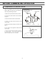
1
INSTRUCTION MANUAL
MBR-304DR
MBR-304GR
MBR-304D
MBR-304G
Blood Bank Refrigerator
MBR-304G
Note:
1. No part of this manual may be reproduced in any form without the expressed written
permission of SANYO.
2. The contents of this manual are subject to change without notice.
3. Please contact SANYO if any point in this manual is unclear or if there are any
inaccuracies.
SANYO Electric Biomedical Co., Ltd.
All rights reserved.
Printed in Japan.
CONTENTS
PRECAUTIONS FOR SAFE OPERATION
P. 2
CAUTIONS FOR USAGE
P. 6
ENVIRONMENTAL CONDITIONS
P. 7
REFRIGERATOR COMPONENTS
P. 8
INSTALLATION
P. 11
BEFORE COMMENCING OPERATION
P. 13
START-UP OF UNIT
P. 15
OPERATING INSTRUCTIONS
P. 16
ALARMS & SAFETY FUNCTIONS
P. 19
ROUTINE MAINTENANCE
P. 20
DISPOSAL OF UNIT
P. 21
TROUBLESHOOTING
P. 22
SPECIFICATIONS
P. 23
PERFORMANCE
P. 23
SAFETY CHECK SHEET
P. 24
1
PRECAUTIONS FOR SAFE OPERATION
It is imperative that the user complies with this manual as it contains
important safety advice.
Items and procedures are described so that you can use this unit correctly and safely.
If the precautions advised are followed, this will prevent possible injury to the user and
any other person.
Precautions are illustrated in the following way:
WARNING
Failure to observe WARNING signs could result in a hazard to personnel
possibly resulting in serious injury or death.
CAUTION
Failure to observe CAUTION signs could result in injury to personnel and
damage to the unit and associated property.
Symbol shows;
this symbol means caution.
this symbol means an action is prohibited.
this symbol means an instruction must be followed.
Be sure to keep this manual in a place accessible to users of this unit.
< Label on the unit >
This mark is labeled on the cover in which the electrical components of high voltage are
enclosed to prevent the electric shock.
The cover should be removed by a qualified engineer or a service personnel only.
2
PRECAUTIONS FOR SAFE OPERATION
WARNING
Do not use the unit outdoors. Current leakage or electric shock may result if the unit is exposed to
rain water.
Only qualified engineers or service personnel should install the unit.
unqualified personnel may cause electric shock or fire.
The installation by
Install the unit on a sturdy floor. If the floor is not strong enough or the installation site is not
adequate, this may result in injury from the unit falling or tipping over.
Never install the unit in a humid place or a place where it is likely to be splashed by water.
Deterioration of the insulation may result which could cause current leakage or electric shock.
Never install the unit in a flammable or volatile location. This may cause explosion or fire.
Never install the unit where acid or corrosive gases are present as current leakage or electric
shock may result due to corrosion.
Use a dedicated power source as indicated on the rating label attached to the unit. Ensure that a
suitable fuse of adequate amperage is used to allow for compressor start up.
Remove dust from the power supply plug before inserting in a power source. A dusty plug or
improper insertion may pose a hazard.
Use a power supply outlet with ground (earth) to prevent electric shock. If the power supply
outlet is not grounded, it will be necessary to install a ground by qualified engineers.
Never ground the unit through a gas pipe, water main, telephone line or lightning rod. Such
grounding may cause electric shock in the case of an incomplete circuit.
Do not insert metal objects such as a pin or a wire into any vent, gap or any outlet for inner air
circulation. This may cause electric shock or injury by accidental contact with moving parts.
Never store volatile or flammable substances in this unit. This may cause explosion or fire.
Never store corrosive substances in this unit. This may lead to damage to the inner components
or electric parts.
If this unit is to be used for storing poisons, radioactive material or other harmful products,
ensure that it is in a safe area. Failure to do so may lead to an adverse effect on the health of
personnel in the area and the local environment. In this case, a request for repair or maintenance
will necessitate a safety check sheet for maintenance personnel.
3
PRECAUTIONS FOR SAFE OPERATION
WARNING
Disconnect the power supply to the unit prior to any repair or maintenance of the unit in order to
prevent electric shock or injury.
Ensure you do not inhale or consume medication or aerosols from around the unit at the time of
maintenance. These may be harmful to your health.
Never splash water directly onto the unit as this may cause electric shock or short circuit.
Never disassemble, repair, or modify the unit yourself. Any such work carried out by an
unauthorized person may result in fire or injury due to a malfunction.
Disconnect the power supply plug before replacement of the florescent light to prevent electric
shock.
Disconnect the power supply plug if there is something wrong with the unit.
abnormal operation may cause electric shock or fire.
Continued
If the unit is to be stored unused in an unsupervised area for an extended period, ensure that
children do not have access and that doors cannot be closed completely.
The disposal of the unit should be undertaken by appropriate personnel. Remove door to
prevent accidents such as suffocation.
Prepare a safety check sheet when you request any repair or maintenance for the safety of service
personnel.
Do not pull out more than 2 drawers at the same time (MBR-304DR, MBR-304GR) when storing
or taking out of the stocked material. This may cause injury by falling or tipping of the unit if
something heavy items are stored.
CAUTION
Select a level and sturdy floor for installation. This precaution will prevent the unit from tipping.
Improper installation may result in water spillage or injury from the unit tipping over.
Never install the unit in a place where the possibility exists that an object may fall on it. There
are cooling circuits and electric components in the upper part of this unit. Current leakage or electric
shock may be caused if an object falls on it.
4
PRECAUTIONS FOR SAFE OPERATION
CAUTION
Connect the unit to a power source as indicated on the rating label attached to the unit. Use
of any other voltage or frequency other than that on the rating label may cause fire or electric shock.
Fix the shelves securely (MBR-304D, MBR-304G). Incomplete installation may cause injury or
damage.
When removing the plug from the power supply outlet, grip the power supply plug, not the cord.
Pulling the cord may result in electric shock or fire by short circuit.
Never damage or break the power supply plug or cord. Do not use the supply plug if its cord
is loose. This may cause fire or electric shock.
Do not touch any electrical parts such as the power supply plug or any switches with a wet hand.
This may cause electric shock.
Do not put a container with water or heavy articles on the unit. Injury may be caused if the
articles fall. Current leakage or electric shock may result from the introduction of spilled water into
electrical components.
Do not climb onto the unit. This may cause damage to the unit and cause it to tip over.
Hold the handle when closing the door. This will reduce the likelihood of a trapped finger.
Do not lean on the door.
This may cause injury if the unit tips over.
Never place your hand on the glass or use excessive force on the glass. Intentional force may
break the glass resulting in injury from the broken glass.
Do not touch the condenser directly when the filter is removed for cleaning.
due to hot surface.
This may cause injury
Disconnect the power supply plug before moving the unit. Take care not to damage the power
cord. A damaged cord may cause electric shock or fire.
Dispose of any water in the evaporation tray completely before moving the unit. Spilled or
splashed water may cause current leakage or electric shock.
Be careful not to tip the unit over during movement to prevent damage or injury.
Disconnect the power plug when the unit is not used for long periods.
Do not put the packing plastic bag used in the packaging within reach of children as suffocation
may result
5
CAUTIONS FOR USAGE
• If the unit is unplugged or the power to the unit is interrupted, do not restart the unit for at least 5
minutes. This protects the compressor.
• This inner cabinet is refrigerated by the forced circulation of cooled air inside the chamber. Ensure that
the intake and exhaust vents are not blocked. Adequate space should be provided between the items
inside the unit to allow air circulation.
• Never store corrosive materials such as acid or alkali where the container is not completely sealed.
This could possibly lead to corrosion of the evaporator resulting in refrigerant leakage and subsequent
loss of cooling ability.
• Once the chamber temperature has stabilized, put the items into the chamber in small batches to
minimize the temperature increase.
• In the case where condensation forms on the front of the glass due to high ambient humidity, wipe it off
with a soft and dry cloth.
• For the cleaning of the unit, use a cloth containing diluted neutral dishwashing detergent (Undiluted
detergent may break the plastic parts. For the dilution, follow the instruction enclosed with the
detergent). When a diluted neutral dishwashing detergent is used to clean the unit, wipe the unit
thoroughly with a cloth soaked in clean water. Then wipe the unit with a dry cloth to eliminate the
moisture.
• Do not clean the unit with scrubbing brushes, acid, thinner, solvents powdered soap, cleanser or hot
water. These agents can scratch the paint or cause it to peel. Plastic and rubber parts can be easily
damaged by these materials. Especially never use any volatile solvent to clean the plastic or rubber
parts.
• Fix the shelves securely (MBR-304D, MBR-304G). Place items on the shelves and leave a space
between the walls of the cabinet and the contents to allow air circulation. Do not place items on the floor
of the chamber.
• Always close the door firmly. The door check lamp is lit when the door is open. The alarm buzzer
sounds two minutes after door opening. The buzzer can be cancelled automatically when the door is
closed.
• Always open and close the door gently. Rough handling of the unit may lead to stocked items tipping
over, incomplete closing of the door, or damage to the door gasket.
• Do not put any articles on the unit. Blocking of the top will decrease the heat discharge which can
cause poor cooling and failure of the unit.
6
ENVIRONMENTAL CONDITIONS
This equipment is designed to be safe at least under the following conditions (based on the IEC 1010-1):
1. Indoor use;
2. Altitude up to 2000 m;
3. Ambient temperature 5oC to 40oC
4. Maximum relative humidity 80% for temperature up to 31oC decreasing linearly to 50% relative humidity
at 40oC;
5. Mains supply voltage fluctuations not to exceed ±10% of the nominal voltage;
6. Other supply voltage fluctuations as stated by the manufacturer.
7. Transient overvoltages according to Installation Categories (Overvoltage Categories) II; For mains
supply the minimum and normal category is II;
8. Pollution degree 2 in accordance with IEC 664.
7
REFRIGERATOR COMPONENTS
3
1
2
5
4
6
20
10
11
7
12
13
8
21
14
9
15
18
16
17
MBR-304G
8
19
REFRIGERATOR COMPONENTS
1. Door switch: To detect the door status (open/close).
2. Battery switch: ON-OFF switch for built-in battery for power failure alarm. Always turn on this
switch when the refrigerator is operated. Turn off this switch when the refrigerator is not used for long
period to protect the battery.
3. Power switch: Main switch of the unit.
4. Glow starter: For a fluorescent lamp. It is recommended to replace the glow starter at the time of
replacement of fluorescent lamp. Refer to page 21 for the replacement.
5. Control panel: Panel can be opened when upper right corner of the lower part cover is pushed.
The running status is displayed on this panel and temperature setting is accomplished through this panel.
Refer to page 10 for details.
6. Light switch:
This switch is used for turning the fluorescent lamp off and on.
7. Glass window: The window may have condensation in high humidity environment. Wipe off the
condensation with a soft dry cloth.
8. Handle: Always hold the handle when opening/closing the door.
9. Lock: Turn the key counterclockwise through 180o to securely lock the door.
10. Fluorescent lamp: 15 W lamp. Normally turn off the lamp. See page 20 for the replacement.
11. Monitor bottle for temperature sensor (2 locations): The bottles has a sensor to display the
chamber temperature. Fill the bottle with 200ml of 10% glycerol or water before commencing the
operation. Refer to page 13 for filling the monitor bottle.
12. Access port: This port allows temperature measurement cables or sensors to enter the chamber
from outside.
13. Shelf (MBR-304D, MBR-304G), Drawer (MBR-304DR, MBR-304GR): Items to be stored in the
chamber must be placed on the shelves or drawers. The maximum storage weight for each shelf or
drawer is 20 kg. Do not put stored items directly onto the interior floor of the chamber.
14. Condensation tray: The condensation on the door is accumulated in this tray. Wipe off the water
occasionally.
15. Caster: Used when moving the unit. When installing the unit the castors can be raised from the
ground by using the leveling feet.
16. Leveling foot: Adjust the height of the leveling foot to install the refrigerator in level. See page 12
for details.
17. Automatic temperature recorder: For details, see the instruction manual of the recorder enclosed
with the unit.
18. Air exhaust vent:
direct cooled air.
Do not block this vent. Care should be taken not to expose the stored items to
19. Inner door: Made of acrylic resin. For cleaning, use the diluted neutral dishwashing detergent
20. Air intake vent: Do not block this vent. If this vent is blocked, temperature regulation will become
unstable. Do not insert fingers or any substances into the vent because the circulating fan is running
inside the vent.
21. Door latch:
separately.
By turning the latch downward, the door is locked.
9
A padlock can be provided
REFRIGERATOR COMPONENTS
Control panel and keypad
7
8
9
1
2
1. Alarm buzzer stop key (BUZZER):
10
3
11
4
5
6
To silence the audible alarm, press this key.
2. Temperature display key (UPPER/LOWER): By pressing this key, the displayed temperature is
changed; upper monitor bottle temperature, lower monitor bottle temperature, and average temperature
of upper and lower monitor bottles are displayed in sequence.
3. Alarm test key (ALARM TEST): To check the operation of alarm buzzer, lamp, and remote alarm
terminal.
4. Calibration key (CAL): To calibrate the temperature. This key is used only when the temperature
calibration is necessary.
5. Digit shift key (
): Pressing this key in the CAL mode will cause the changeable digit to shift.
6. Numerical value shift key (
to change.
7. Door check lamp (DOOR):
): Pressing this key in the CAL mode will cause the numerical value
This lamp is lit when the door is ajar or open.
8. Alarm lamp (ALARM): This lamp blinks during an alarm condition (temperature alarm or power
failure alarm).
9, 10. Temperature display monitor lamp (UPPER, LOWER): Lamp 9 is lit when upper monitor bottle
temperature is displayed. Lamp 10 is lit when lower monitor bottle temperature is displayed.
Both 9 and 10 are lit when the average temperature of lower and upper monitor bottle temperature is
displayed.
11. Digital temperature indicator:
This indicator shows the current chamber temperature.
10
INSTALLATION
Installation site
To operate this unit properly and to obtain maximum performance, install the unit in a location with the
following conditions:
• A location not subjected to direct sunlight
Installation in a location subjected to direct sunlight may lead to inadequate cooling.
• A location with adequate ventilation
Leave at least 10 cm around the unit for ventilation. Poor ventilation will result in a reduction of the
refrigeration capacity.
• A location away from heat generating sources
Avoid installing the unit near heat-emitting appliances such as gas ranges or stoves. Heat can cause
inefficient refrigeration.
• A location with a sturdy and level floor
WARNING
Install the unit on a sturdy floor. If the floor is not strong enough or the installation site is not
adequate, this may result in injury from the unit falling or tipping over.
Select a level and sturdy floor for installation. This precaution will prevent the unit from tipping.
Improper installation may result in water spillage or injury from the unit tipping over.
• A location where objects will not fall on the unit
CAUTION
Never install the unit in a place where the possibility exists that an object may fall on it. There are
cooling circuits and electric components in the upper part of this unit. Current leakage or electric shock
may be caused if an object falls on it.
• A location not prone to high humidity
WARNING
Do not use the unit outdoors. Current leakage or electric shock may result if the unit is exposed to
rain water.
Never install the unit in a humid place or a place where it is likely to be splashed by water.
Deterioration of the insulation may result which could cause current leakage or electric shock.
• A location without flammable or corrosive gas
WARNING
Never install the unit in a flammable or volatile location. This may cause explosion or fire.
Never install the unit where acid or corrosive gases are present as current leakage or electric shock
may result due to corrosion.
11
INSTALLATION
Installation
1. Remove the packaging materials and tapes
Remove all transportation packaging materials and
tapes. Open the doors and ventilate the unit. If
the outside panels are dirty, clean them with a
diluted neutral dishwashing detergent. (Undiluted
detergent can damage the plastic components.
For the dilution, refer to the instruction of the
detergent.) After the cleaning with the diluted
detergent, always wipe it off with a wet cloth.
Then wipe off the panels with a dry cloth.
2. Adjust the leveling foot
Extend the leveling feet by rotating them as shown
in the figure until they make contact with the floor.
Ensure the unit is level. (Fig. 1)
Leveling foot
Fig. 1
3. Fix the unit
Two fixtures are attached to the rear of the frame.
Fix the frame to the wall by attaching a rope or
chain between the wall and the fixtures.
4. Install the filter
Install the condenser filter at the front bottom of the
cabinet. (Fig. 2)
Fig. 2
4. Ground (earth)
WARNING
Use a power supply outlet with ground (earth) to prevent electric shock. If the power supply outlet is
not grounded, it is necessary to install a ground by qualified engineers.
Never ground the unit through a gas pipe, water main, telephone line or lightning rod. Such
grounding may cause electric shock in the case of an incomplete circuit.
12
BEFORE COMMENCING OPERATION
Preparation of monitor bottle
Prior to the operation of the unit, fill the monitor
bottles (upper and lower) with 10% glycerol or
water using the following procedure:
Recorder sensor
(lower bottle of MBR-304G
and MBR-304GR)
Temp. sensor
1. Remove the top and bottom drawer (or shelf).
2. Remove the monitor bottle cover as shown in
the figure 1.
3. Take out the sensor from the monitor bottle.
4. Remove the fixing screw and take out the
monitor bottle.
5. Remove the cap by loosing it as shown in the
figure 2.
Fixing screw
6. Pour 200ml of 10% glycerol or water into the
monitor bottle.
Cover
Fig. 1
Cap
Loosen
7. Cap the monitor bottle and replace the bottle to
its original position. Then set the sensor to the
bottle and replace the cover on the bottle.
Fig. 2
13
BEFORE COMMENCING OPERATION
Remote alarm terminal
The terminal for remote alarm is installed inside the rear
cover of the unit. The alarm is outputted from this
terminal.
The contact rating is DC 30V, 2 A.
Contact output: At normal condition “Open”
At abnormal condition “Close”
Note:
The contact is “Close” because it is regarded as
abnormal when the power supply cord is disconnected
from the outlet or the power switch is turned off, or in
the event of power failure.
The remote alarm is in conjunction with the alarm
buzzer, the alarm can be silenced by pressing the alarm
buzzer stop key (BUZZER) except for in the case of
power failure
14
Terminal
START-UP OF UNIT
Follow the procedures for the initial and consequent operations of the unit.
1. Connect the power cord to the dedicated outlet with appropriate rating.
2. On start-up, the alarm buzzer sometimes operates. In this case, stop the buzzer by pressing the
buzzer stop key (BUZZER). The alarm will operate until the temperature monitor bottle sensor goes into
the range of 4oC±2oC.
3. Ensure that both monitor bottles have been filled with 10% glycerol or water as outlined on page 13.
4. The unit has been factory preset to operate at 4oC±1oC. There is no need to set the temperature.
5. It takes several hours to stabilize the chamber temperature at the set temperature. Once the unit has
stabilized, ensure the monitor bottle temperature corresponds with the set temperature.
6. Turn on the fluorescent light switch to check the light. After checking, turn off the switch if the lighting
is not necessary.
7. Once the unit operation has been thoroughly checked, begin slowly placing items into the chamber to
minimize the temperature rise.
Operation after power failure
The refrigerator resumes the operation with temperature setting of 4oC after power failure.
15
OPERATING INSTRUCTIONS
Storing of items
Do not disturb the air circulation in the chamber by the stored items. The disturbed air circulation can
cause the freezing of stored items or degrade of temperature distribution in the chamber.
Air-intake vent
Do not block the air-intake by the stored items near the air-intake vent. Take should be taken not to put
any paper or plastic chips near the vent. They may be vacuumed up and block the vent.
Air-exhaust vent
Do not block the air-exhaust by the stored item near the air-exhaust vent. The stored item may be
frozen if they put nearby the air-exhaust vent.
Load line
The stock area is limited to ensure the air flow in the chamber. The labels “load line” are attached to the
right and left side of the chamber. Always put the items within the specified area.
Note:
Do not stock any corrosive materials when the container is not sealed completely.
corrosion of inner components or evaporator.
16
Such material causes
OPERATING INSTRUCTIONS
Temperature display
The unit is set at the factory to obtain the proper temperature automatically (4oC±1oC). There is no
need to set the temperature.
Table 1.
●: Lamp ON
Temperature display
Operation
Key operated
Plug-in the power
1
supply cord and turn on
-----
the power switch.
2
3
4
5
○: Lamp OFF
Display
Display mode
Average monitor bottle
● UPPER
temperature
● LOWER
Press the temperature
UPPER
Upper monitor bottle
● UPPER
display key.
LOWER
temperature
○ LOWER
Press the temperature
UPPER
Lower monitor bottle
○ UPPER
display key.
LOWER
temperature
● LOWER
Press the temperature
UPPER
Average monitor bottle
● UPPER
display key.
LOWER
temperature
● LOWER
Average temperature
Upper temperature
Lower temperature
Average temperature
Repeat from step 2.
Note:
The displayed temperature represents the temperature sensed by a thermal sensor attached to the
monitor bottle mounted to the upper and lower portion of the chamber.
The displayed temperature may not always be at 4oC. Because the chamber probes are representative
of high and low average temperatures within the chamber.
Defrost cycles
There is no need for routine defrosting of the unit as this occurs automatically as follows:
1. Cycle defrost
To keep the chamber temperature stable, the refrigeration compressor is cycled on and off. During “off”
period any frost which has accumulated on the evaporator is melted by energizing a defrost heater. This
will not have any discernible effect on the chamber temperature.
2. Forced defrost
When the ambient humidity is high, or a large amount of damp product is being stored inside the chamber,
there is a possibility that cycle defrost may not be enough to remove all of the frost on the evaporator. In
this case, a forced defrost cycle can be initiated.
When the unit is operating under a forced defrost cycle, the current chamber temperature and “dF” is
displayed alternately on the digital temperature display.
Once the forced defrost cycle is completed, normal operation resumes.
The temperature of blood bag (400mL) in the chamber rises by approximately 1 to 2oC during the
defrosting.
17
OPERATING INSTRUCTIONS
Calibration of temperature sensor
The temperature sensors are attached to the monitor bottles. Follow the instructions below for proper
calibration of temperature sensor.
Recorder sensor
(lower bottle of MBR-304G
and MBR-304GR)
1. Remove the monitor bottle cover as shown in
Temp. sensor
the figure.
2. Remove the sensor to be calibrated from the
monitor bottle. Please note that MBR-304G and
MBR-304GR also has a sensor for the temperature
recorder in the left side of the lower monitor bottle.
3. Prepare a bottle or beaker with a solution of
crushed ice and cold water. Agitate the mixture
thoroughly.
4. Put the sensor to be calibrated in the mixture.
5. Select the temperature display by pressing
temperature display key to show the proper
temperature. While continuously agitating the ice
Cover
Fixing screw
water mixture, monitor the temperature indicated
on the display of the sensor to be calibrated.
6. Wait for the temperature on the display to stabilize. If the display is not 0oC, calibrate using the
following procedure. If the display does indicate 0oC, proceed to step 7.
6-1. Press the CAL key for approximately 5 seconds until C00 is displayed.
6-2. Enter the code of the probe to be calibrated using the numerical value shift key ( ).
Upper chamber temperature sensor code is C01.
Lower chamber temperature sensor code is C02.
6-3. Press the CAL key. (This makes temperature display 0oC)
This key operation is canceled with the buzzer if the sensor temperature deviates over +/- 1.5oC.
In this case, consult with Sanyo dealer or service personnel.
6-4. The digital display will revert back to current chamber temperature. The calibration that was
entered in the previous step should now have an effect on the temperature display.
The digital display should now show indicate 0.0±0.2oC, if not, repeat step 6.
7. Take the sensor out of the ice water solution and wipe with a soft cloth.
8. Attach the sensor back into the monitor bottle by reversing the procedure in step 1 and 2.
* For the span adjustment, contact your service personnel.
18
ALARMS & SAFETY FUNCTIONS
This unit has the alarms and safety functions shown in Table 2, and also self diagnostic functions.
Table 2
Alarms and safety functions
Alarm & Safety
High temperature
alarm
Low temperature
alarm
Protection of
excessive high
temperature
Protection of
excessive low
temperature
Situation
If the upper or lower temperature sensor
o
senses a temperature ≧ 6 C.
If the upper or lower temperature sensor
o
senses a temperature ≦ 2 C.
If the high-temperature thermostat
sensor senses a temperature
o
approximately > 10 C.
Indication
Buzzer
Alarm lamp flashes.
Intermittent tone
Remote alarm
Alarm lamp flashes.
Intermittent tone
Remote alarm
If the alarm sensor senses a
o
temperature approximately < 2 C.
-----
-----
Compressor ON.
Heater OFF.
-----
-----
Compressor ON.
Heater OFF.
Power failure alarm
When the power to the unit is
disconnected or power switch is
turned off.
Alarm lamp flashes.
Intermittent tone
Door alarm
When the door is ajar or open.
Door check lamp is lit.
Intermittent tone
with 2 minutes
delay.
When there is no key pressing in
each setting mode for 90 seconds.
If the temperature sensor of upper
monitor bottle is disconnected or
short-circuited.
If the temperature sensor of lower
monitor bottle is disconnected or
short-circuited.
Monitor bottle temperature is
displayed.
Alarm lamp flashes.
E1 and monitor bottle temp.
are displayed alternately.
Alarm lamp flashes.
E2 and monitor bottle temp.
are displayed alternately.
Alarm lamp flashes.
E3 and monitor bottle temp.
are displayed alternately.
Alarm lamp flashes.
E4 and monitor bottle temp.
are displayed alternately.
Auto-return
Thermal sensor
abnormality
If the defrost sensor is disconnected or
short-circuited.
If the over-temperature sensor is
disconnected or short-circuited.
Safety operation
-----
Remote alarm.
----Finishing of calibration
mode.
Intermittent tone
Remote alarm.
Intermittent tone
Remote alarm.
Intermittent tone
Remote alarm.
Intermittent tone
Remote alarm.
Note:
The remote alarm is silenced by pressing the buzzer stop key (BUZZER) as the remote alarm is operated
in conjunction with the buzzer, except for the power failure alarm. All alarm functions will auto-reset.
The buzzer and remote contacts will re-activate if the condition which caused the alarm is not corrected
within 30 minutes.
Alarm conditions will remain active for about 24 hours on a fully charged back-up battery in the event of a
power failure. Two days operation is required to fully charge the battery after initial start-up if the power
has been off for an extended period.
The remote alarm contacts will remain active even if the battery is discharged.
Alarm test procedure
The alarm function can be checked by the following procedure:
1. Press alarm test (ALARM/TEST) key.
2. The audible and visual alarm indicators activate along with the remote alarm. The alarm condition
remains active for 30 seconds and then terminates automatically. The audible alarm (buzzer) cannot be
silenced by pressing the buzzer stop key (BUZZER).
3. Otherwise the alarm test can be terminated manually at any time during the rest by pressing the
ALARM/TEST key again.
19
ROUTINE MAINTENANCE
WARNING
Always disconnect the power supply to the unit prior to any repair or maintenance of the unit in
order to prevent electric shock or injury.
Ensure you do not inhale or consume medication or aerosols from around the unit at the time of
maintenance. These may be harmful to your health.
Cleaning of cabinet
• Clean the unit once a month. Regular cleaning keeps the unit looking new.
• Use a dry cloth to wipe off small amounts of dirt on the outside and inside of the unit and all accessories.
If some of them are dirty, use a cloth containing diluted neutral dishwashing detergent (Undiluted
detergent may break the plastic parts. For the dilution, follow the instruction enclosed with the
detergent). When a diluted neutral dishwashing detergent is used, wipe the cabinet or accessories
thoroughly with a cloth soaked in clean water. Then wipe the cabinet or accessories unit with a dry cloth
to eliminate the moisture.
• Never pour water onto or into the unit. Doing so can damage the electrical insulation and may cause
electric shock or short circuit.
• The compressor and other mechanical part are completely sealed. This unit requires absolutely no
lubrication.
• Remove dust from the power supply plug periodically. A dusty plug or improper insertion may pose a
hazard.
Replacement of fluorescent lamp
The fluorescent lamp is placed horizontally in the upper front of the chamber. Follow the procedure
below to replace the lamp.
1. Turn off the fluorescent light switch and disconnect
the power supply plug.
2. Hold the cover of the light and pull downward with
lead wire to remove the lamp from stopper. (Fig. 1)
3. Remove the water-proof rubber on the left. (Fig.
2)
4. Remove the socket on the left. (Fig. 2)
5. Take out the fluorescent lamp gently from the
protective cover.
6. After placing a new fluorescent lamp in the
protective cover, replace the socket and then replace
the water-proof rubber.
7. Fix the light with the stoppers.
Fig. 1
Water-proof rubber
Socket
Fig. 2
20
ROUTINE MAINTENANCE
Replacement of glow starter
A glow starter is located upper right side of the cabinet..
1. Disconnect the power supply plug.
2. Remove the glow starter and replace with a new
one.
Glow starter
3. Replace the water-proof rubber.
Cleaning of condenser filter
This unit is provided with the condenser filter at the bottom of the cabinet. Clean the filter once a month
even since a clogged filter may cause shorter compressor life as well as the poor cooling.
Clean the filter by the procedure below.
1. Turn off the power switch.
2. Take out the condenser filter as shown in the
figure.
3. Wash the filter with water and dry it naturally.
4. Replace the filter.
DISPOSAL OF UNIT
WARNING
If the unit is to be stored unused in an unsupervised area for an extended period ensure that children
do not have access and doors cannot be closed completely.
The disposal of the unit should be accomplished by appropriate personnel. Always remove
doors to prevent accidents such as suffocation.
廢電池
請回收
This product has an electric battery.
Please recycle it for effective utilization of resources and protection of our environment.
Thank you for your cooperation.
Label indication is obliged to comply with Taiwanese battery regulation.
21
TROUBLESHOOTING
If the unit malfunctions, check out the following before calling for service.
If nothing operates even when switched on
• The power is failed.
• The circuit breaker is inactivated.
• The unit is not connected to the power supply.
The alarm device is activated
• The temperature in the unit does not match the set value. (On start-up)
• The door was kept opened for a long time.
• The high temperature materials (load) were put in the unit.
In these cases, the alarm is removed automatically by running the unit for several hours.
When the unit does not get cold enough
• A large amount of items or warm products was put in the unit.
• The air-exhaust vent is blocked up with containers.
• The unit is in direct sunlight.
• The door is frequently opened.
• A heat source is nearby the unit.
• The ambient temperature is too high.
• The door is not securely closed.
• The heat source is put in the unit.
• The door seal is damaged or foreign substance is inserted between door gasket.
22
SPECIFICATIONS
Name
Model
Blood Bank Refrigerator
MBR-304D
MBR-304G
MBR-304DR
External dimensions
W600 x D680 x H1835 (mm)
Internal dimensions
W520 x D490 x H1150 (mm)
Effective capacity
304 L
MBR-304GR
302 L
Exterior
Acrylic finish baked on zinc galvanized steel
Interior
Acrylic finish baked on zinc galvanized steel
Door
1 door with glass window
Insulation
Shelf
Drawer
Rigid polyurethane foamed-in place
Hard steel wire on polyethylene coating
5 pcs.
-----
-----
Stainless steel, Handle with card holder
5 pcs.
Left side, Inner diameter 30 mm
Access port
Cooling method
Forced cool air circulation
Compressor
Hermetic type, Output; 175 W
Condenser
Fin and tube type
Evaporator
Fin and tube type
Refrigerant
R-134a
Temperature controller
Electronic control system
Temperature display
Alarm
Digital display
High temperature, Low temperature, Door, Power failure, Sensor
Remote alarm contact
Allowable contact capacity: 30 VDC, 2 A
Memory back-up
Nonvolatile static memory
Fluorescent lamp
White light 15 W x 1 (Glow starter; FG-1P)
Temperature recorder
30-day type
7-day type
Accessories
30-day type
7-day type
1 set of key
Battery
6 VDC, 1100 mAh (Ni-MH)
Weight
125 kg
140 kg
Note: The contents of this manual are subject to change without notice.
PERFORMANCE
Monitor bottle temperature
+4oC±1oC
Usable ambient temp.
+5 to 35oC
Power failure alarm
duration
Power source
Rated power consumption
Noise level
24 hours (when the battery is full charged)
110V
60Hz
220W
115V
60Hz
220W
220V
50Hz
220W
220 V
60Hz
220W
230 V
50Hz
220W
240 V
50Hz
220W
41 dB [A] (background noise; 20 dB)
Maximum pressure
1275 kPa
Note :The unit with CE mark complies with EC directives 89/336/EEC, 93/68/EEC and 73/23/EEC.
23
220-240V,
50Hz
220W
CAUTION
Please fill in this form before servicing.
Hand over this form to the service engineer to keep for his and your safety.
Safety check sheet
1. Refrigerator contents :
Risk of infection:
Risk of toxicity:
Risk from radioactive sources:
□Yes
□No
□Yes
□Yes
□Yes
□No
□No
□No
(List all potentially hazardous materials that have been stored in this unit.)
Notes :
2. Contamination of the unit
Unit interior
No contamination
Decontaminated
Contaminated
Others:
□Yes
□No
□Yes
□Yes
□Yes
□No
□No
□No
3. Instructions for safe repair/maintenance of the unit
□Yes
□No
a) The unit is safe to work on
□Yes
□No
b) There is some danger (see below)
Procedure to be adhered to in order to reduce safety risk indicated in b) below.
Date :
Signature :
Address, Division :
Telephone :
Product name :
Blood Bank Refrigerator
Model :
Serial number :
MBR-
Please decontaminate the unit yourself before calling the service engineer.
24
Date of Installation :
7FB6P101379001
(9 Sept. 2004)
Recycled paper
SANYO Electric Biomedical Co., Ltd.
CEM
10-15, Hongo 3-Chome
Bunkyoku, Tokyo 113-8434 Japan
Printed in Japan