1
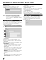
INSTRUCTION MANUAL (Supplement)
DSR-2004
Digital Video Recorder
The instruction manual has been updated with changes and additions to reflect the latest
improved product specifications.
When referring to specific parts of the instruction manual, use this supplement to identify what
changes or additions exist.
Note that the network operation software has been updated from “Sanyo DVR Utility 2004” to
“Sanyo DVR Utility 2000S”.
Table of Contents
Additions and Changes to Main Unit Operating Procedures
Setting the Summer Time
Setting the Recording Time
Marking and Copying Live Videos
Marking and Copying Playback Videos
Configuring Alarm Notification E-mail
P1
P1
P2
P2
P4
(P9)
(P13, 14, 28)
(P21)
(P22)
(P36)
Additions and Changes to Network Operations
Connecting to the DVR through the Network
Connecting to a Different Site
Backing Up Recorded Videos
Selecting the Display Language
Editing Site Information
P5
P5
P5
P5
P6
(P41)
(P41)
(P49)
(P50)
(P51)
New Feature for Network Operations (Remote Setup)
How to Use Remote Setup
Live Settings
Record Settings
System Settings
Description
PTZ Control Settings
Network Settings
Send E-Mail Settings
Storage Settings
Note:
P7
P8
P9
P11
P12
P12
P12
P13
P13
(P25)
(P27)
(P29)
(P11)
(P33)
(P36)
(P37)
Parenthesized numbers indicate the corresponding pages in the instruction manual.
Additions and Changes to Main Unit
Operating Procedures
Setting the Summer Time
• OTHER
If your summer time region is neither USA nor EU, you
have to set the beginning (BEGIN) and end (END) of
the summer time period:
(P9)
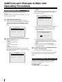
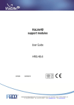
The procedure for setting the summer time has been
changed.
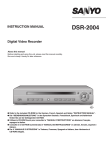
To set the summer time, display the CLOCK SET screen and
then follow the steps below:
CLOCK SET
D.S.T./SUMMER TIME
BEGIN
END
1
Display the CLOCK SET screen.
As instructed in the instruction manual, access the
menu screen and choose [SYSTEM] → [CLOCK SET].
When the CLOCK SET screen appears, the cursor is
automatically placed in the [D.S.T./SUMMER TIME]
field.
2008/02/29
OTHER
MAR 1ST MON 00H
SEP 1ST MON 00H
10:20:34
1 Use the down control button (|) to choose [BEGIN]
CLOCK SET
D.S.T./SUMMER TIME
2008/02/29
and then press the ENTER button to access the
screen where you can set the beginning of the
summer time period.
OFF
10:20:30
D.S.T./SUMMER TIME BEGIN
MAR
2
Select the summer time region using the right and
left control buttons (}~).
• OFF
Turns off the summer time.
• U.S.A
Applies USA summer time.
• EU
Applies EU summer time.
Select the GMT AREA using the down control button
(|), and set the time difference using the right and left
control buttons (}~).
CLOCK SET
D.S.T./SUMMER TIME
GMT AREA
2008/02/29
EU
+00:00
1ST
MON
0 0 H
2 Use the right and left control buttons (}~) to
choose the appropriate item and then use the up
and down control buttons ({|) to select the desired
setting.
When you are done, press the ENTER button.
3 Repeat the same steps to set the end (END) of the
summer time period.
3
Place the cursor in the [D.S.T./SUMMER TIME] field,
and press the ENTER button.
The cursor moves to the date and time field.
The subsequent steps are unchanged. Set the current date
and time following the instructions given in the instruction
manual.
10:20:34
Setting the Recording Time (P13, 14, 28)
The upper limits for BY MOTION and BY EXT. SENSOR
recording times (POST EVENT RECORD) have been
extended to 15 minutes.
Available ranges:
2 - 30 SECONDS, 1 - 5, 10, 15 MINUTES
1
Additions and Changes to Main Unit Operating Procedures
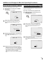
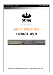
Marking and Copying Live Videos (P21)
You can mark and immediately copy a live video.
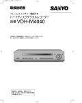
1
While monitoring a live video, press the MARK/
COPY button.
The BOOKMARK screen appears.
2%
2008/02/29 17:25:37
Marking and Copying Playback Videos
(P22)
You can mark and immediately copy a playback video in the
same way as a live video.
● To copy a still image from a playback video:
1
While playing back a recorded video, press the
MARK/COPY button
The BOOKMARK screen appears.
2008/02/29 17:25:37
BOOKMARK
NO
YES
CH1
C
BOOKMARK
2
Choose "YES" and press the ENTER button.
The current frame of the video is marked as a still
image, and the BACKUP USB DEVICE screen
appears.
2%
2008/02/29 17:25:37
STILL
VIDEO
h
CH1
2
Choose "STILL" and press the ENTER button.
The current frame of the video is marked as a still
image, and the BACKUP USB DEVICE screen
appears.
2008/02/29 17:25:37
BACKUP USB DEVICE
CD-RW
USB STICK
CH1
C
BACKUP USB DEVICE
3
Select the destination and press the ENTER button.
A confirmation screen appears.
Choose "YES" and press the ENTER button to copy the
image.
2%
2008/02/29 17:25:37
CD-RW
USB STICK
h
CH1
3
Select the destination and press the ENTER button.
A confirmation screen appears.
Choose "YES" and press the ENTER button to copy the
image.
2008/02/29 17:25:37
SAVE ?
YES
NO
CH1
C
SAVE ?
Memo: Whenever you mark a live video by pressing the
MARK/COPY button, the current frame of the video is
saved so that you can later search for and play back
the marked video through the search (BOOKMARK)
menu regardless of whether you copy it (by choosing
"YES") or just mark it (by choosing "NO").
This is also true when you have marked a playback
video.
YES
NO
CH1
h
2
Additions and Changes to Main Unit Operating Procedures
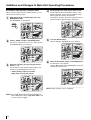
● To copy a video clip from a playback video:
When you copy a video clip from a playback video, you can
select which channel(s) to copy.
1
4
While playing back a recorded video, press the
MARK/COPY button
The BOOKMARK screen appears.
Set the length of the video clip you want to save.
Use the right and left control buttons (}~) to move
between the digits, and use the up and down control
buttons ({|) to select the desired value.
The length of the video clip can be specified in units of
minutes and the maximum length is 30 minutes.
2008/02/29 17:25:37
2008/02/29 17:25:37
CH1
CH1
CH2
CH2
DURATION & CH
BOOKMARK
STILL
0 3 MIN
VIDEO
CH3
CH3
2
CH4
CH4
h
h
Choose "VIDEO" and press the ENTER button.
The video is marked as the source of a video clip, and
the DURATION&CH screen appears.
5
Press the ENTER button.
Then the BACKUP USB DEVICE screen appears.
2008/02/29 17:25:37
2008/02/29 17:25:37
CH1
CH1
CH2
BACKUP USB DEVICE
CH2
CD-RW
USB STICK
DURATION & CH
0 0 MIN
CH3
CH3
3
CH4
h
Select the channel(s) to copy using the channel
buttons (1 - 4).
The text color of each channel number toggles each
time the corresponding button is pressed:
• Yellow (default): Copies the channel.
• White: Does not copy the channel.
2008/02/29 17:25:37
6
CH4
h
Select the destination and press the ENTER button.
A confirmation screen appears.
Choose "YES" and press the ENTER button to copy the
specified channels in order.
2008/02/29 17:25:37
CH1
CH2
SAVE ?
YES
CH1
CH3
DURATION & CH
0 0 MIN
Memo: Empty channels, if any, are skipped.
CH3
CH4
h
Memo: For a single channel video, the channel number is
always displayed in yellow ("copy the channel") and
its color cannot be toggled.
3
NO
CH2
CH4
h
Additions and Changes to Main Unit Operating Procedures
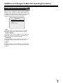
Configuring Alarm Notification E-mail
(P36)
Options have been added to the alarm notification (EVENT
ALARM) settings available through the SEND E-MAIL screen.
In addition to the OFF/ON setting, which was the only option
in the previous release, you can now narrow down the
sending conditions based on alarm event types.
SEND E-MAIL
IP NOTIFICATION
EVENT ALARM
MAIL ADDRESS
MAIL SERVER NAME
ID
PASSWORD
RETURN MAIL ADDRESS
OFF
OFF
• OFF
Selecting this option prevents the DVR from sending any
notification e-mail when an alarm event has occurred.
• BY EXT. SENSOR
Selecting this option causes the DVR to send a notification
e-mail when a sensor or similar device connected to the
DVR’s external sensor terminal is activated.
• BY MOTION
Selecting this option causes the DVR to send a notification
e-mail when its built-in motion sensor has detected
movement.
• ALL
Selecting this option causes the DVR to send a notification
e-mail when an external sensor or its built-in motion sensor is
activated.
4
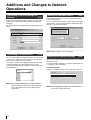
Additions and Changes to Network
Operations
Connecting to the DVR through the
Network
(P41)
Connecting to the DVR through the network for the first time
requires you to fill in the [Site Name] field of the [Connect]
dialog box.
You cannot connect to the DVR when the [Site Name] field is
blank.
Backing Up Recorded Videos
(P49)
The [AVI Backup] dialog box is now complete with channel
selector check boxes.
You can specify which channel(s) to back up by selecting the
channel boxes. Your specified channels will be backed up in
the order of the channel numbers.
Memo: Empty channels, if any, are skipped.
Connecting to a Different Site
(P41)
You can view the DVR connection information by opening the
[---Select Site---] pull down menu at the top of the operation
panel, which contains a list of site names.
To connect to another site, highlight and click the site name
from the pull down menu. This disconnects the current
connection and automatically establishes a new connection to
the specified site.
DVR1
Memo: The connection information you register with the
[Connect] dialog box when connecting to the DVR
can be changed later by choosing [Site] from the
setup menu.
5
Selecting the Display Language
(P50)
Now you can select the display language used on the network
operation screens.
To select the display language, use [General] (Miscellaneous
- Language) on the setup menu.
Available languages:
English, Thai, Italian, German, French, Spanish, Japanese
Memo: After changing the settings, restart this software to
put the new settings into effect.
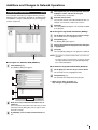
Additions and Changes to Network Operations
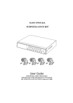
Editing Site Information
(P51)
The connection information you register with the [Connect]
dialog box when connecting to the DVR can be updated later
with additions, changes, and/or deletions by choosing [Site]
from the setup menu.
A B
C
4
On the [Channels] list, click your desired channel to
highlight it in blue, and then click it again.
The field becomes an input box.
5
Enter the channel name.
Your entered channel name will be displayed when, for
example, you monitor the video from a camera.
6
Click [OK].
Close the [Addition] dialog box. The new DVR is added
to the [Site] list.
■ To change the registered information (Modify):
D
■ To register an additional DVR (Addition):
1
Click [Addition] (A).
The [Addition] dialog box appears.
2
1
On the [Site] list, click the site you want to change.
The selected site row is highlighted in blue.
2
Click [Modify] (B).
The [Modify] dialog box appears.
3
Change the information displayed on the dialog box
as appropriate.
4
Click [OK].
Close the [Modify] dialog box. The [Site] list is updated.
Memo: You cannot set channel names when you connect to
the DVR.
To set the name of each channel, you have to change
the registered information using the [Modify] dialog
box, as described above.
■ To delete the registered information (Remove):
1
On the [Site] list, click the site you want to delete.
The selected site row is highlighted in blue.
2
Click [Remove] (C).
The selected site is deleted from the [Site] list.
☞ When you are done, click [OK] (D).
3
Your changes are applied and saved.
4
5
6
2
Enter necessary connection information such as
addresses.
You can enter the information in the same way as when
using the [Connect] dialog box (refer to page 41 of the
instruction manual).
3
In [CH Mode], set the number of DVR channels to
"4".
6
New Feature for Network Operations
(Remote Setup)
Now you can use the new network feature called Remote Setup.
With Remote Setup, you can connect your personal computer to the DVR over the network and remotely set up the DVR through
settings menus.
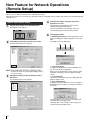
How to Use Remote Setup
1
2
Configure the settings using the menu items
displayed on screen.
These settings are basically the same as those
available through DVR-side menus.
For more information on the settings, refer to the
corresponding pages of the instruction manual.
5
Click [Apply] or [OK].
A "Remote-Setup Success" message appears on the
[Success] dialog box, and the settings are sent to the
DVR.
Click [OK] to close the dialog box.
Click the menu button on the operation panel.
The [Setup] screen appears.
Click [DVR] at the lower left corner of the screen.
The [Remote Setup] screen appears.
Memo: Some DVR models provide no support for Remote
Setup. If this is the case, pressing the [DVR] results in
an error message.
3
4
Highlight and click your desired settings menu on
the tree list.
Your specified menu screen appears.
2
3
1
1 If you click [Apply]:
The [Remote Setup] screen remains displayed after
you close the [Success] dialog box.
When you have finished all necessary Remote Setup
operations, click [OK] to close the [Remote Setup]
screen.
2 If you click [OK]:
This action closes both the [Success] dialog box and
[Remote Setup] screen.
3 If you click [Cancel]:
A dialog box that asks whether to save the settings is
displayed if there have been any settings changed on
the screen.
Choosing "No" cancels changes to the settings and
closes the [Remote Setup] screen.
Choosing "Yes" saves changes to the settings and
closes the [Remote Setup] screen.
7
New Feature for Network Operations (Remote Setup)
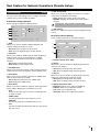
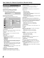
Live Settings
(P25)
You can use the LIVE settings menu to configure live mode
settings such as how to monitor live videos.
● Common settings (General)
6 VGA Screen Mode
Allows you to set how to display the software on a monitor
connected to the VGA port of the DVR.
• FULL: Displays the software in full screen mode.
• NORMAL: Displays the software with certain margins
around it.
These settings are applied to all the channels.
1
3
5
6
2
4
7
1 OSD
Allows you to choose whether to display date/time and
channel number information on screen.
• ON: Displays the images from this channel.
• OFF: Does not display images from this channel.
2 Sequence
Allows you to enable or disable Camera Switch (Sequence)
mode, in which a single screen displays the available
channels one after another in the order of the channel
numbers.
• ON: Enables Camera Switch mode.
• OFF: Disables Camera Switch mode.
Changing this setting forcibly restarts the DVR.
7 OSD Contrast
Allows you to adjust the contrast of the text displayed on the
screen.
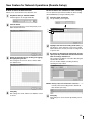
● Channel-specific Settings
These settings are specific to a particular channel.
1
2
3
4
1 Channel selector (CH1 - CH4)
2 Display
Allows you to specify the interval (1 - 60 seconds) at which to
switch from one camera to another in Camera Switch mode.
Allows you to choose whether to display images from this
channel on the monitor.
• ON: Displays the images from this channel.
• OFF: Does not display images from this channel.
4 Event Beep
3 Seq List:
Allows you to choose whether to generate an audible alarm
when an alarm event has occurred.
• ON: Enables the generation of an audible alarm.
• OFF: Disables the audible alarm.
Allows you to choose whether to display images from this
channel in Camera Switch (Sequence) mode.
• ON: Displays the images from this channel.
• OFF: Does not display images from this channel.
5 Error Alarm
4 Display adjustment sliders
3 Seq-Dwell Time
Allows you to choose whether to output an alarm signal when
the live video is disrupted or a hard disk error occurs.
• OFF:
Even if the live video is lost or if there is a hard disk error
no alarm is output.
• VIDEO LOSS:
An alarm is output when a live video loss occurs.
• HDD FAIL:
An alarm is output when a hard disk error occurs.
• ALL:
An alarm is output when both a live video loss and a hard
disk error occur.
•
•
•
•
Brightness: Allows you to adjust the brightness.
Contrast: Allows you to adjust the contrast.
Hue: Allows you to adjust the hue.
Saturation: Allows you to adjust the saturation.
8
New Feature for Network Operations (Remote Setup)
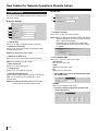
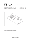
Record Settings
(P27)
You can use the RECORD settings menu to configure
recording conditions.
● Resolution (common to all channels)
Allows you to set the recorded video resolution.
This setting is applied to all the channels.
● Channel-specific Settings
These settings are specific to a particular channel.
6 Motion Sensitivity
Allows you to set the motion sensor sensitivity (1 - 9).
The smaller the setting, the higher the sensitivity.
7 Sensor Type
Allows you to set the signal polarity of alarm input from an
external sensor.
• ----- :
Ignores alarm input.
• N/O (Normally Open):
Choose this option if the signal line is normally open and
gets closed when an alarm occurs.
• N/C (Normally Closed):
Choose this option if the signal line is normally closed and
gets opened when an alarm occurs.
8 Pre Record
1
2
4
6
8
F
G
H
I
3
5
7
9
Allows you to configure the pre-event recording feature.
When enabled, this feature always maintains the most recent
five frames while overwriting the previously saved frames; this
means that you can record the immediately preceding five
frames when an alarm event occurs.
• ON: Enables the pre-event recording feature.
• OFF: Disables the pre-event recording feature.
9 Alarm Duration
Allows you to set the duration of alarm signal output (1 - 60
SECONDS).
F Alarm
1 Channel selector (CH1 - CH4)
Allows you to set the frame rate at which to record the video
(NTSC: OFF/1 - 30f/s, PAL: OFF/1 - 25f/s).
Allows you to choose whether to output an alarm signal in
response to an alarm event.
• ON: Enables the output of an alarm signal.
• OFF: Disables the output of an alarm signal.
3 Quality
G Audio
Allows you to choose one of three quality levels: BASIC,
NORMAL, and FINE.
Allows you to enable or disable audio recording.
• ON: Records video with audio.
• OFF: Disables audio recording.
2 Frame Rate
4 Recording
Allows you to set the recording mode.
• DISABLE: Disables recording.
• CONTINUOUS: Continuously records the video as long as
the DVR is on.
• BY MOTION:
Selecting this option causes the DVR to record the video
when its built-in motion sensor has detected a motion.
• BY EXT. SENSOR:
Selecting this option causes the DVR to record the video
when a sensor or similar device connected to the DVR’s
external sensor terminal is activated.
• BY SCHEDULE:
Selecting this option causes the DVR to record the video
during the scheduled time window.
5 Timer set
Set the operational schedule for timer recording (BY
SCHEDULE) using the [Schedule] screen. (For more
information on how to define the schedule, see Page 10.)
9
H Post Event Record
Allows you to set the post-event recording time (2 - 30
SECONDS, 1 - 5, 10, 15 MINUTES).
I Motion Zone
Allows you to set the motion sensor detection zone.
The "PARTIAL ZONE" option requires you to define the
detection zone. (For more information on how to define the
detection zone, see Page 10.)
• FULL ZONE: Detects a motion throughout the entire
screen.
• PARTIAL ZONE: Detects a motion within a user-defined
zone (area) only.
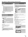
New Feature for Network Operations (Remote Setup)
● How to define the detection zone
● How to define the schedule for timer recording
Allows you to set the motion sensor detection zone.
You can define the operational schedule for timer recording
(BY SCHEDULE) by using the following steps:
1
Set [Motion Zone] to "PARTIAL ZONE".
A button appears on the right-hand side.
2
Click the button.
You are presented with a screen that prompts you to
define the detection zone.
1
Click the [Timer set] button.
The [Schedule] screen appears.
1
2
3
2
Highlight and click the recording mode button (1).
The field (2) at the upper left corner of the schedule
table indicates the currently selected recording mode in
a specific color.
3
By clicking (or dragging) the appropriate grid cells,
specify the days of the week and the time windows
when recordings should occur.
This configures the DVR to record the video during the
specified time windows.
You can combine multiple recording modes by
repeating the steps above.
Define the detection zone by clicking (or dragging)
the appropriate grid cells.
This configures the sensor to detect a motion within
your defined zone.
Memo: Clicking a day of the week button causes the
currently selected recording mode to default to all
time windows (24 hours).
4
Click [OK].
New settings are saved, and the zone definition screen
is closed.
4
Click [OK].
New settings are saved, and the [Schedule] screen is
closed.
10
New Feature for Network Operations (Remote Setup)
System Settings
You can use the SYSTEM settings menu to configure system
and clock settings.
● System Settings
1
2
3
4
5
6
1 DVR ID (P29)
Allows you to define an identifier unique to the DVR.
2 Admin Password (P30)
● Clock Set
1
2
1 Set Date & Time (P8)
Allows you to set the current date and time.
Memo: When you change the date/time settings and click the
[Apply] or [OK] button on screen, you are presented
with a confirmation dialog box.
Responding [Yes] to the dialog message forcibly
restarts the DVR so that the new date/time settings
are applied.
Allows you to set the password for configuring the DVR
through settings menus.
Memo: The default password is "1111".
3 Network Password (P31)
Allows you to set the password for network operations.
Memo: The default password is "1111".
4 Date Format (P8)
Allows you to set the date format.
5 Language (P9)
Allows you to set the display language.
6 Remote Controller ID (P32)
When using the supplied remote controller to operate the
DVR, you can set the remote controller ID (1 - 9) for
authentication.
Memo: Accepting the default (0) allows you to use the
remote controller without ID authentication.
2 D.S.T./SUMMER TIME
Allows you to select the summer time region.
• OFF (default):
Turns off the summer time.
• U.S.A:
Applies the USA summer time.
• EU:
Applies the EU summer time.
☞ Select [GMT Area] and set the time difference from
the standard time.
• OTHERS:
Applies a non-USA/EU summer time.
☞ You have to define the beginning and end of the
summer time period.
11
New Feature for Network Operations (Remote Setup)
Description
(P29)
This is a submenu under the SYSTEM settings menu.
You can use this menu to check the DVR’s version and other
information.
Network Settings
(P33)
You can use this menu to configure the DVR’s network
information.
Changing the settings on this menu forcibly restarts the
DVR.
● Network Settings
1
2
3
4
•
•
•
•
Version: Indicates the version of the firmware.
Capacity: Indicates the capacity of the hard disk.
IP Address
MAC Address
1 Port
PTZ Control Settings
(P11)
This is a submenu under the SYSTEM settings menu.
When remotely controlling a PTZ camera connected to the
RS422/485 terminal, you can use this menu to configure the
communication settings.
1
When multiple DVRs are connected to the network, you have
to configure the port number specific to each DVR.
2 Client Access
When you use network operations, make sure that this check
box is selected.
3 Band Width Saving
Select this check box when you want to save the network
bandwidth.
4 Address settings
2
3
4
1 Data Speed
Select the appropriate network type from the [Network Type]
drop-down list, and enter the necessary information, which
differs depending on your selected network type:
• If you select "LAN":
The fields require manual entries:
You have to enter the IP address, gateway, subnet mask,
and DNS server address.
• If you select "DHCP":
The fields do not require manual entries:
You do not have to enter anything.
Allows you to set the communication rate.
This setting is applied to all the channels.
2 Channel selector (CH1 - CH4)
3 Protocol
Allows you to specify which protocol to use in the specified
channel.
When multiple cameras are connected, use the same
protocol for all the cameras.
• If you select "ADSL":
Enter your login ID and password.
4 Address
Allows you to set the camera ID (0 - 63).
12
New Feature for Network Operations (Remote Setup)
● DDNS Settings
3 Mail Address
If you intend to use Sanyo’s DDNS services, choose
"SANYO" and enter your registered domain name.
Enter the recipient’s e-mail address.
4 Mail server settings
Enter the server name of your SMTP server as well as the ID
and password required to log into the SMTP server.
5 Return Mail-Address
Enter the return e-mail address.
When a notification e-mail cannot reach the specified
recipient e-mail address, then the mail is sent to this address.
Memo: • For information on how to register your domain
name, refer to the instruction manual (P35).
• If you want to use third-party DDNS services,
consult your dealer or a "Repair Service Center" in
your local area.
Send E-Mail Settings
(P36)
This is a submenu under the NETWORK settings menu.
You can use this menu to configure the DVR to automatically
send a notification e-mail to your specified address in
response to an alarm event.
Changing the settings on this menu forcibly restarts the
DVR.
1
2
3
4
5
1 IP Notification
Selecting this check box configures the DVR to send a
notification e-mail when the DVR’s IP address is changed.
2 Event Alarm
Allows you to configure the DVR to send a notification e-mail
when a specific type of event occurs:
• OFF (default)
Selecting this option prevents the DVR from sending any
notification e-mail when an alarm event has occurred.
• By Ext. Sensor
Selecting this option causes the DVR to send a notification
e-mail when a sensor or similar device connected to the
DVR’s external sensor terminal is activated.
• By Motion
Selecting this option causes the DVR to send a notification
e-mail when its built-in motion sensor has detected
movement.
• All
Selecting this option causes the DVR to send a notification
e-mail when an external sensor or its built-in motion
sensor is activated.
13
Storage Settings
(P37)
This menu provides an option to overwrite the hard disk.
If the hard disk becomes full and you want to continue
recording in overwrite mode, then select the check box
provided on this menu.
SANYO Electric Co., Ltd.
1AC6P1P3341-L8HBN/WA (0408KP)