1
'-
-.'<C-.W.W-
-- --.
...
.-
--.
uni.den@
I
.1\
L
~- --
~
~~-
.--.-
DESCRIPTION
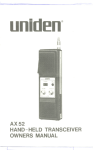
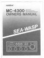
Your MC4300 represents the most advanced Mobile Station type radio ever designed
for use in the Inshore Boating Radio Communications Service, combined with unique
features for use on a boat. It will operate on any of the 10 frequencies designated as
citizens band channels by the Department of Communication. Your Model MC4300
features a frequency synthesizing circuit with PHASE LOCK LOOP techniques to
assure ultraprecise frequency control. This radio has been Type Accepted approved
by the D.O.C.
WARNING
The Inshore Boating Radio Communications Service is under the jurisdiction of the
Department of Communication
(D.O.C.). Any adjustments or alterations which
would alter the performance of the transceiver's original D.O.C. Type Approval or
which would change the frequency determining method are strictly prohibited.
Replacement or substitution
of Crystal, Transistors, IC, Regulator Diodes or any
other part of a unique nature, with parts other than those recommended by us, may
cause violation of the technical regulations of the D.O.C. Rules.
INSTAllATION
CAUTION: The
UNIDEN
ground battery system.
MC4300 will operate only with nominal
12 volt negative
It is important to carefully determine the most suitable location for your UN IDEN
MC4300 on your vessel. Electrical, mechanical, and environmental considerations
must all be taken into account. You must select the optimum relationship among
these considerations.
Some of the more important
your UNIDEN MC4300 are:
external factors to consider in selecting the location of
1. Select a location that is free from spray and splash.
2. Keep the battery leads as short as possible. Connection directly to the battery is
most desirable. If direct connection cannot be made with the supplied power lead,
any extension should be made with #14 AWG wire. Long extensions should use
larger wire.
3. Keep the antenna lead as short as possible. Long antenna le~ds can cause substantialloss of performance for both receiving and transmitting.
4. Locate your antenna as high as possible and clear from metal objects. The reliable
range of coverage is a direct function of antenna height.
-1i
--
1,-
.-=--- .._n.-
- ..-..-----
- --_. -_'_n
__n_-
r
5. Select a location that does not allow the radio to be subjected to direct sunlight
(including that coming through windows).
6. Select a location well away from the ship's compass. Auxiliary speakers also
should be located away from the compass.
ANTENNA
Since the maximum allowable power output of the transmitter is limited by the
D.O.C., the antenna is a very important factor affecting transmission distance. It is
for this reason that we strongly recommend that you install only a quality antenna in
your new citizens band system.
Only a properly matched antenna system will allow maximum power transfer from
the 50-ohm transmission line to the radiating element. Your Santronic dealer is
qualified to assist you in the selection of the proper antenna to meet your application requirements.
NOTE: A non shunt-fed antenna must be used for good weather channel reception.
The general rules for antennas are: The more gain the greater the range and the
higher above the water line the greater the range. Antennas should be located so as
not to be in proximity to metal objects. Antenna should not have excessively long
coaxial feed cables.
CONNECTING THE POWER CORDS
After you have carefully considered the various factors affecting your choice of
location, position the radio (with the bracket, microphone, power plug, antenna
plug, and any auxiliary plugs installed) into the selected location to assure there is no
interference with surrounding items. Mark the location of the mounting bracket.
Remove the bracket from the radio and use it as a template to mark the holes to be
drilled for the mounting hardware. Drill the holes and mount the bracket with
hardware compatible with the material of the mounting surface. Install the power
cable (red is +, black is -), antenna and all other auxiliary cables and accessories.
Install the radio into the mounting bracket and connect all cables and accessories to
the appropriate jacks and connectors.
OPERATING
PROCEDURE TO RECEIVE
1. Be sure that the power source, antenna and microphone are connected to the
proper connectors before going to the next steps.
i
. .i
I
I
2. Turn the unit ON by rotating the Volume Control clockwise.
3. Set the Channel Selector Switch to the desired channel.
4. Set the Volume Control to a comfortable listening level.
5.
Listen
to the
background
noise
from
the
speaker.
Turn
the
Squelch
Control
slowly clockwise until the noise JUST disappears (no signal should be present).
Leave the control at this setting. The SOU ELCH is now properly adjusted. The
receiver will remain quiet until a signal is actually received. Do not advance the
control too far, or some of the weaker signals will not be heard.
-2-
-1
.-- --"----
r
f
--~~~-
--
--.."--'
.. ---- ~- -- --=- -.-
r
I
6. To receive a weather information broadcasting, set CB WX Switch to WX position.
Then, select either WX1(156.8 MHz), WX2(156.375 MHz) by setting the switch
located next to it to a desired position.
OPERATING
PROCEDURE TO TRANSMIT
CAUTION
The transmitter Voltage Standing Wave Ratio (V.S.W.R.) measurement must
be performed prior to the use of the transmitter. A V.S.W.A. ratio in excess
of 2: 1 may damage the transmitter.
1. Be sure the operator has read and understands D.G.C. Rules and Regulations prior
to operating the transmitter.
2. Select the desired channel.
3. If the channel is clear, depress the push-to-talk switch on the microphone and
speak in a normal voice.
OPERATOR TROUBLESHOOTING
Should the unit malfunction or not perform properly, the operator should perform
the procedures indicated below:
1. If the transceiver is completely inoperative.
* Check the power cord and fuse.
2. If trouble is experienced with receiving.
* Check ON/OFF VOLUME CONTROL setting.
* Besure SQUELCH is adjusted properly. Isthe radio over-squelched?
* Check to see that the radio is switched to an operational mpde.
3. If trouble is experienced with transmitting.
* Check to see that the transmission line (coaxialcable) is securely connected to
the ANTENNA CONNECTOR.
* Be sure that the antenna is fully extended for proper operation.
* Be sure that all transmission line (coaxial cable) connections are secure and free
of corrosion.
. I
-3-
=c
--".--
'on'.."-"
on.-'
'
'
""-' -. --"---'
r
f
~
;;
, .~,"~
SPECI FICA TIONS
GENERAL
RECEIVER
Channels
RADIOTELEPHONY: 10
WX
:2
Frequency
RADIOTELEPHONY: 27.680 - 27.980
WX
: CH 16 156.8MHz
CH 67 156.375MHz
Microphone
: 500 ohm, Dynamic
Type
: 3 inches, 16 ohms
Speaker
Size
: 160(W) x 55(H) x
217(0) mm
: 1.2 Kgs
Weight
Accessories
: DC Power Cable with
Built-in Fuse Microphone, Microphone
Hanger
Maximum Sensitivity
Threshold Squelch
Sensitivity:
Tight Squelch Sensitivity:
Adjacent Channel Selectivity
at :t1OkHz (1 Signal)
Image Rejection Ratio
a. -910kHz
b. -21.39MHz
Audio Output Power
a. Maximum
b. 10% THD
S-Meter Sensitivity at "S-9"
TRANSMITTER
Frequency Tolerance
25°C 13.8V
R F Power Output
: :to.0005
:4W
: 0.5p.V
1.0 p.V
1000 p.V
: 70 dB
: 70dB
: 70dB
:5W
:4W
: 100p.V
RECEIVER (WX)
Sensitivity for 12 dB SINAD : 0.5 p.V
SIN at 1 mV Input
: 60 dB
Audio Output Power
a. Maximum
:5W
b. 10% THD
:4W
%
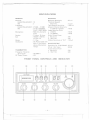
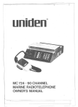
FRONT PANEL CONTROLS AND IND1CATOR
(J)
@
CD
[t:::::
~
~
@
(jJ)
@
@
@
.
e e'e
wx
wx 2IOFF
OFF
@
CID
CID
11
@
. i\
-4-
---r
--
---
r
~
r
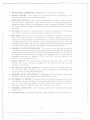
1. MICROPHONE CONNECTOR: Receptacle for microphone connection.
2. ON/OFF-VOLUME: Turn power on to radio and allows adjustment
desired listening level with clockwise rotation.
to the
3. SQUELCH/PA SWITCH: Used to quiet background noise when no signal is being
received. Proper adjustment is such that the control is advanced only siightly
beyond the point where the background noise is marginally quieted. To make
PA (Public Address), rotate the switch fully counter clockwise then, PA function
is available.
4. R F GAIN: This control is used primarily to optimize reception in strong signal
areas. Gain is reduced by counter clockwise rotation of the control.
5. MIC GAIN: The control is used to adjust as required, microphone input sensitivity for optimum amount of modulation in transmit. Uniden marine transceivers have been designed to permit the user to attain levels of modulation up
to 100% depending on the setting of the microphone gain control, using the
microphone provided with the unit. Uniden's automatic compression and peak
limiting circuits assure maximum modulation with minimum distortion.
6. CHANNEL SELECTION CONTROL: This control selects the desired channel
for transmission and reception. All channels except channel 88, may be used for
communications between stations. Channel 88 has been reserved by the D.O.C.
for emergency communications involving the immediate safety of individuals or
immediate protection of property. This is as D.O.C. rule and applies to all
operators of citizens band radios.
.
7. CB/WX SWITCH: This switch selects different operating modes. In the CB
position, WX receive function is disabled. At the WX position, CB and AN L
Functions are disabled.
8. WX1-WX2/ANL-ON OFF SWITCH: In the WX position of CB/WX SWITCH,
you can select WXl or WX2 by this switch. And when it is in CB Mode, this
switch operates as ANL ON/OFF Switch.
9. CHANNEL 88 ON OFF SWITCH: In CB Mode this switch selects channel 88,
Channel Indication will disappear and CH 88 LED will be on.
10. RF POWER/ 's" METER: This meter shows the Radio Frequency power when
transmitting and the strength of the incoming signal when receiving. A change of
one "S" unit indicates a change of 6 dB in signal level. The metering circuit is
calibrated so that for 100 microvolts, the "S" meter will read S-9.
11. CHANNEL INDICATOR:
number in use.
Light Emitting Diode (LED) indicates the channel
12. TX INDICATOR: Light Emitting Diode (LED) indicates red while transmitting.
-5-
======r::
}
...-..-..-......-------.
---
r
f
~
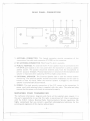
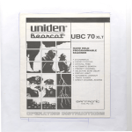
REAR PANEL CONNECTORS
CD
@
CID
@)
CID
(f)
(f)
TAIWAN
0
1. ANTENNA CONNECTOR: This female connector permits connection
transmission line cable male connector (PL-259) to the transceiver.
of the
2. WX ANTENNA CONNECTOR: RCA Type Pin Jack is available.
3. PUBLIC ADDRESS: An external 8 ohm 4-watt speaker must be connected to the
PA SPK R jack located on the rear panel when the transceiver is used as a public
address system. The speaker should be directed away from the microphone to
prevent acoustic feedback. Physical separation or isolation of the microphone and
speaker is important when operating the PA at hight output levels.
4. EXTERNAL SPEAKER: The External Speaker Jack is used for remote receive:monitoring. The external speaker should have 8-ohm impedance and be rated to
handle at least 4.0 watts. When the external speaker is plugged in, the internal
speaker is automatically disconnected.
I
I
I
I
I
.
.1
I .
5. POWER: This jack permits connection of the D.C. power to the transceiver. A
power cord with polarized plug is supplied with the radio. The polarized plug
ensures that the power will always be connected properly.
SERVICING
YOUR TRANSCEIVER
The technical information, diagrams and charts will be supplied upon request. It is
the user's responsibility to see that this radio is operating at all times in accordance
with the D.G.C. Inshore Boating Radio Communications Service regulations. We
highly recommend that you consult a qualified radiotelephone technician for the
servicing and alignment of this marine radio product.
-6-.
~--,.,--
'--'h'h' "__'h
._-,
,
.--
-,
=~::J
--
r
Please refer to the WARN ING information
Manual.
contained
in the 1st page of this Owner's
(NOTE: When ordering parts, it is essential to specify the correct model number and
serial number of the unit.)
uniden@
12MONTHS
FULL
WARRANTY
WARRANTOR.
SANTRONIC
AGENCIES
PTY.
LTD.
13 Garema
Circuit,
Kingsgrove MSW 2208 ("SANTRONIC"I.
ELEMENTS
OF WARRANTY.
SANTRONIC
warrants,
for the duration
of this
warranty,
its UNIDEN CB Product
to be free from defects in materials and craftsmanship with only the limitation or exclusions set out below.
WARRANTY
DURATION.
This Warranty shall terminate and be of no further effect
One (1) year after the date of original purchase of the Product or at the time the
Product is (a) damaged or not maintained
as reasonable and necessary, (b) modified,
(c) improperly
installed, (d) is repaired by someone other Warrantor for a defect or
malfunction
covered by this Warranty, or (e) used in a manner or purpose for which
the Product was not intended.
PARTS COVERED. This Warranty covers all components
of the Products.
STATEMENT
OF REMEDY. In the event that the Product does not conform to this
Warranty at any time while this Warranty is effective, Warrantor will repair the defect
and return it to you prepaid, without
charge for parts, service, or any other costs
incurred by Warrantor or its representatives
in connection
with the performance
of
this Warranty. In addition,
if the Product contains a defect or malfunction 'which is
not repaired after a reasonable
number
of attempts
by Warrantor
to repair the
Product, the Product or defective component
will at our discretion,
will be replace
without
charge, when the defective
product
is delivered
to the warrantor
at 13
Garema Circuit Kingsgrove NSW 2208 free and clear of all liens and encumbrances.
Please note that while the Product will be remedied under this Warranty without
charge. THIS WARRANTY
DOES NOT COVER OR PROVIDE FOR THE REIMBURSEMENT
OR
PAYMENT
OF
INCIDENTAL
OR CONSEQUENTIAL
DAMAGES.
Some states do not allow this exclusion or limitation of incidental or consequential
damages, so the above limitation or exclusion may not apply to you.
PERFORMANCE
OF WARRANTY.
In the event
that the Product does not conform to this Warranty, the Product should be shipped
prepaid to Warrantor at 13 Garema Circuits Kingsgrove NSW 2208. THE ORIGINAL
OR COpy OF THE SALES RECEIPTOR OTHER VALID
EVIDENCE OF THE
DATE OF THE ORIGINAL PURCHASE MUST ACCOMPANY THIS PRODUCT.
PROCEDURE FOR OBTAINING
LEGAL REMEDIES. This Warranty gives you specific
have other rights which vary from state to state.
i
. .,
legal rights, and you may also
~rom£)
I
i
AGENCIES
PTY. LTD.
13 GAREMA CIRCUIT, KINGSGROVE
PHONE 7581522, TELEX AA73170
P.O. Box 12, Kingsgrove, NSW 2208
\
BRISBANE: 3/12 RANDALL ST
SLACKS CREEK, QLD4127
PHONE 072901188
UTSNO1304ZA
.1\
Printed
@Copyright
1984 Uniden
-
Corporation
"--.
in Taiwan