1
=
'~"-~""--'"'=-
uni
-
~.
-~-
~~
-~~=
I!n@
MC 480
MARINE RADIOTELEPHONE
OWNERS MANUAL
:r
)
-
/
-.__.
'-'~'~=-'~'-,.
--
UNIDEN MC480
The UNIDEN MC480 VHF marine radio transceiver has been designed to give you a
rugged reliable instrument that will provide you with years of trouble-free service.
You are encouraged to thoroughly read this manual to acquaint yourself with the
characteristic and operation of your transceiver so that you can contribute to the
longevity of your investment.
With proper care and maintenance, your UNI DEN MC480 will outlast your present
vessel and serve you well on board several more. The full features and flexibility
designed into this quality transceiver will prevent it from becoming obsolete
regardless of changes in craft or geographic locations. The unit may be mounted in
any number of convenient locations by utilizing the universal mounting bracket.
The technical excellence of the UNIDEN MC480 is demonstrated by the multiplicity of uses for which it has been found acceptable by the Department of Communications.
The UNIDEN MC480 is of all solid state design with conservatively rated rugged
components and materials compatible with the marine environment. The transceiver utilize as a number of gaskets, sealing rings, waterproof membranes, and
other sealants to effect a splashproof housing for protection of the electronics.
-1-
:r=
=
-
-=
-,~
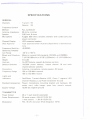
SPECIFICATIONS
GENERAL
Channels
: Transmit
Receive
55
55
Frequency Control
Method
: PLL synthesizer
Antenna Impedance:
50 ohms, nominal
Speaker
: 2.85 Inch, 8 ohms
Microphone
: Rugged 600 ohms dynamic element with coiled cord and
plug-in connector
LED numerical read out
Channel Display
DOC Approval
: Type approved under Australia Department of Communications
::\:0.0005%
Frequency Stability:
Operating Tempera0
0
ture Range
: -20 C to +50 C
Shock and Vibration:
Meets or exceeds EIA standards', RS152A and RS204A
Size
: 7-1/4"W(185m/m) x 9-7/8"L(250m/m) x 2-1/4"H(58m/m)
Weight
: 4.5 LBS
Controls
: On-Off/Volume, squelch & dimmer controls
Selector Switches:
1W/25W power selector, Instant channel 16 and main
channel selector switches
Connectors
: Antenna, microphone, remote speaker, DC power
Frequency Range:
156 to 158 MHz transmit
156 to 163 MHz receive
Lights and
Indicators
Red/Green Transmit-Receive LED, Green 7 segment LED
Channel Readout, Low Power & Channel 16 LED
Standard Accessories: Plug-in microphone, mounting bracket and hardware, DC
power cord, mike hanger, spare fuse, owner's manual,
: 13.8V DC negative ground
Supply Voltage
TRANSMITTER
Power Output
:
Power Requirement:
Modulation
:
25 or 1 watt (switch selectable)
25 watts output: 4.5A @ 13.8V DC.
1 watt output:
1.OA @ 13.8V DC.
FM,::\:5 kHz deviation (FCC designator 16F3)
-2-
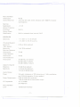
--,~
Hum and Noise
Attenuation
Audio Distortion
Spurious
Suppression
Output Transistor
Protection
Output Power
Stabilization
-_.
---
: 45 dB
:
Less than 5% with 3 kHz deviation with 1000 Hz modulating frequency
:
-70 dB
:
Built-in
:
Built-in automatic level control (ALC)
:
-117 dBm for 12 dB SINAD
-114 dBm for 20 dB quieting
RECEIVER
Sensitivity
Threshold Squelch
Sensitivity
Tight Squelch
Sensitivity
Spurious Response
Attenuation
Image Response
Attenuation
Intermodulation
Attenuation
Adjacent Channel
Rejection
Selectivity
: 0.20 J.1V(E lA method)
: 2 J.1V(E lA method)
:
75 dB
:
75 dB
: 70 dB @ 0.3 J.1Vdesired
50 dB @ 30 J.1Vdesired
35 dB @ 300 J.1Vdesired
: 70 dB (EIA method)
: :17.5 kHz @ 6 dB down
:115 kHz @60 dB down
Audio Output
Power
: 3.5 watts minimum at 10% distortion at 1 kHz modulation
and :13.5 kHz deviation (4 ohm speaker)
Power Requirement:
0.6A @ 13.8V DC, squelched
1.2A @ 13.8V DCat rated audio output
: 1st--21.4 MHz
IF Frequencies
2nd--455 kHz
Hum and Noise
Level
: -50 dB (EIA method)
-3-
=r
~-
~
::
I"'..."...
:::::::::=,~-:
'
INSTAllATION
CAUTION: The MC480 will operate only with nominal 12 volt negative
ground battery systems.
It is important to carefully determine the most suitable location for your MC480
on your vessel. Electrical, mechanical, and environmental considerations must all be
taken into account. You must select the optimum relationship among these considerations.
Keep in mind the flexibility designed into the MC480 so that you can most conveniently use your radio. Features which should be considered are:
1. Universal mounting bracket may be installed on either top or bottom for shelf,
bulkhead, or overhead mounting.
2. The microphone connector face forward allowing convenient in-dash or "builtin" installations.
3. The front panel can be fully reversed to provide for optimum viewing and
operating for any mounting position. (See page 5)
4. The REMOTE speaker jack may be used with an auxiliary speaker.
All connections are "plug-in" type for easy removal of the radio.
-4To
-'
~
'._-1-
,.
!
===:
-==
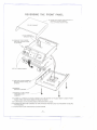
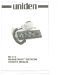
REVERSING THE FRONT PANEL
(2) TURN UNIT OVER AND CAREFULLY
REMOVE COVER CABINET
PULL UP FROM REAR FIRST.
(5) REMOVE TWO SCREWS
HOLDING FRONT PANEL.
TO CHASSIS.
(6) TI LT FRONT PANEL.
(7) REPLACE FOUR SCREWS TO
SECURE FRONT PANEL TO
CHASSIS.
(4) REMOVE
SPEAKER CABINET.
(1) REMOVE FOUR SCREWS
FROM SPEAKER
CABINET.
(8) CAREFULLY REPLACE COVER CABINET BUT ON BOTTOM OF RADIO INSERT UNDER FRONT
PANEL FIRST AND THEN LOWER AT REAR OF RADIO.
(9) TURN RADIO OVER AND RECONNECT SPEAKER WIRE LEADS.
(10) REPOSITION SPEAKER CABINET ON TOP OF RADIO AND REPLACE FOUR SCREWS TO SECURE
THE HOUSING.
(11) RETIGHTEN FOUR APPEARANCE COVER SCREWS.
-5-
T
~
-r--..
.-'--
J-..-
".-.---.
.-...-.-...-------")
Some of the more important external factors to consider in selecting the location of
your MC480 are:
1. Select a location that is free from spray and splash.
2. Keep the battery leads as short as possible. Connection directly to the battery is
most desirable. If direct connection cannot be made with the supplied power
lead, any extension should be made with #10 AWG wire. Long extensions
should use larger wire.
3. Keep the antenna lead as short as possible. Long antenna leads can cause substantial loss of performance for both receiving and transmitting.
4. Locate your antenna as high as possible and clear from metal objects. The
reliable range of coverage is a direct function of antenna height.
5. Select a location that does not allow the radio to be subjected to direct sunlight
(including that coming through windows).
6. Select a location that allows free air flow around the heat sink on the rear of the
radio.
7. Select a location well away from the ship's compass. Auxiliary speakers also
should be located away from the compass.
After you have carefully considered the various factors affecting your choice of
location, position the radio (with the bracket, microphone, power plug, antenna
plug, and any auxiliary plugs installed) into the selected location to assure there is
no interference with surrounding items. Make the location of the mounting bracket.
Remove the bracket from the radio and use it as a template to mark the holes to be
drilled for the mounting hardware. Drill the holes and mount the bracket with
hardware compatible with the material of the mounting surface. Install the power
cable (red is +, black is -), antenna and all other auxiliary cables and accessories.
Install the radio into the mounting bracket and connect all cables and accessories to
the appropriate jacks and connectors.
ANTENNA
A variety of antennas are available from a number of quality suppliers. It is
recommended you draw upon the advice of your UNIDEN Dealer in determining a
suitable antenna for your vessel and range requirements.
The general rules for antennas are: The more gain the greater the range and, the
higher above the water line the greater the range. Antennas should be located so as
not to be in proximity to metal objects. Antennas should not have excessively long
coaxial feed cables.
-6-
-~
--'-""
,~~".-
ENGINE NOISE SUPPRESSION
Interference from the impulse noise generated by the electrical systems of engines is
sometimes a problem with radios. The MC480 has been designed to be essentially
impervious to ignition impulse noise and alternator noise. However, in some
installations it may be necessary to take measures to further reduce the effect of
noise interference. All DC battery wires, antenna lead, and accessory cables should
be routed away from the engine and engine compartment and from power cabling
carrying particularly high currents.
In severe cases of impulse noise interference, it may be necessary to install a noise
suppression kit that is available from your UNIDEN Dealer.
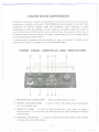
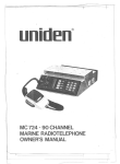
FRONT PANEL CONTROLS AND INDICATORS
cv
CID
@ CV@
CD
@
@@@
@
1. MICROPHONE CONNECTOR. . . Plug your Microphone in here.
2. ON/OFF VOLUME KNOB. . . is used to turn on the radio and set the volume
to a comfortable level.
3. SQUELCH KNOB... is used to quiet background noise when no signal is
being received. Turn the knob just past the point at which background noise is
objectionable.
4. CHANNE L SE LECTOR. . . is used to select the desired channel. The channel
is displayed by the LED readout.
-7-
=c
I~
H"""
".~.~._.__.-
~
~
--""">~~
-;:;.~.
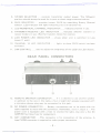
5. 1W/25W SELECTOR. . . controls transmitter output power. The 1W(watt)
position should always be used for in-port or short range communications.
6. CH16 SELECTOR...
selector. LED indicator
provides instant CH16 by overriding Rotary
will light indicating unit is on Channel 16.
7. LED NUMERICAL CHANNEL INDICATOR..
Channel
. indicates channel in use.
8. TRANSMIT/RECEIVE
LED INDICATOR...
indicates whether transmit or
receive mode is in use. (Red for transmit, Green for receive.)
9. LOW POWER LED INDICATOR...
power (1 watt).
shows when unit is switched to Low
10. CHANNEL 16 LED INDICATOR.
activated.
. . lights to show CH16 switch has been
11. DIM CONTROL. . . used to adjust the brightness of the LED's & LED display.
REAR PANEL CONNECTORS
I
I
I
@
@
@
12. REMOTE SPEAKER CONNECTOR. . . If it is desired to use another speaker
in addition to the one in the radio, a four or eight ohm speaker equipped with
a miniature phone plug may be connected to this jack.
13. DC POWER CONNECTOR. . . Battery connections
cable
supplied
to mate with this connector.
Remember,
are to be made with the
red is +, black is
-. The
power cord is equipped with a fuse to protect the radio. Use only a Six (6)
AMPERE fast blow fuse for replacement.
14. ANT CONNECTOR. . . This connector
type PL259 connector
is required
-8-
!
is for connection
to make proper connection.
of the antenna. A
~
.....
~
Ii:
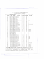
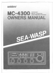
VHF FM MARINE RADIOTELEPHONE
CHANNELS AND FUNCTIONS
(INTERNATIONAL
CHANNEL
DESIG
P1
02
03
04
05
06
07
08
09
10
11
12
13
14
15
16
17
18
19
20
21
22
23
24
25
26
27
28
60
61
62
63
64
65
66
67
68
69
70
71
72
73
74
77
78
79
80
81
82
83
84
85
86
87
88
CAUTION:
FREOUENCY(MHz)
SHIP
SHORE
157.375
157.375
156.100
160.700
156.150
160.750
156.200
160.800
156.250
160.850
156.300
156.300
156.350
160.950
156.400
156.400
156.450
156.450
156.500
156.500
156.550
156.550
156.600
156.600
156.650
156.650
156.700
156.700
156.750
156.750
156.800 156.800
156.850
156.850
156.900 161.500
156.950 161.550
157.000
161 .600
157.050
161.650
157.100
161.700
157.150
161.750
157.200
161.800
157.250
161.850
157.300
161.900
157.350
161.950
157.400
162.000
156.025
160.625
156.075
160.675
156.125
160.725
156.175
160.775
156.225
160.825
156.275
160.875
156.325
160.925
156.375
156.375
156.425
156.425
156.475
156.475
156.525
156.525
156.575
156.575
156.625
156.625
156.675
156.675
156.725
156.725
156.875
156.875
156.925
161.525
156.975
161.575
157.025
161.625
157.075
161.675
157.125
161.725
157.175
161.775
157.225
161.825
157.275
161.875
157.325
161.925
157.375
161.975
157.425
162.025
OPERATION
CHANNEL)
SHIP
SHIP
TO SHIP TO SHORE
Yes
Yes
Non
Yes
Yes
Port
Yes
Yes
Port
Yes
Yes
Port
Yes
Yes
VTS
No
Yes
S~fety
Yes
Yes
Com'l
No
Yes
Com'l
Yes
Yes
Com'l & Non Com'l
Yes
Yes
Com'l
Yes
Yes
Corn'!
Yes
Yes
Port Ops
Yes
Yes
Navigational
Yes
Yes
Port Ops
Yes
Yes
Envi ronmental
Yes
Yes
Safety Calling
Yes
Yes
State Control
Yes
Yes
Com'l
Yes
Yes
Com'l
Yes
Yes
Port Ops
Yes
Yes
Coast Guard
Yes
Yes
Coast Guard
Yes
Yes
Coast Guard
Yes
No.
Public Corresp.
No
Yes
Public Corresp.
No
Yes
Public Corresp.
No
Yes
Public Corresp.
No
Yes
Public Corresp.
TYPE
TRAFFIC
Corn'!
Ops
Ops
Ops
I
Port Ops
Port Ops
Corn'!
Non Com'l
Non Com'l
Non Com'l
Non Com'l
Non Com'l
Port Ops
Port Ops
Port Ops
Non Com'l
Corn'!
Com'l
Coast Guard
USGovOnly
CoastGuard
Public Corresp.
Public Corresp.
Public Corresp.
Public Corresp.
Com'l
ON CHANNELS
Yes
Yes
Yes
Yes
Yes
Yes
Yes
Yes
Yes
Yes
Yes
Yes
Yes
Yes
Yes
Yes
Yes
No
No
No
No
Yes
NOT
Yes
Yes
No
Yes
Yes
No
Yes
No
Yes
Yes
No
Yes
Yes
Yes
Yes
Yes
Yes
Yes
Yes
Yes
Yes
No
DESIGNATED
I
PERMANENT
SCAN LIST
Fish
Envi ronmental
Busy
Busy
Busy
Busy
Busy
Tel.
Tel.
Tel.
Tel.
Tel.
Fish
Fish
Fish
Fish
Fish
Coast Guard
CoastGuard
Busy Tel.
Busy Tel.
Busy Tel.
Busy Tel.
Busy Tel.
FOR
USE BY
YOUR CLASSIFICATION
OR CRAFT OR ON INTERNATIONAL
CHANNELS WHEN WITHIN AUSTRALIAN
TERRITORIAL -WATERS IS A
VIOLATION
OF DEPARTMENT
OF COMMUNICATION
RULES AND
REGULATIONS
AND MAY RESULT
IN SEVERE
PENALTIES.
-9- --------..
r-
~
~
c,.,
'.,
-'
"'"
~
,=
,,~~==>
~..-
~-_.
-
~
CARE AND MAINTENANCE
Your MC480 is a precision piece of electronic equipment and you should treat it
accordingly. Due to the rugged design, very little maintenance is required, however,
a few precautions should be observed.
If your radio has been accidentally subjected to spray or splash you should
immediately wipe it down with a soft cloth dampened with fresh water.
If the antenna has been damaged, you should not transmit except in case of
emergency. A defective antenna may cause damage to your radio.
You are responsible for the continued DOC technical compliance of your radio.
You are urged to arrange for periodic performance checks with your UNI DEN
Marine Dealer.
SERVICE
Should you find it desirable or necessary to have service performed on your MC480
you are urged to contact the UNIDEN Dealer from whom you made your purchase.
He, or any other UNIDEN Dealer, is able to provide you with complete service
performed by well qualified personnel.
If you require service that is within the terms of your warranty you should present
the validated WARRANTY CARD to your dealer to authenticate your claim. Your
WAR RANTY CARD is your passport to easy service! This card is to be completed
by your dealer at the time of purchase: Other suitable documents which clearly
establish ownership and date of purchase may be used in lieu of the WARRANTY
CARD.
If you find it inconvenient to have service performed by your local UNI DEN
Marine Dealer, you may also obtain service from the Factory Service Station. If you
require factory service, please pack your radio in a suitable container whic~ will
provide adequate protection, enclose a note describing the problem, and a copy of
your validated WARRANTY CARD or other proof-of-purchase document and
return (transportation prepaid) to:
Santronic Agencies Pty. Ltd.
13 Garema Circuit, Kingsgrove
Phone 758 1522
P.O. Box 12, Kingsgrove, NSW 2208
If the service you require is not within the terms of the warranty, you should
specifically include written authorization of proceed with service and to agree to
appropriate charges.
- 10-
-k
'-,
"
..
,...
)(M
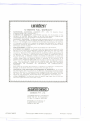
uniden@
12 MONTHS FULL WARRANTY
WARRANTOR.
SANTRONIC
AGENCIES
PTY.
LTD.
13 Garema Circuit,
Kingsgrove MSW 2208 ("SANTRONIC").
ELEMENTS
OF WARRANTY.
SANTRONIC
warrants, for the duration of this
warranty, its UNIDEN
Marine Product to be free from defects in materials and
craftsmanship with only the limitation or exclusions set out below.
~
....
~
:le
-,
~"
~
"
~
~:,
WARRANTY
DURATION.
This Warranty shall terminate and be of no further effect
On e (1) years after the date of original purchase of the Product or at the time the
Product is (a) damaged or not maintained as reasonable and necessary, (b) modified,
(e) improperly installed, (d) is repaired by someone other Warrantor for a defect or
malfunction covered by this Warranty, or (e) used in a manner or purpose for which
the Product was not intended.
PARTS COVERED.
This Warranty covers all components of the Products.
STATEMENT
OF REMEDY. In the event that the Product does not conform to this
Warranty at any time while this Warranty is effective, Warrantor will repair the defect
and return it to you prepaid, without charge for parts, service, or any other costs
incurred by Warrantor or its representatives in connection with the performance of
this Warranty. In addition, if the Product contains a defect or malfunction which is
not repaired after a reasonable number of attempts by Warrantor to repair the
Product, the Product or defective component will at our discretion, will be replace
without
charge, when the defective product is delivered to the warrantor
at 13
Garema Circuit Kingsgrove NSW 2208 free and clear of all liens and encumbrances.
Please note that while the Product will be remedied under this Warranty without
charge. THIS WARRANTY
DOES NOT COVER OR PROVIDE FOR THE RE'IMBURSEMENT
OR
PAYMENT
OF
INCIDENTAL
OR
CONSEQUENTIAL
DAMAGES.
Some states do not allow this exclusion or limitation of incidental or consequential
damages, so the above limitation or exclusion may not apply to you.
PROCEDURE
FOR OBTAINING
PERFORMANCE
OF WARRANTY.
In the event
that the Product does not conform to this Warranty, the Product should be shipped
prepaid to Warrantor at 13 Garema Circuits Kingsgrove NSW 2208. THE ORIGINAL
OR COpy OF THE SALES RECEIPT OR OTHER VALID EVIDENCE
OF THE
DATE OF THE ORIGINAL PURCHASE MUST ACCOMPANY THIS PRODUCT.
LEGAL
REMEDIES.
This Warranty
gives you specific
have other rights which vary from state to state.
legal rights, and you may also
Sanlronlc
AGENCIES
)
PTY. LTO.
13 GAREMA CIRCUIT, KINGSGROVE
PHONE 7581522, TELEX AA73170
P.O. Box 12, Kingsgrove, NSW2208
BRISBANE: 3/12 RANDALL ST
SLACKS CREEK, OLD 4127
PHONE 07 290 1188
UTSNO17860Z
@Copyright
1984 Uniden Corporation
Printed in Taiwan
,
r~
...-----------
1
,