1
'=
'-'
-
--.---.
.---- -
unid~n@
WASHINGTON CB RADIO
OWNERS MANUAL
'
--'-
'
'---'
'---
--
,-
~
1
--=------
r~
INTRODUCTION
UNIDEN CORPORATION OF AMERICA has combined superb workmanship and
modern styling with the very latest state of the art circuitry to bring you the new
~ASHINGTON Citizens Band Transceiver. It has been especially designed to give
you maximum performance and reliability. Your WASHINGTON is completely
factory aligned and quality assurance tested.
To obtain the maximum benefit and pleasure from your WASHINGTON, please read
very carefully the contents of this manual before attempting to install or operate the
transceiver.
WARNING
The Citizens Band (CB) Radio Service is under the jurisdiction of the Federal
Communications Commission (F .C.C.). Any adjustments or alterations which would
alter the performance of the transceiver's original F.C.C. Type Acceptance or which
would change the frequency determining method are strictly prohibited. Replacement or substitution of Crystals, Transistors, ICs, Regul~tor Diodes or any other part
of a unique, nature, with parts other than those recommended by us, may cause
violation of the technical regulations of Part 95 of the F.C.C. Rules or violation of
Type Acceptance requirements of Part 2 of the Rules.
ELIMINATION OF LICENSING
The Federal Communications Commission (F .C.C.) has ruled that Citizens Band (CB)
Radio Service operators no longer are required to obtain an F.C.C. license to operate
their CB equipment. In doing so, the F.C.C. also decided to permit CB station
operation without station identification.
Elimination of individual station licenses results in no lessening of the operating
privileges or responsibilities of CB users. An operator of a CB radio station is still
required to comply with the Communications Act and with the rules of CB Radio
Service. .
WARNING - TO. PREVENT FIRE DR SHDCK HAZARD, DD NDT
EXPDSE THIS APPLIANCE TO. RAIN DR MOISTURE.
-1-
=t
:
J
-.
-
I
- -, -
.
..-
.
. . .-.
...
...;
=l
--
-----J-.
~
r
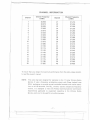
CHANNEL INFORMATION.
Channel
Channel Frequency
in MHz
Channel
Channel Frequency
in MHz
1
2
3
4
5
6
7
8
9
10
11
12
13
14
15
16
17
18
19
20
26.965
26.975
26.985
27.005
27.015
27.025
27.035
27.055
27.065
27.075
27.085
27.105
27.115
27.125
27.135
27.155
27.165
27.175
27.185
27.205
21
22
23
24
25
26
27
28
29
30
31
32
33
34
35
36
37
38
39
40
27.215
27.225
27.255
27.235
27.245
27.265
27.275
27.285
27.295
27.305
27.315
27.325
27.335
27.345
27.355
27.365
27.375
27.385
27.395
27.405
To insure that you obtain the maximum performance from this radio, please carefully read this owner's manual.
NOTE:
This radio has been designed for operation in the 11 meter Citizens Radio
Service. It uses a frequency synthesizing circuit with Phase Locked Loop
(PLL) techniques to provide crystal controlled transmit and receive operation on all 40 channels. The PLL circuitry assures ultraprecise frequency
control. It is designed to meet the Federal Communications Commission
requirements applicable to equipment operating in the Citizens Radio
Service, and is not to be used for any other' purpose.
-2-
=:f
..~
-r-
f
-
-- . ----
f=
._._._-
INSTAllATION
Location
Prior to begining operation of the transceiver, a basic installation must be done.
Installation of the transceiver itself is a rather simple procedure.
In selecting the location for the unit, two factors must be considered:
~v
1. Access to a ~
AC, 60Hz power source for your BASE STATION installation.
Be sure to connect the AC power cord to an AC power source, not to a DC power
source.
2. The location must be convenient for running the antenna lead-in cable to your
transceiver.
BASE STATION ANTENNA
Since th'e maximum allowable power output of the transmitter is limited by the
F.C.C., the antenna is the most important factor affecting transmission distance.
Only a properly matched antenna system will allow maximum power transfer from
the 52 Ohm transmission line to the radiating element.
The recommended method of antenna tuning is to use an in-line watt-meter or VSWR bridge to adjust the antenna for minimum reflected power on channel 19.
The radio may be used with any type of 52 Ohm base station antenna. A ground
plane vertical antenna will provide the most uniform horizontal coverage. This type
of antenna is best suited for communication with a mobile unit. For point-to-point
operation where both stations are fixed, a directional beam will usually increase
communicating range since this type of antenna concentrates transmitted energy in
one di-rection. The beam antenna also allows the receiver to "listen" in only one
direction thus reducing interfering signals.
Antenna height is an important factor when maximum range is desired. Keep the
antenna clear of surrounding structures or foliage. F.C.C. regulations limit antenna
height to 20 feet above an existing structure.
MOBILE OPERATION/EMERGENCY
POWER OPERATION
It is possible to operate the WASHINGTON from an external 13.8V DC power
supply for emergency power conditions or from an automobile battery for mobile
operation. The WASHINGTON is supplied with a polarized plug for operation with
an external DC su pply .
Negative lead is black.
Positive lead is red and has the in-line fuse holder as an integral part of the
positive lead.
~3-
t
--,-, -
~
--
r
-----
r--
t
...
-«-
c
,
<-<
<-<.
...<-
PUBLIC ADDRESS
An external 8 Ohm, 4 watt speaker may be connected to the PA speaker jack located
on the rear panel when the transceiver is used as a public address system. The speaker
should be directed away from the microphone to prevent acoustic feed-back.
Physical separation or isolation of the microphone
operating the PA at high output levels.
and speaker must be used when
REMOTE SPEAKER
The external speaker jack (EXT. SPKR.) on the rear panel is used for remote receiver
monitoring.
The external speaker should have 8 Ohms impedance-and be able to
handle at least 4 watts.
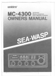
RADIO BACK PANEL CONNECTORS
~
@
~~~~
~~~~
~~~~
~~~~
~~~~
~~~~
Q)
@i)
13.8V DC
+
FUSE
AC/DC Switch
ANTENNA eonnector
DC POWERCord Jack
EXTERNAL SPEAKER Jack
120V AC 60Hz
FUSE
\
AC POWER Cord
I
IMPORTANT!
The above illustration shows the location of the various accessory,
antenna, and power receptacles, as well as the SERIAL NUMBER.
You are urged to record your model number and your SERIAL
NUMBER in the spaces provided below:
Model
SERIAL NUMBER
-4-
==.f
---..
-1
----
~-
--
--
.-----
~
OPERATING
PROCEDURE
TO RECEIVE:
The WASHINGTON operates on 40 AM channels,40 Upper Side Band channels and
40 Lower Side Band channels.
When you receive the SSB signal in the proper mode, audio sound may be either too
high pitched, or Iow pitched, indicating that your receiver may not be tuned to the
exact same frequency as the transmitter it is listening to. The WASH INGTON is
equipped with a Clarifier. By tuning the Clarifier, you can slightly
quency of the receiver. $0, you can get a normal tone.
change the fre-
1.
Turn the SQUELCH control clockwise until click is heard, do not advance too
far or you will not hear any background noise. Advance the R F GAl N control
fully clockwise.
2.
Turn the set on by turning the VOLUME
CONTROL
clockwise, past click.
NOTE: Microphone must be plugged in for the receiver to operate.
3.
Set the VOLUME
CONTROL
to a comfortable
level.
4.
Set the Mode Selector Switch to the desired mode.
5.
Listen to t~e background noise from the speaker. Turn the SQUELCH CONTROL slowly clockwise, until the noise just disappears. The Squelch is now properly adjusted. The receiver will remain quiet until a signal is received. Do not
advance the control too far, or some of the weaker signals will not be heard.
6.
Set 1he Channel Selector to the desired channel.
7.
Adjust the CLARIFIER
to clearly receive SSB or AM signals.
TO TRANSMIT:
CAUTION
The transmitter Voltage Standing Wave Ratio (V.S.W.R.) measurementmust be
performed prior to the use of the transmitter. A.V.S.W.R. ratio in excess of
2: 1 may damagethe transmitter.
1.
Be sure the operator has read and understands part 95, F .C.C. Rules and Regulations prior to operating the transmitter.
2.
Select the desired channel.
3.
If the channel is clear, depress the push-to-tqlk
speak in a normal voice.
switch on the microphone
and
-5-
==f
---_.-
~
I-I
~
,
:=
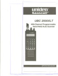
CONTROLS AND THEIR
FUNCTIONS
0
.
unlden 0
~'OR'
@ J~ JJ M(6)N ~NA'@S.C~R 999:
1. ON/OFF VOLUME CONTROL: To turn the transceiver on, rotate the control
clockwise past click. To turn the transceiver off, rotate the control counterclockwise past click. Rotate the control for a comfortable audio level.
2. CHANNEL SELECTOR: This switch is used to select anyone of the 40 Citizens
Band channels. Channel 9 has been reserved by the F.C.C. for emergency communications involving the immediate safety of life of individuals or immediate
protection of property. Channel 9 may also be used to render assistance to a
motorist.
3. CHANNEL 9 SWITCH: This switch is for use when emergency communications
is needed on the emergency channel, CH9. Pressing the CH9 switch activates
CH9 regardless of the position of the channel selector switch. When CH9 switch
is pressed, the channel display is blanked and the CH9 indicator is activated.
4. MODE SELECTOR: This switch selects AM, USB, or LSB mode of operation.
This selector changes the mode of operation of both transmitter and receiver
simultaneously. Set the selector to the mode on which you desire to communicate.
5. SQUELCH: The squelch control is normally set to a position which eliminates
undesired background noise with no signal present. With the audio adjusted to a
satisfactory level, rotate the Squelch control clockwise to the point where the
sound from the speaker is cut off. In this position, there will be no sound from
the speaker until a signal is received. In order to hear weak signals, it may be
necessary to rotate the Squelch control counterclockwise, allowing some background noise to be heard.
-6-
r
=t
1
--
-
r
----1
~
<:::;
6. PA(Public Address) SWITCH: To engage the PA function, rotate the SQUELCH
control counterclockwise
past click. Press the press-to-talk switch on the
microphone and speak in the microphone in a normal voice level. The PA
function should not be used unless the PA speaker is connected.
7. MIC GAIN: This control is used to adjust, as required, microphone
sensitivity for the optimum amount of modulation in transmit.
input
8. RF GAIN: This control is used primarily to optimize reception in strong signal
areas. Gain is reduced by counterclockwise rotation of the control.
9. CLARIFIER: The clarifier is normally set to the center position. This feature
has several uses and can greatly enhance receiver operation. If a received signal is
slightly off frequency, th is control can be operated to optimize the received
signal. This control is primarily intended to tune in SSB signals, but it may also
be used to optimized the AM signal.
10. NB/ANL SWITCH: When the switch is placed in the NB/ANL position, the RF
Noise Blanker and Automatic Noise Limiter circuits are activated. The Noise
Blanker cut out annoying impulse-type noise such as ignition noise on both AM
and SSB modes. The Automatic Noise Limiter reduces most undesirable interference noises.
INDICATOR FUNCTION
1.
S/RF PWR METER: When the transceiver is in the receive mode, relative signal
strength is indicated in S units on the lower scale of the meter. When transmitting, relative power output is indicated on the upper scale of the meter. When
the MOD-SIR F switch is depressed, the meter indicates modulation percentage.
2. TX/RX INDICATOR: This indicator lights in red when the transmitter is in
operation and lights in green when receiver is in operation.
3. MODE INDICATOR: This radio is equipped with mode indicator lights for AM,
USB and LSB modes. When you set the mode selector to the mode desired, the
related indicator light comes on.
4.
CH9 INDICATOR: This indicator lights when the CH9 switch is depressed.
HEADPHONE
This radio is provided with.a headphone jack for private listening. To use this feature,
just plug the headphone plug into the jack labeled "PHONE" on the front panel.
-7-
=t
r
-------------.----------.--..
---
-
!I
-.- "-
--
,---~
t
I
-
-====
,.
-+-
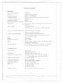
SPECIFICATIONS
GENERAL
F.C.C. Type Number
1001 002
Channels
40 AM, 40 LSB, 40 USB
Frequency Range
26,965 to 27,405 MHz
Frequency Control
Frequency Tolerance
Phase Locked Loop(PLL)
Frequency Stability
Operating Temperature
Microphone
Range
Plug-in type; dynamic
coiled cord
117V AC nominal.
Input Voltage
Synthesized Circuitry.
0.0005% Typical
0.001%
-200 C to +500 C
with push-to-talk
switch and
13.8V DC nominal, (positive or negative ground)
Power Consumption(120V
Current Drain(13.8V
DC)
Size
Weight
Antenna Connector
Meters
AC)
Transmit: full mod., 75 watts.
Receive: squelched, 45 watts.
Transmit: 2.2A typical; 3A maximum.
Receive: squelched, 0.3A; full audio output,
5"H x 13%"W x 12"0
13.3 pounds.
UHF, SO-239
Shows relative
power
output
1A
and received signal
strength and modulation.
46 transistors, 1 field effect transistor, 6 integrated
circuits, 61 diodes and 6 light emitting diodes.
Semiconductors
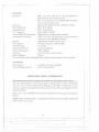
TRANSMITTER
AM, 4 watts
SSB, 12 watts, P.E.P.
Power Output
Modulation
Intermodulation
Distortion
SSB Carrier Supression
Unwanted Sideband
Frequency Response
Output Impedance
SSB Filter
Output Indicator
AM, high and Iow level Class B.
SSB: 3rd and 5th order, more than -25 dB.
7the and 9th order, more than -35 dB.
More than -45 dB
More than -45 dB
AM and SSB: 300 to 3000 Hz.
52 ohms, unbalanced
7.8 MHz, crystal lattice type
6 dB @ 4.2 KHz
60 dB @ 7.0 KHz
Meter shows relative
RF output
power.
-8-
t
J
--
r-
-----
f
I
<::-~~
,-
'"
RECEIVER
Sensitivity
Selectivity
Cross Modulation
Image Rejection
I.F. Frequency
AM and SSB R F Gain Control
Automatic Gain Control
,
SSB: Less than 0.25 /lV for 10 dB (S+N)/N at
greater than Y:zwatt of audio output.
AM: Less than 0.5 /lV for 10 dB (S+N)/N at greater
than Y:zwatt of audio output
SSB and AM: 6 dB @ 4.2 KHz, 60 dB @7.9 KHz
Better than -55 dB
Better than -60 dB
AM and SSB: 7.8 MHz
Squelch
Noise Blanker
Clarifier Range
Audio Output Power
Frequency Response
Distortion
Adjustable for optimum signal reception
(AGC): Less than 10 dB change in audio output for
inputs from 10 to 500,000 microvolts.
Adjustable; threshold less than .5/lV
RF type, effective on AM and SSB
:t1.25 KHz
4 watts into 8 ohms
300 to 2500 Hz
Less than 10% at 3 watts output
Built-inSpeaker
8 ohms
External Speaker (Not Supplied) 8 ohms, disables internal speaker when connected
PA SYSTEM
Power Output
External Speaker for PA
4.0 watts into External Speaker
8 ohms (not supplied)
SERVICING
YOUR TRANSCEIVER
TR8 T88RRie81iRfsl'FR8tisR, eia§r8FR58Re 8R8rt9 .;:ill 1389\!1~~1i8e\!I~SRr8~\!I96t. It is
the user's responsibility to see that this radio is operating at all times in accordance
with the F.C.C. Citizens Radio Service regulations. We highly recommend that you
consult a qualified radiotelephone technician for the servicing and alignment of this
CB radio product.
Please refer to the WARN ING information contained in the 1st page of this Owner's
Manual.
(NOTE: When ordering parts, it is essential to specify the correct model number and
serial number of the unit.)
-9-
=t
--------
-
r-----
f
,
<:::.
MAINTENANCE AND ADJUSTMENT
This transceiver is especially designed for the environment encountered in base
station installations. The use of all solid state circuitry and its light weight result in
high realiability. Should failure occur, however, replace parts only with identical
parts. Do not substitute.
PREVENTIVE MAINTENANCE
At six to twelve month intervals, the following system checks should be made:
1. Check Standing Wave Ratio (SWR).
2. Inspect all electrical connections to ensure that they are tight.
3. Inspect antenna coaxial cable for wear or breaks on shielding.
4. Inspect all screws and other mounting hardware for tightness.
ADJUSTMENT
This transceiver is factory aligned and should not require any adjustment when used
with a 52 ohm antenna. If an antenna other than 52 ohm impedance is used,
adjustment of the transmitter output circuit may be made to obtain optimum power
transfer to the antenna. This adjustment should be made only by a qualified person
,
using a high quality in-line RF wattmeter which will not produce standing waves
when inserted in the antenna cable.
OPERATOR TROUBLESHOOTING
Should be unit malfunction or not perform peroperly, the operator should perform
the procedures indicated below:
1. If the transceiver is completely inoperative.
* Check the power cord and fuse.
2. If trouble is experienced with receiving.
* Check ON/OFF VOLUME CONTROL setting.
* 8e su re SOU ELCH is adjusted properly. Is the radio over squelched?
* Check to see that the radio is switched to an operational mode.
3. If trouble is experienced with transmitting.
* Check to see that the transmission line (coaxial cable) is securely connected to
the ANTENNA CONNECTOR.
* 8e sure that the antenna is fully extended for proper operation.
* 8e sure that all transmission line {coaxial cable} connections are secure and free
of corrosion.
-10-
=t
g
--
r
r-
i
-------
f
I
;:::
~
unid~n
TWO-YEAR
WARRANTOR.
UNIDEN
CORPORATION
LIMITED WARRANTY
OF AMERICA
("UNIDEN")
ELEMENTS OF WARRANTY. UNIDEN warrants, for the duration of this warranty, its UNIDEN CB
Product to be free from defects in materials and craftsmanship with only the limitation or exclusions
set out below.
WARRANTY DURATION. This Warranty shall terminate and be of no further effect Two (2) years
after the date of original purchase of the Product or at the time the Product is (a) damaged or not
maintained as reasonable and necessary, (b) modified, (c) improperly installed, (d) is repaired by
someone other than Warrantor for a defect or malfunction covered by this Warranty, or (e) used in a
manner or purpose for which the Product was not intended.
PARTS COVERED.
This Warranty covers all components
of the Products.
STATEMENT OF REMEDY. In the event that the Product does not conform to this Warranty at any
time while this Warranty is effective, Warrantor will repair the defect and return it to you prepaid,
without charge for parts, service, or any other costs incurred by Warrantor or its representatives
in
connection with the performance
of this Warranty. In addition, if the Product contains a defect or
malfunction which is not repaired after a reasonable number of attempts by Warrantor to repair the
Product, the Product or defective component will, at your election, either be replaced without charge
or the purchase price for the Product will be refunded when 'the defective Product is delivered to
Warrantor free and clear of all liens and encumbrances.
Please note that while the Product will be
remedied under this Warranty without charge.
THIS WARRANTY
DOES NOT COVER OR PROVIDE
FOR THE REIMBURSEMENT
OR
PAYMENT OF INCIDENTAL OR CONSEQUENTIAL
DAMAGES.
Some states do not allow this exclusion or limitation
above limitation or exclusion may not apply to you.
of incidental
or consequential
damages, so the
WARRANTY
REGISTRATION
CARD. In order to facilitate the servicing of this Warranty by
Warrantor, the Warranty Registration Card should be returned to Warrantor. However, return of the
Warranty Registration Card is not a precondition of this Warranty, and this WarraAty will be observed
by Warrantor whether or not the Warranty Registration Card is returned, on the condition that other
satisfactory evidence of the date of the original purchase is provided by Warrantor.
PROCEDURE FOR OBTAINING PERFORMANCE
OF WARRANTY. In the event that the Product
does not conform to this Warranty, the Product should be shipped prepaid to Warrantor.
THE
ORIGINAL OR A COpy OF THE SALES RECEIPTOR OTHER VALID EVIDENCE OF THE DATE
OF THE ORIGINAL PURCHASE MUST ACCOMPANY THIS PRODUCT.
LEGAL REMEDIES. This Warranty gives you specific legal rights, and you may also have other rights
which vary from state to state.
This warranty is void outside
the United States of America.
unid~n@
CORPORATION
OF AMERICA
Personal Communications Division
4700 Amon Carter Boulevard
Fort Worth, Texas 76155
UTUDO1509AD
@ Copyright 1983 Uniden Corporation of America
t
Printed in the Philippines
1
----
---
--