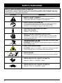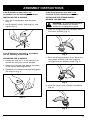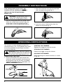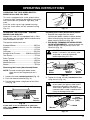
1
105r, 132r, & 137r
Electric Trimmers
OPERATOR’S MANUAL
FOR QUESTIONS, CALL 1-800-345-8746 in U.S. or
1-800-265-6778 in CANADA
www.ryobi.com
IMPORTANT MANUAL
DO NOT THROW AWAY
INTRODUCTION
THANK YOU
Thank you for purchasing this quality product.
This modern outdoor power tool is designed to
provide many hours of useful service. You will
find it to be a great labor-saving device.
This operator’s manual provides you with easyto-understand operating instructions. Read the
entire manual and follow all of the instructions
to keep your new outdoor power tool in top
operating condition.
The other manual that came with your power
tool, the parts manual, contains all of the
information that you need to order parts.
PRODUCT REFERENCES, ILLUSTRATIONS
AND SPECIFICATIONS
All information, illustrations and specifications
in this manual are based on the latest product
information available at the time of printing. We
reserve the right to make changes at any time
without notice.
Copyright © 1998 Ryobi Outdoor Products, Inc.
All Rights Reserved.
Click-Link® is a registered trademark of Ryobi
Outdoor Products, Inc.
SpeedSpool® is a registered trademark of Ryobi
Outdoor Products, Inc.
NOTE: PROOF OF PURCHASE WILL BE
REQUIRED FOR WARRANTY SERVICE.
TABLE OF CONTENTS
I.
Safety Warnings . . . . . . . . . . . . . . . . . . .3-6
A. Safety and International Symbols . . . . .6
II.
Assembly Instructions . . . . . . . . . . . . . . .7-8
A. Installing the D-Handle . . . . . . . . . . . . .7
B. Adjusting the D-Handle . . . . . . . . . . . . .7
C. Installing the String Guard
Models 105r and 132r . . . . . . . . . . . . . .7
D. Installing the String Guard
Model 137r . . . . . . . . . . . . . . . . . . . . . .8
III. Operating Instructions . . . . . . . . . . . . .8-10
A. Connecting the cord . . . . . . . . . . . . . . .8
B. Starting the trimmer . . . . . . . . . . . . . . . .8
C. Holding the trimmer . . . . . . . . . . . . . . . .8
D. Operating two-speed switch
Models 132r and 137r . . . . . . . . . . . . . .9
E. Operating the Click-Link System . . . . . .9
F. Adjusting the trimming line length . . . . .10
G. Decorative trimming . . . . . . . . . . . . . .10
IV. Maintenance and Repair Instructions .11-14
A. Line installation . . . . . . . . . . . . . . . . . .11
B. Winding the existing reel . . . . . . . . . . .11
C. Cleaning the SpeedSpool® . . . . . . . . .12
D. Installing a prewound reel . . . . . . . . . .13
E. Cleaning the trimmer . . . . . . . . . . . . . .14
V.
Specifications . . . . . . . . . . . . . . . . . . . . .14
VI. Troubleshooting . . . . . . . . . . . . . . . . . . . .14
VII. Notes . . . . . . . . . . . . . . . . . . . . . . . . . . . .15
THIS PRODUCT IS COVERED BY ONE OR MORE OF
THE US PATENTS: 5,076,149; 4,779,405; 4,651,422;
4,505,040; 4,463,498; 4,369,742; 4,342,236; 4,223,441;
2,125,688; D-249,012; D-239,329; OTHER PATENTS
PENDING.
SERVICE INFORMATION
Service on this unit both within and after the
warranty period should be performed only by
an authorized and approved service dealer.
Dial 1-800-345-8746 in the United States and
1-800-265-6778 in Canada to obtain a listing
of the authorized service dealer nearest you.
Do not return the unit to the retailer.
2
VIII. Warranty . . . . . . . . . . . . . . . . . . . . . . . . .16
Make sure this manual is carefully read and
understood before starting or operating this
equipment.
CONTENTS OF CARTON
This carton includes the following:
1. For completely assembled models:
• Trimmer
• Operator’s manual
• Owner’s registration card
2. For unassembled models - hardware pack
containing:
• D-Handle and hardware
• String guard and screws
• Operator's manual
• Owner’s registration card
SAFETY WARNINGS
THE PURPOSE OF SAFETY SYMBOLS
IS TO ATTRACT YOUR ATTENTION TO
POSSIBLE DANGERS. THE SAFETY
SYMBOLS, AND THE EXPLANATIONS
WITH THEM, DESERVE YOUR CAREFUL
ATTENTION AND UNDERSTANDING.
THE SAFETY WARNINGS DO NOT BY
THEMSELVES ELIMINATE ANY DANGER.
THE INSTRUCTIONS OR WARNINGS THEY
GIVE ARE NOT SUBSTITUTES FOR PROPER
ACCIDENT PREVENTION MEASURES.
SYMBOL
MEANING
SAFETY ALERT SYMBOL:
Indicates danger, warning or
caution. May be used in conjunction
with other symbols or pictographs.
NOTE: Advises you of information or
instructions vital to the operation
or maintenance of the equipment.
DANGER: Failure to obey a
safety warning will result in serious
injury to yourself or to others.
Always follow the safety precautions
to reduce the risk of fire, electric
shock, and personal injury.
WARNING: Failure to obey a
safety warning can result in serious
injury to yourself or to others.
Always follow the safety precautions
to reduce the risk of fire, electric
shock, and personal injury.
CAUTION: Failure to obey
a safety warning may result in
property damage or personal injury
to yourself or to others. Always
follow the safety precautions to
reduce the risk of fire, electric
shock, and personal injury.
• IMPORTANT SAFETY INFORMATION •
WARNING: When using electric
gardening appliances, basic safety
precautions should always be
followed to reduce the risk of fire,
electric shock, and personal injury.
Carefully read and understand the
entire Operator's Manual before
using your trimmer. Pay close
attention to the Operating
Instructions and Safety Warnings.
READ ALL INSTRUCTIONS
ELECTRICAL SAFETY WARNINGS
• This tool is double-insulated. Use only identical
replacement parts when servicing. Repair or
replace damaged cords.
• WARNING: To reduce the risk of electrical
shock, use only extension cords approved for
outdoor use, such as an extension cord of
cord type SW-A, SOW-A, STW-A, STOW-A,
SJW-A, SJOW-A, SJTW-W or SJTOW-A. A 2wire extension cord (an extension cord without
a ground) may be used because the tool is
double insulated. However, a 3-wire extension
cord (an extension cord with a ground) that
uses a NEMA type connector (parallel blade,
U ground) may also be used. Extension cords
are available from your local retailer. Use only
round-jacketed extension cords approved for
outdoor use.
• To reduce the risk of electrical shock, this unit
has a polarized plug (one blade is wider than
the other) and will require the use of a
polarized extension cord. This unit plug will fit
into a polarized extension cord only one way.
If the plug does not fit fully into the extension
cord, reverse the plug. If the plug still does not
fit, obtain a correct polarized extension cord.
A polarized extension cord will require the use
of a polarized wall outlet. This plug will fit into
a polarized wall outlet only one way. If the plug
does not fit fully into the wall outlet, reverse
the plug. If the plug still does not fit, contact a
qualified electrician to install the proper wall
outlet. Do not change the unit plug, extension
cord receptacle, or extension cord plug in any
way.
• Ground Fault Circuit Interrupter (GFCI)
protection should be provided on the
circuit(s) or outlet(s) to be used for this unit.
Receptacles are available having built-in
GFCI protection and may be used for this
measure of safety.
3
SAFETY WARNINGS
• CORD SETS: Make sure your cord set is in
good condition. When using a cord set, be
sure to use a cord that is heavy enough to
carry the current that your unit will draw. An
undersized cord set will cause a drop in line
voltage resulting in loss of power and
overheating. The table shows the correct size
to use depending on the cord length and
nameplate amperage rating. If in doubt, use
the next heavier size line gauge. The smaller
the gauge number, the heavier the cord. To
reduce the possibility of disconnection of the
unit cord from the cord set during operation,
see Fig. 9.
MINIMUM WIRE SIZE FOR EXTENSION CORDS
FOR 120 VOLT APPLIANCES USING 0-6 AMPS
Cord length (ft)
25
50
100
150
Wire size (AWG)
16
16
16
14
• A nameplate on your unit indicates what
voltage it uses. Never connect the unit to an
AC voltage that differs from this voltage.
• Inspect all extension cords and the unit
power connection periodically. Look closely
for deterioration, cuts or cracks in the
insulation. Also inspect the connections for
damage. Repair or replace the cords if any
defects appear.
• Avoid dangerous environments. Never
operate your unit in damp or wet conditions.
Moisture is a shock hazard.
• Do not use the unit in the rain.
• Do not handle the plug or the unit with wet
hands.
BEFORE OPERATING
• Read the instructions carefully. Be familiar
with the controls and proper use of the unit.
• Children and adolescents must not
manipulate units, except for adolescents in
training and under the supervision of a
specialist.
• Before each use, check that the cutting head
is correctly fixed and that the trigger returns
automatically in neutral position.
4
• Thoroughly inspect the trimmer for loose or
damaged parts before each use. Do not use
until adjustments or repairs are made.
• All guards and safety attachments must be
installed properly before operating the unit.
• Use the unit only in daylight or good artificial
light.
• Keep all bystanders, especially children and
pets, at least 30 feet (9.2 m) away from the
unit during operation.
• Before starting, adjust the handle to your size
and make sure that the cutting head is not in
contact with anything.
• Be aware of the risk of injury to the head,
hands and feet.
• Carefully inspect the areas to be cut. Remove
all debris that could become entangled in the
string or blade. Also remove any objects that
could be thrown during cutting.
WHILE OPERATING
• Use the right tool. Do not use this trimmer for
any job except that for which it is intended.
• Avoid accidental starting. Do not carry
plugged-in unit with your finger on the
switch. Be sure switch is off when
plugging in.
• Do not abuse the power cord. Never carry
the unit by the cord or yank the plug out of
the receptacle. Keep the cord away from
heat, oil and sharp edges.
• Always remain alert. To prevent injury to
yourself and others, do not operate this
trimmer if you are fatigued.
• Do not operate the unit while under the
influence of drugs, alcohol or medication.
• Wear safety glasses or goggles at all times
when operating this trimmer.
• Use a face mask or dust mask if operation is
dusty.
• Do not overreach. Keep proper footing and
balance at all times.
• Dress properly. Do not operate this trimmer
when barefoot or wearing open sandals.
Always wear sturdy, rubber-soled footwear.
The use of gloves, ear/hearing protection
and long pants are recommended.
SAFETY WARNINGS
• Do not wear loose fitting clothing or articles
such as scarves, strings, chains, ties, etc.,
because they could get caught in moving
parts. Also make sure long hair does not get
caught in moving parts. Long hair must be
pulled back and secured off shoulders and
neck.
• Keep hands, face, and feet away from all
moving parts. Do not attempt to touch or
stop the string when it is rotating.
• Always hold the trimmer with both hands
when operating. Keep a firm grip on both
the front and rear handles or grips.
• Frequently inspect the condition of the
cutting head. All damaged parts must be
replaced immediately. Follow all the required
precautions when undertaking replacement.
• If you strike or become entangled with a
foreign object, stop the engine immediately
and check for damage. Repair any damage
before further operation is attempted. Do
not operate the trimmer with loose or
damaged parts.
• Do not operate the unit faster than the speed
necessary to cut, trim or edge. Do not run
the unit at high speed when not cutting.
• Do not force the unit. It will do the job better
and with less likelihood of a risk of injury at
the rate for which it was designed.
• The string guard must be in place at all
times while operating the trimmer. Failure
to use the string guard may cause the unit
to overheat. DO NOT OPERATE WITHOUT
THE GUARD IN PLACE.
• Do not extend the trimming line beyond the
length of the guard specified in this manual.
• Do not operate trimmer without both
trimming lines extended, and the proper
line installed.
• Never use metal-reinforced or monofilament
line that is not specifically designed for use
with your model.
• Keep trimmer clean of vegetation and other
materials.
• Always stop the unit when cutting is delayed
or when walking from one cutting location
to another.
• All interventions, whether for maintenance,
repair or for changing cutting head or safety
attachments, must be undertaken with the
unit disconnected from the power supply.
• Use only genuine replacement parts when
servicing this trimmer. These parts are
available from your authorized dealer.
The use of non-standard parts, or other
accessories or attachments not designed for
this trimmer, could result in serious injury to
the user or damage to the trimmer and void
your warranty.
OTHER SAFETY WARNINGS
• Disconnect the unit from the power supply
when not in use, before servicing, when
changing accessories such as cutting head,
and the like.
• Maintain trimmer with care. Keep the unit
clean and serviced for the best and safest
performance. Follow the maintenance
instructions. Always use a clean cloth when
cleaning. Never use strong detergents,
gasoline, petroleum-based products, or any
strong solvents to clean the unit.
• Keep your unit in good working condition.
Follow instructions for servicing and
changing accessories. Inspect unit
periodically, and if damaged, have it repaired
by an authorized service facility. Inspect
extension cords periodically and replace if
damaged. Keep handles dry, clean, and free
from oil and grease.
• Store unit indoors. When not in use,
appliances should be stored indoors in a dry,
and high or locked-up place, out of the reach
of children.
• Keep these instructions. Refer to them
frequently and use them to instruct other
users. If you loan someone this unit, also
loan them these instructions.
SAVE THESE INSTRUCTIONS
5
SAFETY WARNINGS
SAFETY AND INTERNATIONAL SYMBOLS
This operator's manual describes safety and international symbols and pictographs that may
appear on this product. Read the operator's manual for complete safety, assembly, operating
and maintenance and repair information.
SYMBOL
MEANING
• SAFETY ALERT SYMBOL
Indicates danger, warning, or caution. May be used in
conjunction with other symbols or pictographs.
• READ OPERATOR'S MANUAL
Failure to follow operating instructions and safety precautions
in operator's manual can result in serious injury. Read
operator's manual before starting or operating this unit.
• FOR SERVICE INFORMATION CALL:
USA: 1-800-345-8746
CANADA: 1-800-265-6778
• WEAR EYE AND HEARING PROTECTION
WARNING: Thrown objects and loud noise can cause severe
eye injury and hearing loss. Wear eye and hearing protection
when operating this unit.
• THROWN OBJECTS AND ROTATING CUTTER CAN
CAUSE SEVERE INJURY
WARNING: Do not operate without guard in place. Keep away
from rotating cutter.
• KEEP BYSTANDERS AWAY
WARNING: Keep all bystanders, especially children and pets,
at least 30 feet (9.2 m) away from the trimming area.
• SHARP BLADE
Sharp blade on guard! Can cause injury. Do not touch blade.
• SPEED SWITCH OR THROTTLE SWITCH
Indicates “HIGH” or “FASTEST” speed.
• SPEED SWITCH OR THROTTLE SWITCH
Indicates “LOW” or “SLOWEST” speed.
6
ASSEMBLY INSTRUCTIONS
If the D-Handle on your unit is not
assembled, use the following instructions.
If the string guard on your unit is not
installed, use the following instructions.
INSTALLING THE D-HANDLE
INSTALLING THE STRING GUARD MODELS 105r AND 132r
1. Push the D-Handle down over the boom
(Fig. 1).
2. Install the bolt, washer, and wing nut, and
tighten (Fig. 2).
WARNING: To avoid serious personal
injury, never operate the trimmer
without the string guard in place.
1. Place the string guard onto the boom above
the clamp assembly (Fig. 3).
Fig. 1
If the D-Handle on your unit is assembled,
use the following instructions.
ADJUSTING THE D-HANDLE
1. Loosen the wing nut. It is not necessary to
remove the wing nut, washer and bolt.
Fig. 3
2. Push the string guard down to the top of the
string head assembly and then rotate the
string guard to the proper position (Fig. 4).
2. Rotate the D-Handle 180º (top of the boom)
to the correct operating position.
3. Position the D-Handle as desired and tighten
the wing nut (Fig. 2).
Fig. 4
3. Install the screws with a Phillips screwdriver
(Fig. 5).
Fig. 2
Fig. 5
7
ASSEMBLY INSTRUCTIONS
If the string guard on your unit is not
installed, use the following instructions.
2. Place the three hex nuts into the recessed
holes on top of the guard (Fig. 7).
INSTALLING THE STRING GUARD MODEL 137r
WARNING: To avoid serious personal
injury, never operate the trimmer
without the string guard in place.
1. Slide the string guard onto the guard mount
above the string head assembly. Align the
screw holes in the string guard with the
screw holes in the string assembly (Fig. 6).
Fig. 6
Fig. 7
3. Install the screws into the holes from the
bottom of the guard (Fig. 8).
Fig. 8
OPERATING INSTRUCTIONS
This trimmer has been designed and built to
withstand normal use. It will provide many hours
of service provided the operating instructions
are closely followed.
WARNING: Always wear eye, hearing,
foot and body protection to reduce the
risk of injury when operating this unit.
CONNECTING THE CORD
STARTING THE TRIMMER
Squeeze the trigger to start the trimmer.
STOPPING THE TRIMMER
Release the trigger to stop the trimmer.
HOLDING THE TRIMMER
While operating unit, hold the trimmer as shown
in Fig. 10.
1. Use the cord hook when you connect the
extension cord to the power cord to prevent
disconnection (Fig. 9). Use only an outdoorapproved extension cord as specified in the
SAFETY WARNINGS section.
Fig. 9
8
Fig. 10
OPERATING INSTRUCTIONS
OPERATING THE TWO-SPEED SWITCH MODELS 132r AND 137r ONLY
This unit is equipped with a two-speed switch a powerful high speed for demanding yard work,
and a precision low speed for light-duty yard
work.
Push the switch up for high speed trimming.
Push the switch down for low speed trimming
(Fig. 11).
OPERATING THE CLICK-LINK® SYSTEM MODELS 132r AND 137r
Models 132r and 137r are equipped with a ClickLink System, which enables optional attachments
to be installed on this unit.
The optional attachments are:
Sweeper/Blower ........................................SB720r
Vacuum........................................................LV720r
Edger ..........................................................LE720r
Cultivator....................................................GC720r
Straight Shaft Trimmer ............ SS670r or SS725r
Tree Pruner..................................................TP720r
Snow Thrower ............................................ST720r
Hedge Trimmer ..........................................HS720r
Blower/Vacuum ..........................................BV720r
Blower ........................................................TB720r
Removing the Lower (Attachment) Boom
NOTE: To make removing the boom easier,
place the unit on the ground or on a
table.
Fig. 11
Installing the Lower (Attachment) Boom
1. Remove the hanger from the lower
(attachment) boom. Hold the release button
down while pushing the lower (attachment)
boom into the Click-Link (Fig. 13).
2. FOR BASIC TRIMMING OR USING OTHER
RYOBI ATTACHMENTS - Locate and lock the
release button into the primary hole in the
Click-Link (Fig. 13).
CAUTION: Make sure the release
button is locked in the primary hole
and knob is securely tightened
before operating this unit.
Upper
Boom
Release
Button
3. Tighten the knob securely clockwise before
using the unit (Fig. 14).
2. Push the release button in (Fig. 12).
3. Pull the lower boom straight out of the ClickLink (Fig. 13).
Release Button
CAUTION: All attachments are designed
to be used in the primary hole unless
otherwise indicated in the specific
attachment’s operator’s manual. If the
incorrect hole is used, it could result in
injury, or damage to the unit.
Trimming Head
Edging Hole (90˚)
Trimming
Head
Edging Hole
(180˚)
Guide
Recess
Knob
Lower
Boom
Fig. 13
1. Loosen the knob counterclockwise (Fig. 12).
Click-Link
Primary Hole
Click-Link
Fig. 12
If your unit is not assembled, or you have
more than one attachment, use the following
instructions:
Knob
Washer
Fig. 14
9
OPERATING INSTRUCTIONS
ADJUSTING THE TRIMMING LINE LENGTH
Your trimmer is equipped with a bump head,
which allows the operator to release more
trimming line without stopping the motor. As the
line becomes frayed or worn, additional line can
be released by lightly tapping the trimming head
on the ground (Fig. 15a - Models 105r and 132r;
Fig. 15b - Model 137r) while operating the
trimmer at high speed.
NOTE: Always keep the trimming line fully
extended. Line release becomes more
difficult as cutting line becomes shorter.
WARNING: Do not remove or alter
the lead cutting blade assembly.
Excessive line length will cause the
motor to overheat and may result in
serious personal injury.
DECORATIVE TRIMMING
Decorative trimming is accomplished by
removing all vegetation around trees, posts,
fences, etc. Use a 30-degree angle when
trimming with this method (Fig. 16a - Models
105r and 132r; Fig. 16b - Model 137r).
Fig. 15a
Fig. 16a
Fig. 15b
Each time the head is bumped, approximately
1 in (25.4 mm) of trimming line is released. A
blade in the string guard will cut the line if
excess line is released.
For best results, tap the head on bare ground or
hard soil. If line release is attempted in tall grass,
the motor may overheat. Always keep the
trimming line fully extended. Line release
becomes more difficult as the cutting line
becomes shorter.
10
Fig. 16b
EDGING - MODELS 132r AND 137r
For edging with the trimming head attachment
on Models 132r and 137r, locate and lock the
release button into the second hole (90 degrees)
or third hole (180 degrees) in the Click-Link
system (Fig. 14).
MAINTENANCE AND REPAIR INSTRUCTIONS
LINE INSTALLATION FOR THE
SPEEDSPOOL®
The trimming line in the speed spool may be
replaced by two different methods.
• Winding the existing inner reel with new line
• Installing a prewound inner reel
THE CORRECT LINE TO USE
WARNING: Always use genuine
Monoflail® replacement line. Do not
use metal-reinforced line.
It is very important to use the correct size line.
Line with a diameter of 0.60 in (1.52 mm) must
be used on Model 105r; 0.080 in (2.03 mm) for
Models 132r and 137r. The motor may overheat
and fail if you use a larger line.
WARNING: Always use the correct
line length when installing trimming
line on the unit. If longer line is used
than specified in this manual, the line
may not release properly.
2. Insert 10 feet (2.5 m) for models with .080
in (2.03 mm) of trimming line and 15 ft (4.5
m) for models with .060 in (1.52 mm) line
into one of the two eyelets and push it up
through the line loading hole in the inner reel
(Fig. 18). Do not bend the line when inserting
it into the eyelet.
Trimming Line
TO INSTALL NEW TRIMMING LINE, IT IS NOT
NECESSARY TO REMOVE THE BUMP KNOB.
Winding the existing inner reel with new line
NOTE: Before installing new trimming line onto
the existing inner reel, remove any old line
from the SpeedSpool by pulling the line
out of the line loading or locking holes
(See Figs. 18 and 19 for location of holes).
1. Line up the arrow on the inner reel with the
arrow on the outer spool (Fig. 17).
TOP VIEW OF THE SPEEDSPOOL
Eyelet
Line Loading Hole
Fig. 18
3. Insert the line into the locking hole (Fig. 19)
no more than 1/2 inch (12.7 mm). Do not
push the line too far into the inner reel. A
small loop is formed when the line is inserted
correctly (Fig. 19).
Arrow
Outer
Spool
Inner
Reel
Bump
Knob
Fig. 17
NOTE: Do not wind the inner reel before the
second line is installed into the reel.
Locking Hole
Fig. 19
11
MAINTENANCE AND REPAIR INSTRUCTIONS
4. Pull the line away from the spool until the line
is tight against the inner reel (Fig. 20).
RELEASING THE INNER REEL
If the speed spool does not operate correctly
when bumping the head on the ground, use the
following instructions.
1. Pull the ends of the line firmly away from the
spool to release the inner reel (Fig. 23). If this
procedure does not release the inner reel,
follow the “Cleaning the SpeedSpool”
instructions below.
Fig. 20
5. Repeat the procedure with the second eyelet
and use the same amount of line as specified
in Step 2.
6. Wind the inner reel counterclockwise until
approximately four (4) inches of line remains
outside of the eyelets in the outer spool
(Fig. 21).
Fig. 23
CLEANING THE SPEEDSPOOL
If the SpeedSpool becomes difficult to wind or
does not operate correctly when bumping the
head on the ground, use the following
instructions.
1. If you need to remove the Bump Knob to
clean the spool or remove jammed, excess
line, hold the outer spool, and unscrew the
Bump Knob counterclockwise (Fig. 24).
Fig. 21
TO INSTALL NEW TRIMMING LINE, IT IS NOT
NECESSARY TO REMOVE THE BUMP KNOB.
7. If winding the line becomes difficult or the line
jams, pull the ends of the line away from the
spool and continue winding the inner reel
counterclockwise (Fig. 22).
Fig. 24
Fig. 22
12
MAINTENANCE AND REPAIR INSTRUCTIONS
2. Remove the Bump Knob, foam seal, spring,
inner reel, and trimming line from the outer
spool (Fig. 25).
Bump Knob
4. Clean the shaft and the inner surface of the
outer spool. To clean the shaft underneath
the plunger, press down on the plunger
(Fig. 27). Remove any dirt and/or debris
from the shaft.
Foam Seal
Spring Assembly
Shaft
Inner Reel
Fig. 27
Fig. 25
3. Remove any debris or grass from the knob,
spring, inner reel, and foam seal. Remove
any existing line from the inner reel before
cleaning. Wash the inner reel with warm
soapy water (Fig. 26).
5. Install the inner reel, spring, foam seal, and
Bump Knob into the outer spool (Fig. 25).
6. Tighten the Bump Knob clockwise.
7. Install new line as described on pages
11 and 12.
INSTALLING A PREWOUND REEL
1. Insert the ends of the two trimming lines into
the eyelets in the outer spool (Fig. 28), then
grasp the ends and pull firmly to release the
line from the holding slots in the outer spool.
Inner Reel
Fig. 26
2. Hold the inner reel in place and install the
Bump Knob, spring and foam seal in the
counterclockwise direction. Line installation
is now complete.
NOTE: The inner reel must be completely dry
before reinstalling it into the outer spool.
Do not lubricate the inner reel or outer
spool assembly.
Fig. 28
13
MAINTENANCE AND
REPAIR INSTRUCTIONS
CLEANING THE TRIMMER
WARNING: To avoid serious personal
injury, always unplug your unit before
you clean or perform any maintenance
on it.
1. Use a small brush or the air discharge of a
vacuum cleaner brush to clean the fan
blades.
2. Keep the air vents free of obstructions.
3. Do not use any strong detergents on the
plastic housing or handle. They can be
damaged by certain household cleaners that
contain aromatic oils such as pine and
lemon, and by solvents such as kerosene.
Moisture can also cause a shock hazard.
Wipe off any moisture with a soft cloth.
SPECIFICATIONS
MOTOR
Motor type . . . . . . . . . . . . . . . . . . . . . . . . . Electric
Operating RPM . . . . . . . . . . . . . . 7,000-7,800 rpm
Ignition Switch . . . . . . . . . . . . . . . . . . . . . . Trigger
Amperage . . . . . . . . . . . . . . 4.7 amps - Model 105r
5.2 amps - Model 132r
5.5 amps - Model 137r
DRIVE SHAFT AND CUTTING HEAD
Drive Shaft . . . . . . . . . . . . . . . . . . . 1/4 in (6.5 mm)
Shoulder Strap . . . . . . . . . . . . . . . . . . . . . Optional
Cutting Head . . . . . . . . . . . . . Bump Line Releaser
Cutting Path Diameter . . . . . . . . . . 15 in (381 mm)
Drive Shaft Housing . . . . . Steel Tube - Model 105r
Steel Tube, Click-Link,
Models 132r and 137r
Trimming Line Diameter . . . . . . 0.060 in (1.52 mm),
Model 105r
0.080 in (2.03 mm),
Models 132r and 137r
TROUBLESHOOTING
PROBLEM
CAUSE
REMEDY
Motor Will Not Start
Motor stops, unit unplugged
Check cord to see if it is plugged
into an electrical outlet
Cutting Head Will Not Turn
When Trigger is Squeezed
Cutting head bound with grass
or debris
Stop motor and clean cutting
head
Cutting Head Will Not
Advance Line
Cutting head out of line
Refill with genuine replacement
cutting line
Inner reel bound up
Replace inner reel
Cutting head dirty
Clean cutting head reel/spool
Indexing teeth worn or burred
Replace reel and spool
Line welded
Disassemble, remove the welded
section, and rewind the line
Line twisted when refilled
Disassemble cutting head and
rewind the inner reel
Not enough line exposed
Push the Bump Knob and pull
out the line until a minimum of
4 in (102 mm) is outside of
cutting head
14
NOTES
15
LIMITED TWO-YEAR WARRANTY
RYOBI OUTDOOR PRODUCTS warrants each new
RYOBI Product for two (2) years according to the
following terms.
This warranty extends to the original retail
purchaser only and commences on the date of
original retail purchase.
Any part of the RYOBI Product manufactured or
supplied by RYOBI and found in the reasonable
judgement of RYOBI to be defective in material or
workmanship will be repaired or replaced by an
authorized RYOBI service dealer without charge
for parts and labor.
The RYOBI Product including any defective part
must be returned to an authorized service dealer
within the warranty period. The expense of
delivering the RYOBI Product to the dealer for
warranty work and the expense of returning it
back to the owner after repair or replacement will
be paid for by the owner. RYOBI’s responsibility in
respect to claims is limited to making the required
repairs or replacements and no claim of breach of
warranty shall be cause for cancellation or
rescission of the contract of sale of any RYOBI
Product. Proof of purchase will be required by
the dealer to substantiate any warranty claim. All
warranty work must be performed by an
authorized RYOBI service dealer.
This warranty is limited to ninety (90) days from the
date of original retail purchase for any RYOBI
Product that is used for rental or commercial
purposes, or any other income-producing purpose.
This warranty does not cover any RYOBI Product
that has been subject to misuse, neglect,
negligence, or accident, or that has been
operated in any way contrary to the operating
instructions as specified in the RYOBI Operator’s
Manual. This warranty does not apply to any
damage to the RYOBI Product that is the result of
improper maintenance or to any RYOBI Product
that has been altered or modified so as to
adversely affect the product's operation,
performance or durability or that has been
altered or modified so as to change its intended
use. The warranty does not extend to repairs
made necessary by normal wear or by the use of
parts or accessories which are either incompatible
with the RYOBI Product or adversely affect its
operation, performance or durability.
ALL IMPLIED WARRANTIES ARE LIMITED IN
DURATION TO THE TWO (2) YEAR WARRANTY
PERIOD OR NINETY (90) DAYS FOR PRODUCTS
USED FOR ANY COMMERCIAL PURPOSE.
ACCORDINGLY, ANY SUCH IMPLIED
WARRANTIES INCLUDING MERCHANTABILITY,
FITNESS FOR A PARTICULAR PURPOSE, OR
OTHERWISE, ARE DISCLAIMED IN THEIR
ENTIRETY AFTER THE EXPIRATION OF THE
APPROPRIATE TWO-YEAR OR NINETY DAY
WARRANTY PERIOD. RYOBI’S OBLIGATION
UNDER THIS WARRANTY, IS STRICTLY AND
EXCLUSIVELY LIMITED TO THE REPAIR OR
REPLACEMENT OF DEFECTIVE PARTS, AND
ROP DOES NOT ASSUME OR AUTHORIZE
ANYONE TO ASSUME FOR THEM ANY OTHER
OBLIGATION. SOME STATES DO NOT ALLOW
LIMITATIONS ON HOW LONG AN IMPLIED
WARRANTY LASTS, SO THE ABOVE LIMITATION
MAY NOT APPLY TO YOU.
RYOBI ASSUMES NO RESPONSIBILITY FOR
INCIDENTAL, CONSEQUENTIAL OR OTHER
DAMAGES INCLUDING, BUT NOT LIMITED
TO EXPENSE OF RETURNING THE RYOBI
PRODUCT TO AN AUTHORIZED SERVICE
DEALER AND EXPENSE OF DELIVERING IT BACK
TO THE OWNER, MECHANIC’S TRAVEL TIME,
TELEPHONE OR TELEGRAM CHARGES, RENTAL
OF A LIKE PRODUCT DURING THE TIME
WARRANTY SERVICE IS BEING PERFORMED,
TRAVEL, LOSS OR DAMAGE TO PERSONAL
PROPERTY, LOSS OF REVENUE, LOSS OF USE
OF THE PRODUCT, LOSS OF TIME, OR
INCONVENIENCE. SOME STATES DO NOT
ALLOW THE EXCLUSION OR LIMITATION OF
INCIDENTAL OR CONSEQUENTIAL DAMAGES,
SO THE ABOVE LIMITATION OR EXCLUSION
MAY NOT APPLY TO YOU.
This warranty gives you specific legal rights, and
you may also have other rights which vary from
state to state.
This warranty applies to all RYOBI Products
manufactured by RYOBI and sold in the United
States and Canada.
To locate your nearest service dealer dial
1-800-345-8746 in the United States or
1-800-265-6778 in Canada.
RYOBI reserves the right to change or improve
the design of any RYOBI Product without
assuming any obligation to modify any product
previously manufactured.
RYOBI OUTDOOR PRODUCTS
550 N. 54th Street
Chandler, AZ 85226 U.S.A.
RYOBI CANADA INC.
275 Industrial Rd
Cambridge, Ontario N1R 6K2 CANADA
SAVE THESE INSTRUCTIONS FOR FUTURE REFERENCE.
FOR QUESTIONS CALL 1-800-345-8746 IN U.S.
OR 1-800-265-6778 IN CANADA
OPERATOR’S MANUAL PART NO. 181674
PRINTED IN U.S.A.
REV. B (51449)
10/98