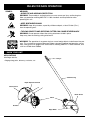
1
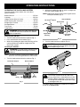
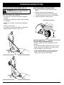
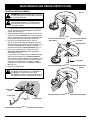
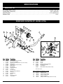
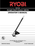
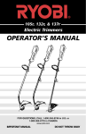
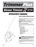
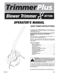
LE720r
Edger Add-On
OPERATOR’S MANUAL
FOR QUESTIONS, CALL 1-800-345-8746 in U.S. or
1-800-265-6778 in CANADA
www.ryobi.com
IMPORTANT MANUAL
DO NOT THROW AWAY
INTRODUCTION
TABLE OF CONTENTS
THANK YOU
Thank you for buying this quality product. This modern
outdoor power tool will provide many hours of useful
service. You will find it to be a great labor-saving device.
This operator’s manual provides you with easy-to-understand operating instructions. Read the whole manual
and follow all the instructions to keep your new outdoor
power tool in top operating condition. The parts list at
the end of this manual contains all the information that
you need to order parts.
PRODUCT REFERENCES, ILLUSTRATIONS AND
SPECIFICATIONS
All information, illustrations and specifications
in this manual are based on the latest product
information available at the time of printing. We reserve
the right to make changes at any time without notice.
Copyright© 1999 Ryobi Outdoor Products, Inc.
All Rights Reserved.
Click-Link® is a registered trademark of Ryobi Outdoor
Products.
SERVICE INFORMATION
Service on this unit both within and after the warranty
period should be performed only by
an authorized and approved service dealer.
Dial:
1-800-345-8746 in the United States or
1-800-265-6778 in Canada
to obtain the listing of the authorized service dealer
nearest you.
DO NOT RETURN THE UNIT TO THE RETAILER.
I.
Rules for Safe Operation . . . . . . . . . . . . . . . . . . . . . 3-6
A. Important Safety Information . . . . . . . . . . . . . . . 3-4
B. Safety and International Symbols . . . . . . . . . . . .4-5
C. Know Your Unit . . . . . . . . . . . . . . . . . . . . . . . . . . . . 5
II.
Operating Instructions . . . . . . . . . . . . . . . . . . . . . . . 6-7
A. Operating Click-Link System . . . . . . . . . . . . . . . . . 6
B. Holding the Unit with Edger Add-On . . . . . . . . . . . 7
C. Adjusting Edger Cutting Depth . . . . . . . . . . . . . . . . 7
D. Tips for Best Edging Results . . . . . . . . . . . . . . . . . 7
III. Maintenance and Repair Instructions . . . . . . . . . . . . . 8
A. Edger Blade Replacement . . . . . . . . . . . . . . . . . . . 8
IV. Specifications . . . . . . . . . . . . . . . . . . . . . . . . . . . . . . . 9
V. Parts List . . . . . . . . . . . . . . . . . . . . . . . . . . . . . . . . . . . 9
VI. Warranty . . . . . . . . . . . . . . . . . . . . . . . . . . . . . . . . . . 10
CONTENTS OF CARTON
This unit should consist of the following:
• LE720r Edger Add-On
• Locking Rod
• Hanger
• Operator's Manual with Parts List
• Product Registration Card
NOTE: PROOF OF PURCHASE WILL BE REQUIRED
FOR WARRANTY SERVICE.
Make sure this manual is carefully read and understood
before starting or operating this equipment.
THIS PRODUCT IS COVERED BY ONE OR
MORE US PATENTS.
OTHER PATENTS PENDING.
WARNING!
Read the Operator’s Manual(s) and follow all warnings and safety instructions. Failure to do so can
result in serious injury to the operator and/or bystanders.
FOR QUESTIONS, CALL 1-800-345-8746 IN U.S. OR 1-800-265-6778 in CANADA
2
RULES FOR SAFE OPERATION
The purpose of safety symbols is to attract your
attention to possible dangers. The safety symbols,
and their explanations, deserve your careful attention
and understanding. The safety warnings do not by
themselves eliminate any danger. The instructions or
warnings they give are not substitutes for proper
accident prevention measures.
SYMBOL
MEANING
SAFETY ALERT SYMBOL: Indicates
danger, warning, or caution. Attention is
required in order to avoid serious personal
injury. May be used in conjunction with
other symbols or pictographs.
NOTE: Advises you of information or instructions vital to
the operation or maintenance of the equipment.
DANGER: Failure to obey a safety warning
will result in serious injury to yourself or to
others. Always follow the safety precautions
to reduce the risk of fire, electric shock, and
personal injury.
WARNING: Failure to obey a safety warning
can result in injury to yourself and others.
Always follow the safety precautions to
reduce the risk of fire, electric shock, and
personal injury.
CAUTION: Failure to obey a safety warning
may result in property damage or personal
injury to yourself or to others. Always follow
the safety precautions to reduce the risk of
fire, electric shock, and personal injury.
• IMPORTANT SAFETY INFORMATION •
READ ALL INSTRUCTIONS
BEFORE OPERATING
• Read the instructions carefully. Be familiar with the
controls and proper use of the unit. Carefully read this
manual and the operator’s manual of the unit that will
power this add-on.
• Do not operate this unit when tired, ill, or under the
influence of alcohol, drugs, or medication.
• Children and teens under the age of 15 must not use
the unit, except for teens guided by an adult.
• Inspect the unit before use. Ensure the blade is
installed correctly and secure.
• Clear the area to be edged before each use. Remove
all objects such as rocks, broken glass, nails, wire, or
string which can be thrown or become entangled in
the edging attachment.
SAFETY WARNINGS FOR GAS TRIMMERS AND
LAWN EDGERS
WARNING: Gasoline is highly flammable, and its vapors
can explode if ignited. Take the following precautions:
• Store fuel only in containers specifically designed and
approved for the storage of such materials.
• Always stop the engine and allow it to cool before
filling the fuel tank. Never remove the cap of the fuel
tank, or add fuel, when the engine is hot. Never
operate the unit without the fuel cap securely in place.
Loosen the fuel tank cap slowly to relieve any pressure
in the tank.
• Mix and add fuel in a clean, well-ventilated area
outdoors where there are no sparks or flames. Slowly
remove the fuel cap only after stopping engine. Do not
smoke while fueling or mixing fuel. Wipe up any spilled
fuel from the unit immediately.
• Avoid creating a source of ignition for spilled fuel. Do
not start the engine until fuel vapors dissipate.
• Move the unit at least 30 feet (9.1 m) from the fueling
source and site before starting the engine. Do not
smoke, keep sparks and open flames from the area
while adding fuel or operating the unit.
• Never start or run the unit inside a closed room or
building. Breathing exhaust fumes can kill. Operate
this unit only in a well ventilated area outdoors.
SAFETY WARNINGS FOR ELECTRIC TRIMMERS
AND LAWN EDGERS
• WARNING: To reduce the risk of electrical shock, use
only extension cords approved for outdoor use, such
as an extension cord of cord type SW-A, SOW-A,
STW-A, STOW-A, SJW-A, SJOW-A, SJTW-W or
SJTOW-A. Extension cords are available from your
local retailer. Use only round-jacketed extension cords
approved for outdoor use.
• CORD SETS: Make sure your cord set is in good
condition. When using a cord set, be sure to use a
cord that is heavy enough to carry the current that
your unit will draw.An undersized cord set will cause a
drop in line voltage resulting in loss of power and overheating. See the operator’s manual for the unit that will
power this add-on for the recommended cord size.
• Inspect all extension cords and the unit power
connection periodically. Look closely for deterioration,
cuts or cracks in the insulation. Also inspect the
connections for damage. Replace the cords if any
defects or damage appear.
• Avoid dangerous environments. Never operate your
unit in damp or wet conditions. Moisture is a shock
hazard.
• Do not use the unit in the rain.
• Do not handle the plug or unit with wet hands or
standing on any wet surfaces.
• Do not leave the unit plugged in when not in use,
changing attachments or add-ons, or while
being serviced.
3
RULES FOR SAFE OPERATION
WHILE OPERATING
• Wear safety glasses or goggles that are marked as
meeting ANSI Z87.1-1989 standards, and ear/hearing
protection when operating this unit. Wear a face or
dust mask if the operation is dusty. Long sleeve shirts
are recommended.
• Wear heavy, long pants, boots and gloves. Do not
wear loose clothing, jewelry, short pants, sandals or
go barefoot. Secure hair above shoulder level.
• The edger shield must always be in place while
operating the unit.
• Use the unit only in daylight or good artificial light.
• Use the right tool. Only use this tool for the purpose
intended.
• Do not overreach. Always keep proper footing and
balance.
• Always hold the unit with both hands when operating.
Keep a firm grip on both the front and rear handle or
grips.
• A coasting blade can cause injury while it continues to
spin after the unit is stopped. Maintain proper control
of the unit until the blade has completely stopped
rotating.
• Keep hands, face, and feet at a distance from all
moving parts. Do not attempt to touch or stop the
blade when it is rotating.
• Do not operate the unit faster than the speed
needed to edge. Do not run the unit at high speed
when not edging.
• Always stop the unit when work is delayed or when
walking from one cutting location to another.
• If you strike or become entangled with a foreign
object, stop the engine immediately and check for
damage. Have any damage repaired before attempting
further operations. Do not operate unit with a bent,
cracked or dull blade. Discard blades that are bent,
warped, cracked or broken.
• Stop the unit IMMEDIATELY if you feel excessive
vibration. Vibration is a sign of trouble. Inspect
thoroughly for loose nuts, bolts or damage before
continuing. Repair or replace affected parts as
necessary.
• Stop and switch the unit to off for maintenance,
repair, or for changing add-ons or other attachments.
• Use only genuine Ryobi replacement parts when
servicing this unit. These parts are available from
your authorized service dealer. Do not use parts,
accessories or attachments not authorized by Ryobi
for this unit. Doing so could lead to serious injury to
the user, or damage to the unit, and void your
warranty.
OTHER SAFETY WARNINGS
• Allow the unit to cool before storing or transporting.
Be sure to secure the unit while transporting.
• Store the unit in a locked up and dry or high and dry
place to prevent unauthorized use or damage, out of
the reach of children.
• Never douse or squirt the unit with water or any other
liquid. Keep handles dry, clean and free from debris.
Clean after each use, see Cleaning and Storage
instructions.
• Keep these instructions. Refer to them often and use
them to instruct other users. If you loan someone this
unit, also loan them these instructions.
SAVE THESE INSTRUCTIONS
SAFETY AND INTERNATIONAL SYMBOLS
This operator's manual describes safety and international symbols and pictographs that may appear on this product.
Read the operator's manual for complete safety, assembly, operating and maintenance and repair information.
SYMBOL
MEANING
• SAFETY ALERT SYMBOL
Indicates danger, warning, or caution. May be used in conjunction with other
symbols or pictographs.
• WARNING - READ OPERATOR'S MANUAL
Read the Operator’s Manual(s) and follow all warnings and safety instructions.
Failure to do so can result in serious injury to the operator and/or bystanders.
• FOR SERVICE INFORMATION, CALL:
USA: 1-800-345-8746
CANADA: 1-800-265-6778
4
RULES FOR SAFE OPERATION
SYMBOL
MEANING
• WEAR EYE AND HEARING PROTECTION
WARNING: Thrown objects and loud noise can cause severe eye injury and hearing loss.
Wear eye protection meeting ANSI Z87.1-1989 standards and ear protection when
operating this unit.
• KEEP BYSTANDERS AWAY
WARNING: Keep all bystanders, especially children and pets, at least 50 feet (15 m.)
from the operating area.
• THROWN OBJECTS AND ROTATING CUTTER CAN CAUSE SEVERE INJURY
WARNING: Do not operate without the cutting attachment shield in place.
Keep away from the rotating cutting attachment.
WARNING: The operation of any power tool can cause foreign objects to be thrown into your
eyes. This can lead to severe eye damage. Before commencing power tool operation, always
wear safety glasses or goggles that are marked as meeting ANSI Z87.1-1989 standards, and
a full face shield when needed.
KNOW YOUR UNIT
APPLICATIONS
With Edger Add-On;
• Edging along paths, driveways, rockeries, etc.
Hanger
Shaft Housing
Depth Adjustment Knob
Blade Shield
Blade Shield
Wheel
Gearbox
Edger Blade
5
OPERATING INSTRUCTIONS
OPERATING THE CLICK-LINK® SYSTEM
The Click-Link® system enables the use of these
optional add-ons.
Blower/Vacuum . . . . . . . . . . . . . . . . . . . . . . . . . . BV720r
Cultivator . . . . . . . . . . . . . . . . . . . . . . . . . . . . . . GC720r
Hedge Trimmer (Gas units only) . . . . . . . . . . . . . HS720r
Snow Thrower (Gas units only) . . . . . . . . . . . . . . ST720r
Straight Shaft Trimmer . . . . . . . . . . . . . . . . . . . . SS725r
Sweeper/Blower . . . . . . . . . . . . . . . . . . . . . . . . . SB720r
Tree Pruner . . . . . . . . . . . . . . . . . . . . . . . . . . . . . TP720r
Turbo Blower . . . . . . . . . . . . . . . . . . . . . . . . . . . . TB720r
WARNING: Read and understand operator’s
manual for unit to be used with this add-on
prior to operation.
Removing the Add-Ons:
1. Turn the knob counterclockwise to loosen (Fig. 1).
2. Press and hold the release button (Fig. 1).
3. While firmly holding the upper shaft housing, pull the
cutting attachment or add-on straight out of the
Click-Link® coupler.
Installing the Add-Ons:
2. While firmly holding the add-on, push it straight into
the Click-Link® coupler (Fig. 2).
NOTE: Aligning the release button with the guide recess
will help installation (Fig. 2).
Release Button
Click-Link® Coupler
Primary Hole
Upper Shaft
Housing
Lower Shaft
Housing
Fig. 2
3. Turn the knob clockwise to tighten (Fig. 3).
CAUTION: Lock the release button in the
primary hole and securely tighten the knob
before operating this unit.
WARNING: To avoid serious personal injury,
shut unit off before removing or installing
add-ons.
NOTE: To make installing or removing the add-on easier,
place the unit on the ground or on a work bench.
1. Turn the knob counterclockwise to loosen (Fig. 1).
Click-Link® Coupler
Release Button
Knob
Fig. 3
Guide
Recess
Knob
Fig. 1
CAUTION: The add-ons with the
Click-Link® system are to be used in the
primary hole unless stated otherwise in the
specific add-ons operator’s manual. Using
the wrong hole could lead to personal injury,
or damage to the unit.
The edger add-on should be installed with the release
button in the primary hole.
6
OPERATING INSTRUCTIONS
HOLDING THE UNIT WITH EDGER ADD-ON
WARNING: Always wear eye, hearing, foot
and body protection to reduce the risk of
injury when operating this unit.
Before operating the unit, stand in the operating position
(Figs. 4 & 5). Check for the following:
• The operator is wearing eye protection and proper
clothing.
• The right arm is slightly bent, and the hand is holding
the shaft grip.
ADJUSTING EDGER CUTTING DEPTH
1. Loosen the adjustment knob above the wheel
(Fig 6).
2. Slide the wheel to the desired position.
• Raising the wheel increases the cutting depth.
• Lowering the wheel decreases the cutting depth.
3. Tighten the adjustment knob securely.
Depth Adjustment Knob
• The left arm is straight, and the hand is holding the
handle.
• The unit is at waist level.
• The edger wheel adjusted for proper cut depth and
edger positioned as shown in Figs. 4 or 5.
Raising
Lowering
Fig. 6
TIPS FOR BEST EDGING RESULTS
• Keep the cutting attachment perpendicular to the
ground.
• Do not force the edger. Edge the first time at a lesser
depth, then do the area again with a deeper setting.
• Walk the edger at a slow, even pace
• Check the blade condition, as it wears it becomes
smaller, reducing the cutting depth performance.
Replace with a new blade as required.
Fig. 4
Fig. 5
7
MAINTENANCE AND REPAIR INSTRUCTIONS
EDGER BLADE REPLACEMENT
Loosen
WARNING: To avoid serious personal injury,
always wear gloves while handling, removing
or installing the blade.
WARNING: The gear housing gets hot
after long periods of use. To avoid serious
personal injury, do not touch the housing
until it has cooled.
1. Line up the hole in output shaft with the locking rod
slot. Insert the locking rod through the slot into the
output shaft hole (Fig. 7).
2. While holding the locking rod, loosen the nut on the
blade by turning it clockwise with a 5/8 inch wrench
(Fig. 8). Remove the nut, retaining washer and blade.
Keep the nut and blade retainer for installation.
3. Install the new blade, blade retainer, and nut
(Fig. 9). Insert the locking rod through the slot into
the output shaft hole. Make sure that the blade stays
flat and centered against the output shaft while
tightening the lock nut counterclockwise (Fig. 10).
4. If you have a torque wrench, tighten the nut to
325-335 in.•lbs (37-38 N•m), while holding the
locking rod in the slot.
If you do not have a torque wrench, hold the locking
rod in the slot. Rotate the nut counterclockwise
with a 5/8 inch closed-ended or socket wrench, until
the nut presses against the washer and the blade is
snug. Make sure the blade assembly is installed
correctly, then rotate the nut an additional 1/4-1/2
turn (Fig. 10).
5. Remove the locking rod.
Fig. 8
Lock Nut
Edger Blade
Blade Retainer
Locking Rod
Fig. 9
Tighten
WARNING: Verify the blade is flat against
the output shaft after the nut is tightened. If
the blade is off-center, the unit will be
damaged by vibration, and the blade may fly
off, which can cause serious personal injury.
Output Shaft
Hole
Fig. 10
Locking Rod
Locking Rod
Slot
Fig. 7
8
Output Shaft
SPECIFICATIONS
EDGER ADD-ON
Unit Weight (Add-On only) . . . . . . . . . . . . . . . . . . . . . . . . . . . . . . . . . . . . . . . . . . . . . . . . . . . . . . . 5.25 lbs. (2.36 kg.)
Cutting Depth (maximum) . . . . . . . . . . . . . . . . . . . . . . . . . . . . . . . . . . . . . . . . . . . . . . . . . . . . . . . . . . 2.5 in. (63.5 mm)
Wheel Diameter . . . . . . . . . . . . . . . . . . . . . . . . . . . . . . . . . . . . . . . . . . . . . . . . . . . . . . . . . . . . . . . 3.75 in (95.25 mm)
Gearbox Ratio . . . . . . . . . . . . . . . . . . . . . . . . . . . . . . . . . . . . . . . . . . . . . . . . . . . . . . . . . . . . . . . . . . . . . . . . . . 1.23:1
EDGER ADD-ON PARTS LIST - MODEL LE720r
18
17
16
20
19
10
9
11
8
21
1
12
13
20
14
4
15
2
12
5
27
26
4
28
22
6
22
7
3
6
24
23
29
25
5
Item
Part No.
Description
Item
Part No.
Description
1
2
3
4
5
6
7
8
9
10
11
12
13
14
15
16
17
612605
180915
181570
147488
182196
182200
181245
613223
147490
147491
182213
181591
181592
181593
181242
182214
182215
Hanger
Drive Shaft Housing Assembly
Drive Shaft Assembly
Gearbox Assembly (includes 5, 6, 10, 19 & 20)
Blade Driver
Shield Mount Screw Assembly
Blade Shield
Edger Blade
Retaining Washer
Lock Nut
Shoulder Bolt
Wheel Mounting Hardware
Deflector
Guide Bracket
Wheel
Adjustment Knob
Lock Washer
18
19
20
21
22
23
*
*
182216
182237
182236
181858
182195
145569
613226
180014
Washer
Locknut
Washer
Screw
Gearbox Mounting Hardware
Anti-Rotation Screw
Locking Rod
Blade Retainer Kit (includes 9 & 10)
*
Items Not Shown
2 Piece Gearbox Assembly Parts – Item 4
24
182191
Left Housing
25
182192
Right Housing
26
182194
Pinion Gear Assembly
27
182199
Output Shaft Bushing
28
182198
Output Shaft Gear
29
182197
Output Shaft Assembly (includes 27 & 28)
9
LIMITED TWO-YEAR WARRANTY
RYOBI OUTDOOR PRODUCTS warrants each new
RYOBI Product for two (2) years according to the
following terms.
This warranty extends to the original retail purchaser
only and commences on the date of original retail
purchase.
Any part of the RYOBI Product manufactured or
supplied by RYOBI and found in the reasonable
judgement of RYOBI to be defective in material or
workmanship will be repaired or replaced by an
authorized RYOBI service dealer without charge for
parts and labor.
The RYOBI Product including any defective part must
be returned to an authorized service dealer within the
warranty period. The expense of delivering the RYOBI
Product to the dealer for warranty work and the
expense of returning it back to the owner after repair
or replacement will be paid for by the owner. RYOBI’s
responsibility in respect to claims is limited to making
the required repairs or replacements and no claim of
breach of warranty shall be cause for cancellation or
rescission of the contract of sale of any RYOBI
Product. Proof of purchase will be required by the
dealer to substantiate any warranty claim. All warranty
work must be performed by an authorized RYOBI
service dealer.
This warranty is limited to ninety (90) days from the
date of original retail purchase for any RYOBI Product
that is used for rental or commercial purposes, or any
other income-producing purpose.
This warranty does not cover any RYOBI Product that
has been subject to misuse, neglect, negligence, or
accident, or that has been operated in any way
contrary to the operating instructions as specified in
the RYOBI Operator’s Manual. This warranty does not
apply to any damage to the RYOBI Product that is the
result of improper maintenance or to any RYOBI
Product that has been altered or modified so as to
adversely affect the product's operation, performance
or durability or that has been altered or modified so as
to change its intended use. The warranty does not
extend to repairs made necessary by normal wear or
by the use of parts or accessories which are either
incompatible with the RYOBI Product or adversely
affect its operation, performance or durability.
RYOBI reserves the right to change or improve the
design of any RYOBI Product without assuming
any obligation to modify any product previously
manufactured.
ALL IMPLIED WARRANTIES ARE LIMITED IN
DURATION TO THE TWO (2) YEAR WARRANTY
PERIOD OR NINETY (90) DAYS FOR PRODUCTS
USED FOR ANY COMMERCIAL PURPOSE.
ACCORDINGLY, ANY SUCH IMPLIED WARRANTIES
INCLUDING MERCHANTABILITY, FITNESS FOR A
PARTICULAR PURPOSE, OR OTHERWISE, ARE
DISCLAIMED IN THEIR ENTIRETY AFTER THE
EXPIRATION OF THE APPROPRIATE TWO-YEAR
OR NINETY DAY WARRANTY PERIOD. RYOBI’S
OBLIGATION UNDER THIS WARRANTY, IS STRICTLY
AND EXCLUSIVELY LIMITED TO THE REPAIR OR
REPLACEMENT OF DEFECTIVE PARTS, AND ROP
DOES NOT ASSUME OR AUTHORIZE ANYONE TO
ASSUME FOR THEM ANY OTHER OBLIGATION.
SOME STATES DO NOT ALLOW LIMITATIONS ON
HOW LONG AN IMPLIED WARRANTY LASTS, SO
THE ABOVE LIMITATION MAY NOT APPLY TO YOU.
RYOBI ASSUMES NO RESPONSIBILITY FOR
INCIDENTAL, CONSEQUENTIAL OR OTHER
DAMAGES INCLUDING, BUT NOT LIMITED TO
EXPENSE OF RETURNING THE RYOBI PRODUCT
TO AN AUTHORIZED SERVICE DEALER AND
EXPENSE OF DELIVERING IT BACK TO THE
OWNER, MECHANIC’S TRAVEL TIME, TELEPHONE
OR TELEGRAM CHARGES, RENTAL OF A LIKE
PRODUCT DURING THE TIME WARRANTY SERVICE
IS BEING PERFORMED, TRAVEL, LOSS OR DAMAGE
TO PERSONAL PROPERTY, LOSS OF REVENUE,
LOSS OF USE OF THE PRODUCT, LOSS OF TIME,
OR INCONVENIENCE. SOME STATES DO NOT
ALLOW THE EXCLUSION OR LIMITATION OF
INCIDENTAL OR CONSEQUENTIAL DAMAGES, SO
THE ABOVE LIMITATION OR EXCLUSION MAY NOT
APPLY TO YOU.
This warranty gives you specific legal rights, and you
may also have other rights which vary from state to
state.
This warranty applies to all RYOBI Products
manufactured by RYOBI and sold in the United States
and Canada.
To locate your nearest service dealer dial
1-800-345-8746 in the United States or
1-800-265-6778 in Canada.
RYOBI OUTDOOR PRODUCTS
550 N. 54th Street
Chandler, AZ 85226 U.S.A.
RYOBI CANADA INC.
275 Industrial Rd
Cambridge, Ontario N1R 6K2 CANADA
SAVE THESE INSTRUCTIONS FOR FUTURE REFERENCE.
FOR QUESTIONS CALL 1-800-345-8746 IN U.S.
OR 1-800-265-6778 IN CANADA
OPERATOR’S MANUAL PART NO. 182235
PRINTED IN U.S.A.
REV. A (7957)
1/99