1
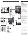
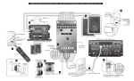
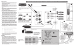
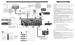
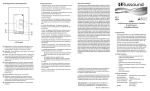
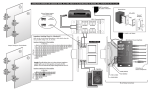
A-H1 OVERVIEW
INSTRUCTIONS FOR CONNECTING AND USING RUSSOUND® MODEL A-H1. REFER TO THE DIAGRAMS INSIDE.
Model A-H1
A-H1 CONNECTIONS
SOURCE
Note: When making all connections, be sure that the power supply
is not connected.
Although the A-H1 has only 1 audio input, it can be connected to
multiple audio sources via the Tape 2 or Zone 2 output of a stereo or
home theater receiver. Connecting to a receiver gives the A-H1 access
to any audio source connected to that receiver. Alternately, a single
audio source can be connected directly to the A-H1.
The A-H1 must be connected to the Link In connector on the
A-H4P or other A-BUS ready product or hub. Connect the hub output to an RJ-45 wall plate. Wire the RJ-45 for the T568A standard
using CAT-5 conductor wire. When using pre-made CAT-5 RJ-45
patch cables, be sure they are straight through and do not swap
conductor pairs.
Run the CAT-5 from the rear of the wall plate to the structured
wiring panel and then to the A-H4P. Use the following color code
markings to connect the CAT-5 to the Input 110 punchdown connector on the A-H4P. (Use a punchdown tool with a 110 blade to
insert conductors).
Brown
Brown/White
Green
Green/White
Orange
Orange/White
Blue
Blue/White
V+
VL+
LR+
RIR
Status
Run the CAT-5 from each of the A-BUS keypad modules to the
structured wiring panel. Follow the above color code and punch
down the CAT-5 for each keypad output 110 punchdown
connector.
After all of the punchdown connections are made, route the cables
in the box so they avoid power lines and are not grouped with
other cables in the panel.
IR EMITTERS
Connect an IR emitter such as the 845.1 to each of the 4 IR connectors on the A-H1 (you need use only one IR emitter if you’ve
connected a single source directly to the A-H1). The IR signal that
is received through a zone’s Amplified Keypad is routed to the
A-H1’s Common IR outputs. This allows remote operation of
sources such as CD, DVD, or DSS from each zone.
INDICATORS
POWER - The Power LED will be illuminated when the 24VDC
power supply attached to the A-H4P is on.
STATUS INDICATOR - The Status Indicator will be illuminated when
12VDC is present at the Status Input connector, indicating the
source equipment is on.
IR - The red LED will flash when IR signals are received by the
A-BUS keypads. This is used to confirm IR reception from the
A-H4P.
STATUS SWITCH
The status feature provides two functions:
- Visually confirms when the source component is on.
- When the source component is turned off, all Amplified Modules
will also turn off.
The status feature requires that the source component has a
switched AC outlet.
To enable the status feature:
- Move the status jumper on all Amplified Modules to the
“Enabled” position.
- Move the status switch on the Hub to the “STATUS” position.
- Using a Russound Model 846C 120V/12VDC or comparable
adapter, connect the coaxial plug end to the STATUS input on
the Hub, and plug the adapter into a switched AC outlet on the
source component.
When the source is on and supplying status voltage to the Hub, the
Amplified Module’s LED indicator will illuminate green. When the
source is turned off, all Amplified Modules that are on will also
turn off (the A-VC will mute).
IMPORTANT: When the status feature is enabled, it must be used
(i.e., supplied with power) in order to ensure proper operation with
accessories such as the A-LC2 Local Source Input Module.
Audio Interface Hub
for A-BUS® System
Instruction Manual
A-BUS® SYSTEM OVERVIEW
The product you have just purchased is an integral part of the Russound®
A-BUS Multi-Room Audio System. It is a component which, when combined
with other essential components and your source equipment (receiver, CD player, etc.), creates a versatile whole-house audio system that will fill your rooms
with high-quality sound for years to come.
A-BUS technology is a new, innovative method of providing high quality audio
to remote locations with a single 8-conductor cable such as CAT-5. A-BUS
technology provides many advantages over other methods of audio distribution, including: simple, single CAT-5 wiring scheme; infrared control of system
components; infrared control of the optional A-KP2 amplified keypad module;
and system power status.
Every A-BUS System is comprised of components from each of the following
three areas.
1. A-BUS Amplified Modules: The Module contains both the amplifier for the
room’s speakers as well as the control for those speakers. One Module
should be used for each room you choose to control. The Russound A-KP2
Amplified Keypad (with built-in IR receiver) and A-VC Amplified Volume
Control are examples of A-BUS Amplified Modules.
2. A-BUS Hubs: All components of the A-BUS system must be wired centrally
to a Hub located near your source equipment. The Hub provides the connection for source equipment, volume controls, infrared emitters and power
supply. The A-H484, A-H4, A-H4P, and A-H2 are examples of A-BUS Hubs.
3. Power Supply: The power supply plugs into the Hub. The Russound A-PS
24VDC/2.5A unit is an example.
A-BUS® is a registered trademark of LeisureTech Electronics Pty Ltd Australia
Mount the A-H1 using screws or hook and loop fastener. Securely
mount the A-H1 within 6 feet of source equipment.
28-1147
A-H1 KEY FEATURES
1)
2)
3)
4)
5)
1 source audio input
4 common IR outputs, with confirmation LED
Status power input with LED indicator
Main Power LED indicator
Compact size for mounting near audio equipment
A-H1 SPECIFICATIONS
Status Power:
Input:
Output:
Emitter Connections:
Dimensions:
Weight:
12VDC/100mA 2.5mm plug
600 ohm line-level audio (RCA)
A-BUS ready RJ-45 T568A Standard
1/8" Male, Tip (+), sleeve (–)
6.5"W x 2"H x 1.55"D (165 x 51 x 39mm)
9.5 oz. (270g)
LIMITED WARRANTY
The Russound A-H1 is fully guaranteed for two (2) years from the date of purchase against all defects in materials and workmanship. For this warranty to
apply, the unit must be installed and used according to its written instructions.
During this period, Russound will replace any defective parts and correct any
defect in workmanship without charge for either parts or labor. Accidental damage and shipping damage are not considered defects under the terms of this
warranty. Russound assumes no responsibility for defects resulting from abuse or
servicing performed by an agency or person not specifically authorized in writing by Russound. If service is necessary, it must be performed by Russound.
Damage to or destruction of components due to excessive power voids the warranty. In these cases, the repair will be made at the owner’s expense. To return
for repairs, the unit must be shipped to Russound at the owner’s expense, along
with a note explaining the nature of the service required. Be sure to pack in a
corrugated container with at least 3 inches of resilient material to protect the
unit from damage in transit.
Before returning a unit for repair, call Russound at (603) 659-5170 for a Return
Authorization number. Write the RA number on the shipping label and ship to:
Russound, ATTN: Service, 5 Forbes Road, Newmarket NH 03857
5 Forbes Rd. Newmarket, NH 03857, USA
☎ 603.659.5170 • Fax 603.659.5388
e-mail: [email protected]
MOUNTING
The A-H1 is an A-BUS Audio Interface Hub that provides an interface for audio, status, voltage and infrared between the source
equipment and the A-H4P A-BUS hub (cannot be used with the AH4D). The A-H1 can interface a stereo receiver to an A-BUS system
using the A-H4P.
Come visit us at:
Russound sells product only through authorized Dealers and Distributors to
ensure that customers obtain proper support and service. Any Russound product
purchased from an unauthorized dealer or other source, including retailers, mail
order sellers and online sellers will not be honored or serviced under existing
Russound warranty policy. Any sale of products by an unauthorized source or
other manner not authorized by Russound shall void the warranty on the applicable product.
SAFETY INSTRUCTIONS
CONNECTION DIAGRAM FOR RUSSOUND® MODEL A-H1. REFER TO THE INSTRUCTIONS ON BACK. DIAGRAMS ARE NOT TO SCALE.
Safety Instructions:
1. Read Instructions - All the safety and operating instructions should be read
before the appliance is operated.
2. Retain Instructions - The safety and operating instructions should be retained
for future reference.
110 punchdown connectors for Amplified Keypads
RJ-45 Connection Details
A-H4P
CAT-5
(behind wall)
87
65
43
V+
VL+
LR+
RIR
ST
B
BW
G
GW
O
OW
BL
BLW
V+
VL+
LR+
RIR
ST
1
INPUT
21
RJ45 Wall Plate (optional)
located near Hub
When wiring use T568A RJ45 wire configuration
IR
A-H4P
RJ45 CAT-5
patch cable
Source Component
Alternate method: Connect 1 source directly
A-H1
OUT
V+
VL+
LR+
RIR
ST
2
3
6. Wall or Ceiling Mounting - The appliance should be mounted to a wall or ceiling only as recommended by the manufacturer.
POWER
4
POWER
+24V
2,5A
KEYPAD OUTPUTS
SYSTEM ON
LINK
IN
DESIGNED IN USA MADE IN KOREA
Brown
Brown/White
Green
Green/White
Orange
Orange/White
Blue
Blue/White
V+
VL+
LR+
RIR
Status
CAT-5 Wiring Scheme for
110 punchdown connector
Audio Receiver
BYPASS
Pos (+)
ON
OFF
ROOM
A-KP2
A-LRC1
CD
TAPE
8. Heat - The appliance should be situated away from heat sources such as
radiators, heat registers, stoves, or other appliances (including amplifiers)
that produce heat.
9. Power Sources - The appliance should be connected to a power supply only
of the type described in the operating instructions or as marked on the appliance.
10.Grounding or Polarization - Precaution should be taken so that the grounding
or polarization means of an appliance is not defeated.
11.Power Cord Protection - Power supply cords should be routed so that they
are not likely to be walked on or pinched by items placed upon or against
them, paying particular attention to cords at plugs, receptacles, and the point
where they exit from the appliance.
13.Damage Requiring Service - The appliance should be serviced by qualified
service personnel when:
Standard method: Connect multiple sources
via Tape 2 or Zone 2 output of Receiver
A-KP RC
7. Ventilation - The appliance should be situated so that its location or position
does not interfere with its proper ventilation. For example, the appliance
should not be situated on a bed, sofa, rug, or similar surface that may block
the ventilation openings, or placed in a built-in installation, such as a bookcase or cabinet that may impede the flow of air through the ventilation openings.
12.Object and Liquid Entry - Care should be taken so that objects do not fall and
liquids are not spilled into the enclosure through the openings.
STATUS
846C
A-VC
4. Follow Instructions - All operating and user instructions should be followed.
5. Water and Moisture - The appliance should not be used near water; for
example, near a bathtub, washbowl, kitchen sink, laundry tub, in a wet basement, or near a swimming pool.
NEWMARKET, NH U.S.A.
4-ZONE, 1-SOURCE
AUDIO STRUCTURED WIRING HUB
3. Heed Warnings - All warnings on the appliance in the operating instructions
should be adhered to.
Neg (–)
To switched AC outlet
on Audio Receiver
Audio Receiver
A.
The power supply cord or the plug has been damaged; or
B.
Objects have fallen, liquid has been spilled into the appliance; or
C.
The appliance has been exposed to rain; or
D.
The appliance does not appear to operate normally; or
E.
The appliance has been dropped or the enclosure is damaged.
14.Servicing - The user should not attempt to service the appliance beyond that
described in the operating instructions. All other servicing should be referred
to qualified service personnel.
VOLUME
A-KP RC
DSS
TUNER
Emitter attaches to each source
component’s IR window
Precautions:
1. Power – WARNING: BEFORE TURNING ON THE POWER FOR THE FIRST
TIME, READ THE FOLLOWING SECTION CAREFULLY.
All models are designed for use with either AC120V, 60Hz or AC240, 50Hz
voltages. The unit will autoswitch to either of these voltages.
2. Do Not Touch The A-H1 With Wet Hands – Do not handle the AH-1 or power
cord when your hands are wet or damp. If water or any other liquid enters
the A-H1 cabinet, take the A-H1 to a qualified service person for inspection.
3. Care – From time to time you should wipe off the front and side panels of the
cabinet with a soft cloth. Do not use rough material, thinners, alcohol or
other chemical solvents or cloths since this may damage the finish or
remove the panel lettering.