1
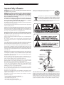
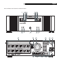
Owner’s Manual
RLC-1080
Power Conditioner
To register your purchase now, go to www.rotel.com
RLC-1080 Power Conditioner
2
Important Safety Information
WARNING: There are no user serviceable parts inside. Refer all servicing
to qualified service personnel.
WARNING: To reduce the risk of fire or electric shock, be sure that the
apparatus shall not be exposed to dripping or splashing and that no
objects filled with liquids, such as vases, shall be placed on the apparatus.
Do not use this product in an environment where the relative humidity
may exceed 95% (non-condensing).
Do not allow foreign objects to get into the enclosure. If the unit is exposed
to moisture, or a foreign object gets into the enclosure, immediately
disconnect the power cord from the wall. Take the unit to a qualified
service person for inspection and necessary repairs.
Place the unit on a fixed, level surface strong enough to support its weight.
Do not place it on a moveable cart that could tip over.
Rotel products are designed to comply with international directives
on the Restriction of Hazardous Substances (RoHS) in electrical
and electronic equipment and the disposal of Waste Electrical and
Electronic Equipment (WEEE). The crossed wheelie bin symbol indicates
compliance and that the products must be appropriately recycled or
processed in accordance with these directives.
Read all the instructions before connecting or operating the component. Keep this manual
so you can refer to these safety instructions.
Heed all warnings and safety information in these instructions and on the product itself.
Follow all operating instructions.
Unplug this device from the wall outlet before cleaning. Clean the enclosure only with a
dry cloth or a vacuum cleaner. Note: A product that is meant for uninterrupted service
and for some specific reason, such as the possibility of the loss of an authorization code
for a cable TV converter, is not intended to be unplugged by the user for cleaning or any
other purpose, may exclude the reference to unplugging this device.
You must allow 10 cm or 4 inches of unobstructed clearance around
the unit. Do not place the unit on a bed, sofa, rug, or similar surface that could block
the ventilation slots. If the component is placed in a bookcase or cabinet, there must be
ventilation of the cabinet to allow proper cooling.
Keep the component away from radiators, heat registers, stoves, or any other appliance
that produces heat.
The unit must be connected to a power supply only of the type and voltage specified
on the rear panel of the unit. Do not use a plug adapter which defeats the ground pin
of the AC plug.
Connect the component to the power outlet only with the supplied power supply cable
or an exact equivalent. Do not modify the supplied cable in any way. Do not attempt to
defeat grounding and/or polarization provisions. Do not use extension cords.
Do not route the power cord where it will be crushed, pinched, bent at severe angles,
exposed to heat, or damaged in any way. Pay particular attention to the power cord
at the plug and where it exits the back of the unit. After connecting other devices to this
device, do not push the rear of the device up against any surface (wall or shelving unit),
as this may create an undesired bend in the power cords which may break the wire
strands of the cord.
Although this device provides protection against electrical surges, when connecting an
outside antenna or cable system to devices connected to this device, ensure the antenna
or cable system is grounded so as to provide additional protection against voltage
surges and static charges in accordance with Section 810 of the National Electric Code,
ANSI/NFPA No.70 (see illustration).
This device provides a grounding lug at the rear panel for grounding the device to an
external Transient Voltage Surge Suppression (TVSS) device. Ensure this connection is
made in accordance with the instructions provided by the TVSS device.
This device employs Metal Oxide Varisters (MOVs), and other circuitry to protect against
lightning and other sources of voltage surges and sags. It is not necessary to turn this
device or the devices connected to this device, off during a lighting storm.
Do not locate outside antenna systems near overhead power lines, or other electric light
or power circuits, or where it may fall or otherwise come in contact with these power
sources. Do not allow the ladder being used, or the antenna itself to come into contact
with these power sources, as such contact may be fatal.
Do not overload the wall outlet where this device is being connected. Do not overload
this device. Ensure the total load to this device does not exceed that which is listed in the
Specifications section of this manual.
Inspect the line cords. telephone/data cords, or DSS/Cable TV coaxial cables connected
to this device to ensure they remain fully pushed in or attached, and that they are not
frayed or otherwise damaged.
Immediately stop using the component and have it inspected and/or serviced by a
qualified service agency if:
•
•
•
•
•
The power supply cord or plug has been damaged.
Objects have fallen or liquid has been spilled into the unit.
The unit has been exposed to rain.
The unit shows signs of improper operation
The unit has been dropped or damaged in any way
Federal Communications Commission (FCC) Compliance Information
This device complies with Part 68 and Part 15 of the FCC rules. Operation is subject to
the following two conditions: (1) This device must not cause harmful interference, and (2)
This device must accept any interference received, including interference that may cause
undesired operation. As required, the bottom of this equipment contains, among other
information, the Registration Number and Ringer Equivalence Number (REN) for this
equipment. If requested, this information must be provided to the telephone company.
English
3
Front and Rear Panel Controls and Connections
���
��
��
�
��
��
�
��
�
�
�
�
�
�
�
� �
� � �
RLC-1080 Power Conditioner
4
Contents
Important Safety Information ................. 2
Front and Rear Panel Controls and Connections 3
About Rotel ........................................... 4
Getting Started ...................................... 4
Features
5
Parts List
5
A Few Precautions ................................. 5
Power Capacity
5
Placement
5
Front Panel ............................................ 6
ON BATTERY Status Indicator 1
6
DELAYED 1 Status Indicator 2
6
DELAYED 2 Status Indicator 3
6
REGULATING Status Indicator 4
6
Vacuum Fluorescent Display 5
6
OVERLOAD Status Indicator 6
6
FILTERING Status Indicator 7
6
LINE OK Status Indicator 8
6
LOW BATTERY Status Indicator 9
6
STATUS Button 0
6
SETUP Button 6
On/Off Switch =
6
Up and Down Arrow Buttons qw
6
Removable Support Feet e
6
Rear Panel............................................. 7
AC-Power Outlets r
7
EXTERNAL BATTERY Connector t
7
Cooling Fan y
7
Surge Protected COAX/RF Connectors u
7
CIRCUIT BREAKER i
7
SYSTEM GROUND Screw o
7
DATA PORT Jack (USB) p
7
Surge Protected Telephone Jacks [
7
ETHERNET Surge Protected Jacks ]
7
DC TRIGGER Jacks \
7
Input Power Connector a
7
BUILDING WIRING FAULT Indicator s
7
About Rotel
Installation ............................................ 8
Placement
8
Rack Mounting
8
Connecting the Battery ........................... 8
System Test ........................................... 8
Status Screens ....................................... 9
Status Screens
9
INPUT VOLTAGE: XXXV OUTPUT VOLTAGE: XXXV 9
SYSTEM LOAD: <XXXWLOAD: <XXX%
9
EST. RUNTIME: XHRS FUEL: XXX%
9
Information Screens ............................... 9
SOURCE: XXXXXXX EST. RUNTIME: XHRS Screen 9
Firmware Version: XXXXXXX Screen
9
Model Number and Serial Number Screen
10
Internet Address Screen
10
INPUT FREQUENCY; OUTPUT FREQUENCY Screen 10
Connecting the Components .................. 10
Setting Up the RLC-1080 ..................... 10
AUDIBLE ALARM Setting
10
SENSITIVITY Setting
10
DISPLAY DIMMER Setting
11
LED DIMMER Setting
11
GO TO BATTERY IF > XXXV Setting
11
GO TO BATTERY IF < XXXV Setting
11
OUTLET DELAY1 and OUTLET DELAY2 Setting 11
LOWBATTWARNING: XMIN Setting
11
BATREPDATE: XX/XX/XX Setting
11
DO QUIK SELFTEST Screen
11
DO RUNTIME CAL Screen
12
DISPLY-BEEP TEST Screen
12
SCREEN SAVER: ON/OFF Screen
12
RESET TO DEFAULT: YES/NO Setting
12
Setting Default Screen
12
Troubleshooting.................................... 12
The RLC-1080 will not turn on
12
Connected equipment reboots or turns off
when the RLC-1080 switches to battery power. 13
Replace Battery LED is illuminated.
13
Limited Warranty ................................. 13
Specifications ....................................... 14
A family whose passionate interest in music led
them to manufacture high fidelity components
of uncompromising quality founded Rotel over
45 years ago. Over the years that passion has
remained undiminished and the goal of providing exceptional value for audiophiles and music
lovers regardless of their budget, is shared by
all Rotel employees.
Rotel’s reputation for excellence has been earned
through hundreds of good reviews and awards
from the most respected reviewers in the industry,
who listen to music every day. Their comments
keep the company true to its goal – the pursuit
of equipment that is musical, reliable and affordable.
All of us at Rotel thank you for buying this
product and hope it will bring you many hours
of enjoyment.
Getting Started
Thank you for purchasing the Rotel RLC-1080
Power Conditioner. When used in a high-quality
music or home theater system, your Rotel power
conditioner will protect your high performance
audio and video components from damaging
power surges, spikes and lightning, as well as
power outages. Protection is guaranteed. Isolated
noise filter banks and automatic voltage regulation will eliminate power as a source of audio
and video signal degradation. Pure sine wave
battery backup power will prevent interruptions,
lost pre-sets, missed DVR recordings and lost
media server data when the power goes out.
Data-line surge protection jacks will stop surges
traveling over phone or data lines.
Digital satellite system, cable modem, and
CATV coaxial cable lines are equally protected.
With the RLC-1080 you can enjoy your home
theater experience with the peace of mind that
performance is optimized and protection is
guaranteed.
English
5
Features
• Pure Sine Wave Battery Backup - The
RLC-1080 provides battery backup power to
maintain pure, uninterrupted power for your
home theater and automation systems in the
event of a power blackout. Battery backup
power not only prevents interruptions in your
entertainment, it also prevents lost pre-sets,
lost multi-media server data, damaged hard
drives, and premature projector bulb wear
and tear.
• Automatic Voltage Regulation (AVR)
- The RLC-1080 is unique in that it provides
automatic voltage regulation, which is
engaged to correct low and high voltage
conditions. All equipment connected to the
RLC-1080 is protected against these undesired
voltage fluctuations, thus prolonging the life
of the equipment. Low voltage conditions
can also negatively impact video quality.
Consequently this feature may help improve
picture quality if power line voltage is low.
• Surge Protection - The RLC-1080 provides
guaranteed protection against damaging
surges, spikes and even lightning. It not only
provides protection from surges from AC
power lines, it also protects against surges
from system data lines including COAX,
telephone and Ethernet lines. With the RLC1080 all your equipment is protected.
• Isolated Noise Filter Banks - The
RLC-1080 eliminates electromagnetic and
radio frequency interference (EMI/RFI) that,
when severe enough, can negatively impact
sound and video quality. Each filter bank
is electrically isolated from each other to
prevent noise generated by one component
from polluting other connected components.
This noise filtering lets your system perform
to its maximum capabilities.
• DC Trigger - When connected to a component that provides a DC trigger, that
component controls the turning on and off,
as well as sequencing of the ‘delayed’ outlet
banks. The RLC-1080 also allows that DC
signal to pass through to another connected
component.
• Rack-mountable - Rack-mount hardware
is included to mount the unit into any 4-post,
19” rack.
• Sequenced Turn ON/OFF - This feature
ensures that connected equipment is poweredup/down in the proper order and with the
right amount of delay between the stages.
It allows the user to program a delay into
the sequence of from 0 to 10 seconds. This
delay eliminates transients that can affect
connected components or cause the building
circuit breaker to trip.
A Few Precautions
Please read this manual carefully. In addition
to installation and operating instructions, it also
provides important safety information. It is very
important that you have read and understand all
of the safety information located at the front of
this manual. If you have any questions about the
safety information, or are concerned that your
home may not be properly wired for this equipment, please contact a qualified and licensed
electrician.Please contact your authorized Rotel
dealer for answers to any questions you might
have. In addition, all of us at Rotel welcome your
questions and comments.
Save the RLC-1080 shipping carton and packing material for future use. Shipping or moving the RLC-1080 in anything other than the
original packing material may result in severe
damage.
Parts List
Be sure to keep the original sales receipt. It is
your best record of the date of purchase, which
you will need in the event warranty service is
ever required.
1 Power Conditioner with Battery Backup (battery pack included)
1 Front Display Panel (Bezel)
1 Input Power Cord
3 Coaxial Patch Cables
1 DC Trigger Cable
1 PowerChute Personal Edition Software CD
1 USB Interface Cable
1 Telephone Patch Cable
1 Ethernet Patch Cable
1 User Manual
1 Equipment Protection Policy Sheet
1 Warranty Card
1 Rack-mount Kit (2 rails, 2 ear brackets,
screws, and instruction sheet)
Power Capacity
The RLC-1080 Power Conditioner includes the
parts listed below. If any items are missing, please
contact your authorized Rotel dealer.
The RLC-1080 Power Conditioner is rated for
900 watts (continuous). It has been designed,
however, to support current surges that are much
higher than its continuous power rating. The
RLC-1080 is capable of supplying the dynamic
peak current draws required by any component
designed to work on a 15 amp circuit. Despite
their nameplate power ratings, high performance
A/V equipment draw much less than their listed
power ratings. The RLC-1080 can inform the user
how much of the power capacity is available as
equipment is connected to the unit.
Placement
The RLC-1080 is quite heavy. Keep this in mind
when selecting an installation location. Make
sure that the shelf or cabinet can support its
weight.
Proper installation of your new Power Conditioner
is important. If the unit is being mounted in a
standard 19” rack, refer to the instruction sheet
provided in the box containing the slide rails.
RLC-1080 Power Conditioner
Front Panel
OVERLOAD Status Indicator
ON BATTERY Status Indicator
1
When lit (orange), the RLC-1080 is operating
on power from the internal Battery Pack. The
unit will go “On Battery” when the voltage
from the wall outlet has either dropped below
or gone above the user-selected levels, during
a power outage, or during momentary power
drops or surges.
2
When lit (blue), conditioned power is being supplied to equipment connected to the rear-panel
outlets marked Delayed 1.
DELAYED 2 Status Indicator
3
When lit (blue), conditioned power is being supplied to equipment connected to the rear-panel
outlets marked Delayed 2.
REGULATING Status Indicator 4
When lit (blue), this indicates that the Automatic
Voltage Regulation (AVR) system is engaged to
correct low or high voltage conditions.
Vacuum Fluorescent Display
6
When lit (red) this indicates that the unit is overloaded; unplug some of the equipment connected
to the unit until the indicator is no longer lit.
See the illustration on page 3.
DELAYED 1 Status Indicator
6
5
The Vacuum Fluorescent Display (VFD) provides
information about the unit and power status. It
is also used to display information when making changes to the user-selectable settings for
the unit.
Note - The VFD and Light Emitting Diodes (LEDs)
can be dimmed or turned off independently of
each other via the front control panel SETUP
push button.
FILTERING Status Indicator
7
When lit, this notifies the user that the Electromagnetic Interference/Radio Frequency Interference
(EMI/RFI) noise reduction circuit is active.
LINE OK Status Indicator
8
When lit, this indicates that the voltage from
the wall outlet is within acceptable range. If
this indicator is not lit, the Automatic Voltage
Regulation circuit is active and is correcting high
or low voltage levels to maintain safe voltage
conditions for the connected components, or the
unit is operating on battery power due to a power
outage or extreme voltage level conditions.
LOW BATTERY Status Indicator 9
When lit (orange) this indicates the Battery Pack
charge level is low. This should occur only after
the RLC-1080 has been running on battery power
for a period of time. The user can set the unit so
this indicator will come on when the amount of
time the system can continue to run on battery
power is from 2 to 25 minutes. When lit, leave
the unit plugged in to allow batteries to recharge.
The unit does not have to be powered on for
batteries to recharge.
STATUS Button
0
Using this button you can show the following
information in the Display:
•
•
•
•
•
•
Input and Output Voltage,
Input and Output Frequency
Telephone and Internet contact information
Model and Serial Number
Firmware (FW) Version number
Source (Standby, Battery, or Utility) and
Estimated Runtime
• Estimated Runtime with a Fuel Percentage
bar graph
• System Load (in watts), and a Load Percentage bar graph.
This push button can also be used to set a default
screen, that is, the screen that is normally displayed unless another screen is being viewed.
SETUP Button
-
This button is used to advance the display through
the various user-selectable set up functions such
as: Audible Alarms, Sensitivity, Display
Dimmer, LED Dimmer, Go To Bat If,
Outlet 1 & 2 Delay (in seconds), Low Bat
Warning, Bat Rep Date, etc.
On/Off Switch
=
Controls power to all 12 outlets. We recommend
the unit be left “on” at all times. Control power
to your system and components using their own
controls as you normally would.
Up and Down Arrow Buttons
qw
These buttons are used to change parameters
(increase, decrease or turn on or off) the various user-selectable settings such as: Audible
Alarms, Sensitivity, Display Dimmer,
LED Dimmer, Go To Bat If, Outlet 1 &
2 Delay (in seconds), Low Bat Warning,
Bat Rep Date, etc.
Removable Support Feet
e
Feet can be unscrewed and removed to save
space when rack mounting.
English
7
Rear Panel
See the illustration on page 3.
AC-Power Outlets
r
The RLC-1080 Power Conditioner provides for
connection of up to twelve (12) components.
The outlets are arranged according to the type
of filtering protection provided for a given
component type. These Isolated Noise Filter
Banks (INFBs) eliminate EMI and RFI that can
negatively impact sound and video quality. You
should plug your components into the recommended outlets to achieve optimum protection
for your equipment.
Note: All outlets provide surge protection,
voltage protection, noise filtering and pure sine
wave battery backup power.
DIGITAL FILTER Outlets eliminate noise
interference for Digital Components (CD, DVD,
DVR, CATV/SAT, Flat Panel Monitors, Hi-Def
tuners, etc.).
Note: Any digital device can be plugged into
the DIGITAL FILTER outlets, any video device
can be plugged into either of the VIDEO FILTER
outlets, etc. For example, if you have a cable
box and a satellite receiver, but no monitor, you
can plug the cable box into the “CATV/SAT”
outlet, and the satellite receiver into the “Monitor” outlet.
VIDEO FILTER Outlets provide filtering for
video devices (TV and VCR).
ANALOG FILTER Outlets provides filtering
for analog-based equipment (TUNER/AUX
and Preamp/Receiver).
HIGH CURRENT FILTER Outlets provide
filtering for high-current devices (SUBWOOFER
and AMPLIFIER).
EXTERNAL BATTERY Connector t
This provides a connection for the optional
Extended Battery Pack. Ask your Rotel dealer
for additional information.
Cooling Fan
y
The RLC-1080 has a micro-processor controlled,
ultra-quiet cooling fan, which keeps the unit cool
when operating on battery power.
Surge Protected COAX/RF
Connectors u
The surge protection feature prevents surges
traveling over coaxial data lines from damaging
the system. Connect the coaxial cable from the
CATV or Cable Modem provider to the connector
marked “IN”, connect other cables from the
connectors marked “OUT” to the device(s)
being protected (CATV box or Cable Modem).
The RLC-1080 has an internal cable splitter so
a single cable input can provide a signal to two
components.
The RLC-1080 also provides the same surge
protection for your satellite or RF antenna system. Connect the coaxial cable from the satellite
or antenna system to the connector marked
“IN”, connect another coaxial cable from the
connector marked “OUT” to the device being
protected.
CIRCUIT BREAKER
i
This “press-to-reset” Circuit Breaker may be
“tripped” when there is a power line electrical
surge or when the unit is overloaded. If such
conditions occur the circuit breaker button
pops out and shuts down output power to the
outlets. To reset the Circuit Breaker simply push
the button in.
Caution: When resetting the Circuit Breaker,
push the button in quickly and release it. Do not
hold the Circuit Breaker button in. Doing
so may result in equipment damage.
SYSTEM GROUND Screw
o
Provides for the connection of grounding wires
from all of your equipment. Grounding all your
equipment to a single terminal prevents “ground
loop” problems that can cause an audible “hum”
to be heard through the speakers.
DATA PORT Jack (USB)
p
This port lets the RLC-1080 communicate with the
included PowerChute Personal Edition software.
If the RLC-1080 is also protecting a home computer, the software will automatically save files
and properly shutdown the operating system if
the unit about to shutdown due to a low battery
condition. For more information regarding the
installation and use of this software, see the
documentation contained on the PowerChute
Personal Edition CD.
Surge Protected Telephone Jacks
(TEL/DVR/SAT/DSL) [
The RLC-1080 has a telephone line splitter (2-line
4-wire with splitter) with surge protection for
components connected via telephone line. Connect the supplied RJ11 Telephone cable from the
wall jack (source) to the telephone line connector
marked “IN”. Connect the telephone cables from
the equipment to be protected (Telephone, DVR,
DSS, or DSL) to the connectors marked “OUT
A” and “OUT B”.
ETHERNET Surge Protected Jacks
]
The RLC-1080 protects a device connected to a
home network from surges traveling over Ethernet
network data lines. Connect the supplied RJ-45
Cable from the wall jack (source) to the connector marked “IN”. Connect another network
cable from the connector marked “OUT” to
the network equipment to be protected.
DC TRIGGER Jacks
\
These jacks provide for the connection of a
component acting as a DC trigger, which controls
turn on/off, as well as sequencing of the “DELAYED1” and “DELAYED 2” outlet banks.
The RLC-1080 also allows that DC signal to pass
through to another connected component.
Caution: When making connections to the
DC Trigger jacks, connect the source of the
DC Trigger to the IN jack. The OUT jack
should be used only as a pass-through. The
DC Trigger signal can be short circuited if the
input and output cables are reversed.
The maximum input voltage for the DC Trigger
is 30VDC. Do not apply an AC voltage to the
DC Trigger jacks. Failure to comply with
this statement may result in equipment damage.
Input Power Connector
a
Provides for connection of the supplied AC power
cord to the RLC-1080. Connect the other end
to a normal AC power outlet (15 Amp, 120
VAC, 50-60 Hz).
BUILDING WIRING FAULT Indicator
s
If this indicator is lit, one of three wiring problems exists in the building wiring circuit: missing
ground, overloaded neutral, or reversed polarity.
An electrician should be consulted to resolve
the problem.
RLC-1080 Power Conditioner
8
Installation
Connecting the Battery
System Test
Placement
The RLC-1080 is shipped with front bezel of the
unit unattached and with the internal battery
pack disconnected.
Before connecting equipment to the RLC-1080
perform a System Test to be sure that the unit is
functioning properly. Connect the AC Power Cord
to the rear panel. Press the front panel power
switch. Once power is applied to the unit, the
display shows the following screen.
Caution: The RLC-1080 weighs approximately 60 pounds. Two-people should work
together when the unit is being moved. Lift the
RLC-1080 carefully by firmly grasping both
sides of unit in the middle. Failure to use
caution and proper procedures when
lifting or moving the unit may result
in personal injury and/or equipment
damage.
Place unit on a solid, flat surface that is capable
of supporting at least 60 lbs.
Connect the internal battery pack and attach
the front bezel as follows:
1. Remove the battery retaining bar.
2. Push the Battery Wire Connector into the
hole located at the left of the Battery Pack.
Check to be sure that the connector is securely
connected by gently pulling on the wire to
see if it is attached to the connector.
Note: Avoid placing other components directly
on top of or behind the unit. Leave at least one
inch of space on all sides to allow for proper
air ventilation. Do not block the fan.
�������������������
���������������
This screen is displayed for a short period of time.
It is followed by other screens that show model
information, outlet delay operation, battery selftest with results and external battery presence.
Finally, the preceding screen is displayed.
Firmware Version screen shows the version
of the firmware that is installed in the unit. (Note:
The screen on your unit may appear different
from the one illustrated below, depending on
the firmware version.)
Rack Mounting
The RLC-1080 can be mounted in a standard 19”
rack. Rack-mounting hardware is provided.
3. Install the battery retaining bar.
1. Install the rack-mount rails. (See the installation sheet located in the box containing the
rack-mount rails.)
2. Install the rail cleats. (See the installation sheet
located with the cleats in the box marked
“Accessories.”)
3. Install rack-mount ears. (OPTIONAL — See
the installation sheet located with the cleats
in the box marked “Accessories.”) Note:
Rack-mount ears are not required. Their only
function is to fasten the unit to the front of the
rack and prevent front-to-rear movement.
Caution: Rack-mount ears should NEVER
be used alone to support the unit. Rack-mount
rails must always be used to support the unit’s
weight when rack-mounting.
4. Slide the unit into the rack so that the cleats
mounted on the side of the unit fit within
the track of the rack-mount rails. If the ears
were mounted, screw the mounted ears into
the rack to lock unit into position. (See the
installation sheet located in the box marked,
“Accessories.”)
Note: Avoid placing other components directly
on top of or behind the unit. Leave at least one
inch of space on all sides to allow for proper
air ventilation. Do not block the fan.
4. Install the front Bezel by aligning the four pins
located on the back-side of the Bezel to the
holes at the left and right sides of the unit.
Gently push the front Bezel onto the unit.
��������������������
DELAYED OUTLET1: ON; DELAYED OUTLET1: OFF screen shows that power is available to the device (Tuner or Auxiliary component)
that is connected to the rear-panel outlet marked
Delayed 1.
It also shows that power is not yet available to
the devices that are connected to rear-panel
outlets marked Delayed 2 (Subwoofer and/or
Amplifier). Power to Delayed 2 devices will
be available after the factory preset delay (5
seconds) has elapsed. See the Setting Up the
RLC-1080 section of this manual to change
the delay period. Once power is available for
Delayed 2 devices, the screen will change to
DELAYED OUTLET2:ON.
������������������
�������������������
English
9
SELFTEST IS ON; ON-LINE SELFTEST
screen shows that an On-Line Selftest is active.
��������������
����������������
SELFTEST IS ON; ON-BATTERY SELF-TEST
screen shows that an On-Battery Selftest is
active with the unit internally switched to power
from the internal battery pack, which should
already be connected within the unit. The On
Battery LED is also lit during this test.
��������������
�������������������
The unit will also test to see if an optional external battery pack is connected to the unit. If no
external battery pack is connected to the unit
NO EXTERNAL BATTERY CONNECTED
will be displayed.
�������������������
���������
SELFTEST RESULT; SELFTEST HAS PASSED
screen shows that the Selftest ran successfully to
completion. If the message TEST HAS FAILED
is displayed, please contact APC Technical
Support.
����������������
���������������
Status Screens
Information Screens
Status Screens
Another group of screens provide information
about the RLC-1080. These screens are accessed
by using the STATUS push button:
• Input Voltage: XXXV;
Output Voltage: XXXV
• System Load: <XXXW; Load: <XXX%
• Estimated Runtime: XHrs; Fuel: XXX%
•
•
•
•
•
The most important status screens available after
the Selftest has completed are:
INPUT VOLTAGE: XXXV
OUTPUT VOLTAGE: XXXV
This screen shows the input voltage from the wall
power outlet and the voltage being supplied to
the connected devices.
�������������������
�������������������
Note: As the screen above shows, at times, the
voltage values on this screen may not match. This
may be due to the fact that separate circuits are
used to make these voltage measurements, and
there is a time delay between the two circuits
for updating this status screen. This condition is
normal. Also, the voltage values may not match
if the AVR is active.
SYSTEM LOAD: <XXXW
LOAD: <XXX%
This screen shows the power load of the connected
equipment in watts, as well as a percentage of
the total allowable load connected to the unit.
Loads less than 5% of the rated power (50 watts)
are displayed as < 5%.
����������������
��������
Source: XXXXXXX screen
FW Version: XXXXXXX screen
Model Number and Serial Number screen
Internet Address screen
Input Frequency; Output Frequency screen
SOURCE: XXXXXXX
EST. RUNTIME: XHRS Screen
This screen shows the power source the unit is
using to provide power (UTILITY or BATTERY)
or if it is in STANDBY mode. It also displays the
Estimated Runtime (in hours) based on the
power source and connected equipment load.
In Standby mode, the unit does not provide
an output to the rear panel outlets.
Note: Whenever the RLC-1080 is connected to
a “live” wall power outlet, the electronics inside
are active. If the front panel Power Switch is
turned off, the unit goes into Standby mode
and shuts off power to the rear-panel outlets,
but the display remains active.
��������������
����������������
Firmware Version: XXXXXXX
Screen
This screen provides information about which
version of the firmware is loaded in to the unit.
Please have this information available any time
you need to talk with Rotel Technical Support.
��������������������
EST. RUNTIME: XHRS
FUEL: XXX%
This screen shows the Estimated Runtime
(in hours), as well as the Fuel capacity of the
internal battery pack (as a percentage) based
on the total load connected to the device. If the
Estimated Runtime is less than one hour it
is shown in minutes.
����������������
���������
RLC-1080 Power Conditioner
Model Number and
Serial Number Screen
This screen displays the model number and serial
number of your unit. Please have this information
available any time you need to talk with Rotel
Technical Support, as well.
����������������
����������������
Internet Address Screen
This screen provides the world-wide Internet
Web address for Rotel.
����������������
INPUT FREQUENCY;
OUTPUT FREQUENCY Screen
This screen shows the AC line frequency of the
power coming from the wall power outlet and
the AC line frequency of the power being supplied to the connected devices.
����������������
����������������
At times, the frequency values on this screen may
not match. This is due to the fact that separate
circuits are used to make frequency measurements, and there is a time delay between the
two circuits for updating this status screen. This
condition is normal.
Note: The display will revert to the default
SOURCE; EST RUNTIME screen after about
30 seconds of inactivity. The default screen
can be changed. See the “Setting the Default
Screen” section of this manual.
10
Connecting the Components
Setting Up the RLC-1080
WARNING: Do not make telephone, cable,
Ethernet, antenna, electrical, or ground system
connections during a lightning storm. Failure to
comply may result in personal injury or death.
Using the front panel SETUP and Arrow Up/
Down buttons, you can configure or turn on/off,
various functions of the RLC-1080. Pressing the
SETUP push button will display these functions
in the following order:
The RLC-1080 has four groups of power outlets.
Each group has specialized filtering and surge
protection that are specifically designed for
certain type of components. It is recommended
that you connect your A/V components to the
power outlets that are designed for that type of
unit. For more information see the AC Power
Outlets section of this manual.
Connect the ground connector of each component
in the system to the SYSTEM GROUND terminal
on the RLC-1080. This will eliminate “ground
loops” thus prevent the audible hum that they
might otherwise produce.
1.
2.
3.
4.
Audible Alarm
Sensitivity, Display Dimmer
LED Dimmer
Go To Battery If <XX Volts,
Go To Battery if >XX Volts
5. Outlet Delay1
6. Outlet Delay2
7. Low Battery Warning
8. Battery Replacement Date
9. Do Quick Selftest
10.Do Runtime Calculation
11.Display Beep Test
12.Screen Saver On/Off, or Reset to Default
AUDIBLE ALARM Setting
When set to ON this provides an audible tone
whenever the unit detects a problem with itself, or
with an externally connected battery pack. In the
OFF setting, the audible tone is silenced.
����������������
������������������
SENSITIVITY Setting
Press the SETUP button to advance to the Sensitivity function. This feature adjusts how the RLC1080 reacts to abnormal power input voltage
or momentary power fluctuations. It allows you
to adjust the sensitivity to LOW, MEDIUM or
HIGH using the SETUP and Up/Down Arrow buttons. The Sensitivity adjustments have the
following values:
English
11
HIGH Sensitivity – should be used when the
connected equipment is sensitive to momentary
low voltage or brief power fluctuations. In HIGH
Sensitivity the unit is very sensitive to voltage
distortion and is, therefore, more likely to switch
back and forth to battery power than it would
under a MEDIUM or LOW sensitivity setting.
LOW, or OFF. Use the SETUP button to advance
to the LED DIMMER screen (not shown). Once the
display is shown, press the Up/Down Arrow
buttons to set the brightness of the LEDs. Once the
LED brightness is at the desired level, press the
SETUP push button to store the setting.
MEDIUM Sensitivity – is the default setting
suitable for most situations.
This lets you set a high voltage threshold for the
unit. If the power input voltage goes up to the level
set on this display screen, the RLC-1080 switches to
Internal Battery power. The input voltage when this
happens can be set from 134 to 144 volts.
LOW Sensitivity – should be used when the
RLC-1080 frequently switches to the internal battery
power source even though the input voltage appears
normal. Example: If the unit goes ON BATTERY
when your power amplifier is turned on.
����������������
������������������
DISPLAY DIMMER Setting
This lets you set the brightness level of the VFD to
HIGH, LOW, or OFF. Use the SETUP button to
advance to the Display Dimmer screen. Once the
display is shown, pressing the Up/Down Arrow
buttons changes the brightness of the display. Once
the Display brightness is at the desired level, press
the SETUP push button to store the setting.
�������������������
������������������
Note: Even when the display dimmer is set to
OFF, the screen will turn back on momentarily
when there is a significant change in system
status, such as a power outage or a low battery condition.
LED DIMMER Setting
This lets you set a brightness level of the front-panel
light emitting diode (LED) indicators to HIGH,
GO TO BATTERY IF > XXXV Setting
�������������������
������������������
GO TO BATTERY IF < XXXV Setting
(Display example not shown.) This lets you set a
low voltage threshold for the unit. If the power input
voltage goes down to the level set on this display
screen, the RLC-1080 switches to Internal Battery
power. The input voltage when this happens can
be set from 90 to 100 volts.
OUTLET DELAY1 and
OUTLET DELAY2 Setting
(Only the Outlet Delay1 display screen is shown)
This lets you set the amount of time that elapses
( from 0 to 10 seconds) before the RLC-1080
provides power to the rear panel outlets marked
Delayed1 (TUNER/AUX) and Delayed2
(SUBWOOFER and/or AMPLIFIER). By
setting this delay, it prevents power on or power
off glitches from effecting other equipment connected to the unit.
������������������
������������������
LOWBATTWARNING: XMIN Setting
This lets you set the unit to sound an alarm when
the RLC-1080 is running on battery power and
available power from the Battery Pack drops
to or below the setting (2 to 25 minutes). For
example, if this warning is set to three minutes,
and the RLC-1080 is running on battery power,
the alarm sounds when the power remaining in
the Battery Pack can power the system for only
three more minutes. This gives you time to turn off
the components of the system before the Battery
Pack is depleted.
������������������
������������������
BATREPDATE: XX/XX/XX Setting
This lets you store the exact date a replacement
Battery Pack is installed in the unit. After using
the Setup button to access this screen, use the
Up/Down Arrow buttons to set the correct
month, then press the SETUP push button to move
the cursor to the day of the month field. Set the
day of the month using the Up/Down Arrow
buttons. Press the SETUP button again to move
the cursor to the year field, then set the year using
the Up/Down Arrow buttons.
�������������������
������������������
DO QUIK SELFTEST Screen
This lets you manually initiate a self-test to see that
the battery pack is in good condition and that
the unit is operating properly. Note: Once you
advance to this screen, press either Up/Down
Arrow buttons to start the Selftest. During the
Selftest the same screens described in the System
Test section of this manual are displayed.
�������������������
������������������
RLC-1080 Power Conditioner
DO RUNTIME CAL Screen
This lets you manually initiate a Runtime Calculation test to calibrate the internal measurements
which should result in more accurate runtime
estimates. This only needs to be done once every
6 months, or if the load connected to the RLC-1080
changes significantly in size. Once initiated, the unit
will operate on battery power until a low battery
condition is reached.
�����������������
������������������
DISPLY-BEEP TEST Screen
This forces the RLC-1080 to perform Display and
Beep Tests. Use the Setup button to advance
to the DISPLY-BEEP TEST screen.
�������������������
������������������
Then press either of the Up/Down Arrow
buttons. This will cause all indicators and display
fields to light, and an audible beep to sound.
SCREEN SAVER: ON/OFF Screen
This lets you force the unit to alternate a message
RLC-1080 POWER CONDITIONER WITH
BATTERY BACKUP continuously between the
two lines of fields of the VFD. This feature helps
to maintain display appearance quality and
enhances the longevity of the VFD.
����������������
������������������
12
Note: Even when the screen saver is set to
‘ON’, the screen saver message will display
only when the system load is less than 5%.
RESET TO DEFAULT: YES/NO Setting
This lets you force the unit to reset all previous settings to the factory default values. Use the Setup
button to advance to this screen, then press either
of the Up/Down Arrow buttons. The system
display will first show INITIALIZING SETUP
TO FACTORY DEFAULT and then INITIALIZATION COMPLETE once the process is
complete. The system then returns to the RESET
TO DEFAULT screen.
�������������������
������������������
Setting Default Screen
After one of the Status, Informational or Setup
Screens have been displayed, the RLC-1080
display will revert to the Scource; EST RUNTIME screen. This happens about 30 seconds
after the last time the Status or Setup button
is pressed. You can set the RLC-1080 to display
another of the screens as the “default” screen.
To do so, repeatedly press the Status button
until the desired screen is displayed. Then press
and hold the Status button down until the
screen displays “CURRENT SCREEN IS SAVED
AS DEFAULT”
Troubleshooting
The VFD screen will display any faults or warning conditions that occur along with a message
explaining what action to take. If ever in doubt
as to what action to take, please contact your
authorised Rotel dealer or Rotel Technical Support at 800-370-3741.
The RLC-1080 will not turn on
Possible Cause: Battery is not connected.
Solution: Remove front display panel by grasping the sides and pulling straight back. The battery
is located on the right side of the unit. The black
battery connector should be pushed firmly into
the battery socket located just to the left of the
battery pack. See the Connecting the Battery
section of this manual to see a photograph.
Possible Cause: Input power cord is not
connected properly.
Solution: Be sure the power cord is properly
connected on both ends.
Possible Cause: No power or insufficient
power available at the wall outlet.
Solution: Be sure the wall outlet is delivering
the proper voltage by using a voltmeter. Or, if
that is not possible, plug in a lamp to see if outlet
has power. Note: The RLC-1080 will not turn
on if voltage being supplied by the wall outlet is
out of range. The unit can still be “cold-started”
using battery power, by pressing and holding
the power switch until the unit beeps.
Possible Cause: Circuit Breaker has
tripped.
Solution: Check the circuit breaker on the rear
panel of the RLC-1080 and the circuit breaker in
your home that controls the wall outlet the unit is
connected to. If the circuit breaker located on the
rear of the RLC-1080 has tripped, the center post
will be extended outwards about 1/4 to 1/2 inch.
Push it back in to reset it. If the circuit breaker
trips again, unplug some of the equipment that
is connected to the unit and try again. While
the unit circuit breaker is rated for 15 Amps, the
National Electric Code (NEC) dictates that any
particular home circuit should not be loaded to
more than 80% of its rating.
13
Connected equipment reboots
or turns off when the RLC-1080
switches to battery power.
Possible Cause: Battery was disconnected
after unit was installed and powered on.
Solution: If the battery is disconnected a
warning appears in the VFD display. Remove
the front bezel by grasping the sides and pulling
straight back. Check the battery connection to
make sure that it is firmly pushed into its battery
connector socket.
Possible Cause: Unit is overloaded.
Solution: If too much equipment is plugged into
the RLC-1080 the amount of time the system can
be powered while running on battery power is
very short. Using the front display, you can see
how much of the UPS load capacity is used. See
the section of this manual titled System Load:
<XXXW; Load: <XXX%. Additionally, there is an
Overload LED on the front panel which will
light ‘red’ if the unit is overloaded. If the unit is
near overload or overloaded (>95%), the load
should be reduced by unplugging one or more
components.
Possible Cause: Battery charge level was
low at the time the RLC-1080 switched to battery power.
Solution: Allow the RLC-1080 to fully recharge,
by leaving the unit plugged in. It takes approximately 8 hours to recharge a discharged battery
to 90% capacity.
Possible Cause: If the above problem remains
unsolved....
Solution: Contact Rotel Technical Support at
800-370-3741.
Replace Battery LED is illuminated.
Possible Cause: Battery is nearing the end
of its useful life.
Solution: If it is more than two years from from
the date of purchase, a Replacement Battery Cartridge (part# RBC63) can be ordered from your authorized Rotel dealer or Rotel Technical Support at
[email protected] or 800-370-3741.
Limited Warranty
Rotel warrants this product to be free from
defects in materials and workmanship for a
period of two years from the date of purchase.
Rotel’s obligation under this warranty is limited
to repairing or replacing, at its own sole option, any such defective products. To obtain
service under warranty contact your authorized
Rotel dealer or Rotel Technical Support at
800-370-3741.
If a product has to be returned for service you
must include the following:
• Prepaid transportation charges
• Brief description of the problem encountered
• Proof of date and place of purchase
This warranty does not apply to equipment that
has been damaged by accident, negligence, or
misapplication or has been altered or modified in
any way. This warranty applies only to the original purchaser who must have properly registered
the product within 10 days of purchase.
EXCEPT AS PROVIDED HEREIN, ROTEL MAKES
NO WARRANTIES, EXPRESSED OR IMPLIED,
INCLUDING WARRANTIES OF MERCHANTABILITY AND FITNESS FOR A PARTICULAR
PURPOSE. Some states do not permit limitation
or exclusion of implied warranties; therefore,
the aforesaid limitation(s) or exclusion(s) may
not apply to the purchaser.
EXCEPT AS PROVIDED ABOVE, IN NO EVENT
WILL ROTEL BE LIABLE FOR DIRECT, INDIRECT,
SPECIAL, INCIDENTAL, OR CONSEQUENTIAL
DAMAGES ARISING OUT OF THE USE OF THIS
PRODUCT, EVEN IF ADVISED OF THE POSSIBILITY OF SUCH DAMAGE. Specifically Rotel is not
liable for any costs, such as lost profits or revenue,
loss of equipment, loss of use of equipment, loss
of software, loss of data, costs of substitutes,
claims by third parties, or otherwise.
English
RLC-1080 Power Conditioner
14
Specifications
INPUT
Voltage Range for Operation on Utility
90V – 144V
Nominal Voltage
120 VAC
Allowable Frequency for Operation on Utility
47 – 63 Hz
Rated Input Current
12 Amps
Circuit Breaker Rating
15 Amps
OUTPUT
Number of Outlets
12 (all outlets are surge protected, conditioned,
regulated and battery backed up)
Outlet Type
NEMA 5-15R
Rated VA Capacity
1440 VA
Rated Watt Capacity (continuous)
900 Watts
Rated Output Current
12 Amps
BATTERY BACKUP
Transfer Time to Battery During Blackout
7ms typical, 10ms maximum
Battery Type/Quantity
Four 12V/9A hr Sealed Lead-Acid, Maintenance Free
Typical Recharge Time to 90% Capacity
<8 hrs
Battery Service
User replaceable, Hot swappable
Battery Life
2-5 Years (Depending on use, environment,
and temperature)
Battery Runtime
20 minutes (half load) or 7.5 minutes (full load)
(Actual runtimes are determined by load, battery
charge level, battery health and quantity of batteries
installed)
SURGE PROTECTION
Let-Through Voltage Rating
<40V
Data Line Protection Jacks
RJ45
COAX
3 pair + splitter
Ethernet
1 pair, 10/100bT
Telephone/DSL
2 line, 4 wire with splitter
DC Trigger
Two 3.5mm mini-jack plugs (5-30V)
PHYSICAL
Unit Dimensions
17 x 5.25 x 18.55 in.
43.2 x 13 x 47.1 cm
Unit Weight
57 lbs / 26 kgs
CONFORMANCE
Safety Agency Approvals
UL1778 (tested to relevant UL1449), CSA,
FCC Part 68 Class B
Warranty
2 years
All specifications are accurate at the time of printing.
Rotel reserves the right to make improvements without notice.
The Rotel Co. Ltd.
10-10 Shinsen-Cho
Shibuya-Ku
Tokyo 150-0045
Japan
Phone: +81 3-5458-5325
Fax: +81 3-5458-5310
Rotel of America
54 Concord Street
North Reading, MA 01864-2699
USA
Phone: +1 978-664-3820
Fax: +1 978-664-4109
Rotel Europe
Dale Road
Worthing, West Sussex BN11 2BH
England
Phone: + 44 (0)1903 221 761
Fax: +44 (0)1903 221 525
Rotel Deutschland
Vertrieb: B&W Group Germany GmbH
Kleine Heide 12
D-33790 Halle/Westf., Deutschland
Tel.: 05201 / 87170
Fax: 05201 / 73370
E-Mail: [email protected]
www.rotel-hifi.de
www.rotel.com
990-9271
082 OMRLC 1080 042006
English