1
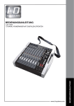
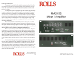
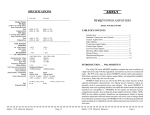
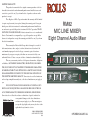
LIMITED WARRANTY
This product is warranted to the original consumer purchaser to be free
from defects in materials and workmanship under normal installation, use and
service for a period of one (1) year from the date of purchase as shown on the
purchaser’s receipt.
The obligation of Rolls Corporation under this warranty shall be limited
to repair or replacement (at our option), during the warranty period of any part
which proves defective in material or workmanship under normal installation,
use and service, provided the product is returned to Rolls Corporation, TRANSPORTATION CHARGES PREPAID. Products returned to us or to an authorized
Service Center must be accompanied by a copy of the purchase receipt. In the
absence of such purchase receipt, the warranty period shall be one (1) year from
the date of manufacture.
This warranty shall be invalid if the product is damaged as a result of
defacement, misuse, abuse, neglect, accident, destruction or alteration of the
serial number, improper electrical voltages or currents, repair, alteration or
maintenance by any person or party other than our own service facility or an
authorized Service Center, or any use violative of instructions furnished by us.
This one-year warranty is in lieu of all expressed warranties, obligations
or liabilities. ANY IMPLIED WARRANTIES, OBLIGATIONS, OR LIABILITIES, INCLUDING BUT NOT LIMITED TO THE IMPLIED WARRANTIES
OF MERCHANTABILITY AND FITNESS FOR A PARTICULAR PURPOSE,
SHALL BE LIMITED IN DURATION TO THE ONE YEAR DURATION OF
THIS WRITTEN LIMITED WARRANTY. Some states do not allow limitations
on how long an implied warranty lasts, so the above limitation may not apply to
you.
IN NO EVENT SHALL WE BE LIABLE FOR ANY SPECIAL, INCIDENTAL OR CONSEQUENTIAL DAMAGES FOR BREACH OF THIS OR
ANY OTHER WARRANTY, EXPRESSED OR IMPLIED, WHATSOEVER.
Some states do not allow the exclusion or limitation of special, incidental or
consequential damages so the above limitation or
exclusion may not apply to you. This warranty gives
you specific legal rights, and you may also have other
rights which vary from state to state.
ROLLS CORPORATION
SALT LAKE CITY, UTAH
6/04
RM82
MIC LINE MIXER
Eight Channel Audio Mixer
1
2
+20
TRIM
6
LEVEL
3
+20
TONE
TRIM
7
LEVEL
4
+20
TONE
8
TRIM
LEVEL
5
+20
TONE
TRIM
LEVEL
+20
TONE
TRIM
LEVEL
TONE
MASTER
MIC/LINE
MIXER
+20
TRIM
LEVEL
+20
TONE
TRIM
LEVEL
+20
TONE
TRIM
LEVEL
0
TONE
10
LEVEL
pwr
RM82
OWNERS MANUAL
INTRODUCTION
SPECIFICATIONS
Thank your for your purchase of the Rolls RM82 Mic Line eight channel audio mixer. It is
intended for sound reinforcement or studio applications where several microphones or
line sources need to be combined to a single output. Please review this manual for proper
operation.
Input Impedance:
Max Input Level:
TABLE OF CONTENTS
1.
INTRODUCTION
TABLE OF CONTENTS
FEATURES
INSPECTION
2.
DESCRIPTION
Front Panel
Rear Panel
3.
CONNECTION
1. Microphone and Main Output Connection
2. Connecting Two RM82 Units Together
3. Channel Direct Output
4. Channel Insertt
4.
OPERATION
Setting the DIP switches
Configuring the unit for Direct Output Operation
Configuring the unit for Insert Operation
Configuring the Output Level
5.
SCHEMATIC
6.
SPECIFICATIONS
BACK COVER
WARRANTY
FEATURES:
• 8 XLR Mic inputs
• 8 1/4” unbalanced line inputs which may be internally jumpered to be Inserts, or Direct
Outputs.
• Individual phantom power switches for each channel
• Front panel Trim and Tone controls
• RCA Aux/Bus input and pre-master output for cascading units or recording
• Balanced XLR output
Input Connectors:
Outputs:
Max Gain:
Tone Control:
Phantom Power:
Output Level:
Output Impedance:
Phase Shift:
Max S/N ratio:
THD:
CMRR:
Size:
Weight:
Mic:
10K Ω XLR balanced
1/4":
20K Ω unbalanced
Bus Input:
10K Ω unbalanced
Mic:
0 dBV balanced
Line:
+6 dBV
8: XLR, 8: 1/4" (Line), 1: RCA (Bus input)
XLR bal., RCA unbalanced Prefade out
Mic:
55 dB
Line:
26 dB
12 dB Treble/Bass cut
+48 VDC
+22 dBV max
51 Ω
<10 degrees, 20Hz to 20 kHz
106 dB
<.01%
>52 dB (Mic)
19" x 1.75" x 6"
(48.3 x 4.5 x 15 cm)
7 lbs. (3 kg)
DIP SWITCH DEFAULT SETTING:
JUMPER DEFAULT SETTING:
ALL OFF
1/4” JACKS AS INPUT
MAIN OUTPUT AS LINE
INSPECTION
1. Unpack and inspect the RM82 box and package.
If obvious physical damage is noticed, contact the carrier immediately to make a damage
claim. We suggest saving the shipping carton and packing materials for safely transporting the unit in the future.
2. Please visit our website at www.rolls.com and register your warranty at the “Register
Your Warranty Here” text, or complete the Warranty Registration Card and return it to the
factory.
1
6
SCHEMATIC
DESCRIPTION
FRONT PANEL
1
2
3
4
5
6
7
8
MASTER
MIC/LINE
MIXER
+20
TRIM
LEVEL
+20
TONE
TRIM
LEVEL
+20
TONE
TRIM
LEVEL
+20
TONE
TRIM
LEVEL
+20
TONE
TRIM
LEVEL
+20
TONE
TRIM
LEVEL
+20
TONE
TRIM
LEVEL
+20
TONE
TRIM
LEVEL
0
TONE
10
LEVEL
pwr
RM82
NOTE: Descriptions for Channels 1 - 8 are identical.
TRIM: Adjusts the sensitivity of the XLR Microphone Inputs.
LEVEL: Adjusts the level of signal in the channel from off to +20 dB of gain.
TONE:Cuts the signal up to 12 dB, below 200 Hz when turned clockwise, or
above 6 kHz when turned counter-clockwise.
MASTER LEVEL: Adjusts the Main Output signal level.
pwr: LED indicating power is applied to the RM82.
Power Switch: Applies power to the unit. Please ensure the power cable is connected to a properly grounded AC outlet.
REAR PANEL
PREFADE
OUT
SERIAL NUMBER
CHANNEL 8
CHANNEL 7
CHANNEL 6
CHANNEL 5
CHANNEL 4
CHANNEL 3
CHANNEL 2
CHANNEL 1
82-
MODEL RM82
PHANTOM POWER
120 VAC
50/60 Hz 15 VA
MADE IN U.S.A.
on
MAIN
OUT
AUX
BUSS IN
8 7 6 5 4 3 2 1
WARNING: DO NOT EXPOSE THIS
OR MOISTURE
EQUIPMENT TO RAIN
CAUTION:
TO REDUCE THE RISK OF ELECTRIC SHOCK DO NOT REMOVE BACK PANEL
NO USER SERVICABLE PARTS INSIDE. REFER SERVICING TO QUALIFIED SERVICE PERSONNEL
RISQUE DE CHOC - NE PAS ENLEVER
MAIN OUTPUT: XLR balanced jack containing the RM82 main output signal.
PRE-FADE OUTPUT: RCA jack for connection to another RM81 Aux/Bus Input or
to another device such as a recorder.
AUX INPUT: RCA jack which connects directly to the RM81 mix bus. The jack
may be connected to another RM81 Pre-Fade Output - making this unit the
“Master”.
PHANTOM POWER SWITCHES: 8 individual DIP switches for applying 48 Volts
of phantom power to the indicated channel’s XLR Input. The phantom power is for
powering condenser microphones. The Phantom Power switches are in the OFF
position when the RM82 is shipped from the factory.
CHANNEL INPUTS 1 - 8: 1/4” TS unbalanced, and XLR balanced input jacks.
The eight 1/4” jacks come from the factory configured as line inputs and are
electrically mixed with the XLR jacks. They may be used together if desired. These
inputs may be reconfigured as either Direct Outputs, or Inserts. See page 4 for
details.
5
A NOTE ABOUT ROLLS MICROPHONE PREAMPLIFIER CIRCUITS
The Rolls servo-balanced Microphone Preamps feature many advantages over
other mic preamps. Among these are simplicity of design, 40db or higher CMRR
(common mode rejection ratio) than transistor input mic preamps. This means
much lower noise on long input lines, and very low distortion at high gain.
Discrete transistor preamps are non-linear at high gains, but not our design. We
feature a higher signal swing, which means our preamps have more headroom
before clipping.
2
CONNECTION
OPERATION
1. MICROPHONE AND MAIN OUTPUT CONNECTION
Connect microphones to the XLR Inputs as shown
here. If the microphones are condenser type, and
require phantom power - remember to switch on
(down) the corresponding
Phantom Power switch.
Connect the Output to the
next device in your signal
chain.
PREFADE
OUT
SERIAL NUMBER
CHANNEL 8
CHANNEL 7
82-
MODEL RM82
120 VAC
50/60 Hz 15 VA
MADE IN U.S.A.
PHANTOM POWER
on
MAIN
OUT
AUX
BUSS IN
8 7 6 5 4 3 2 1
CONFIGURING THE 1/4” INPUT JACKS AS INSERTS
To configure a channel’s 1/4” jack as an Insert, first remove the RM82 lid and
locate the corresponding channel’s dual three-pin header. Move both shorting
jumpers down as shown below as “INSRT”, the jack then becomes an Insert.
WARNING:
2. CONNECTING TWO RM82 UNITS TOGETHER
PREFADE
OUT
SERIAL NUMBER
CHANNEL 8
Using a single RCA
cable, connect from
the Pre-Fader Output
of the “Slave” unit to
the Aux Bus input of
the “Master” unit.
This “Master” unit’s
Master Level control
will now adjust the
overall level of both
units.
CHANNEL 7
82-
MODEL RM82
PHANTOM POWER
on
120 VAC
50/60 Hz 15 VA
MADE IN U.S.A.
MAIN
OUT
AUX
BUSS IN
8 7 6 5 4 3 2 1
PREFADE
OUT
SERIAL NUMBER
MASTER UNIT
WARNING:
CHANNEL 8
CHANNEL 7
82-
MODEL RM82
PHANTOM POWER
on
120 VAC
50/60 Hz 15 VA
MADE IN U.S.A.
MAIN
OUT
AUX
BUSS IN
8 7 6 5 4 3 2 1
SLAVE UNIT
WARNING:
3. CHANNEL DIRECT OUTPUT
For each channel you wish to
have Direct Output access, you
must first configure that
channel’s 1/4” Input as a Direct
Output. Follow the instructions
shown on page 4.
Connect a 1/4” unbalanced TipSleeve cable to the channel’s 1/4” jack and to the next device you want the signal
sent to. Note, the channel’s signal will still be present at the RM82 Main Output.
PREFADE
OUT
SERIAL NUMBER
CHANNEL 8
CHANNEL 7
82-
MODEL RM82
PHANTOM POWER
120 VAC
50/60 Hz 15 VA
MADE IN U.S.A.
CONFIGURING THE 1/4” INPUT JACKS AS DIRECT OUTPUTS
The eight 1/4” Input jacks come from the factory configured as line inputs and are
electrically mixed with the XLR jacks. They may be used together if desired. To
configure a channel’s 1/4” jack as a Direct Out, first remove the RM81 lid. For
each channel there are dual three-pin headers with shorting jumper on two pins.
The setting from the factory is on “IN”. By moving the shorting jumpers to the
configuration shown as “OUT” (one jumper up, the other down), the jack then
becomes a Direct Output.
Direct
Output
Insert
Input
CONFIGURING THE OUTPUT FOR MIC OR LINE LEVEL
The RM82 ships from the factory with the XLR Main Output configured as Line
Level (+4 dB). To change this to Mic Level (-10 dB), carefully remove the lid, locate
the Mic/Line header which is near the Main Output jack. Move the two jumpers
from the Line Level position (shown below on the right), to the Mic Level position
(shown on the left).
on
MAIN
OUT
AUX
BUSS IN
8 7 6 5 4 3 2 1
WARNING:
PREFADE
OUT
SERIAL NUMBER
CHANNEL 8
CHANNEL 7
4. CHANNEL INSERT
For each channel you wish to
have the ability to insert into, you
must first configure that channel’s
1/4” Input as an INSERT. Follow
the instructions shown on page 4.
Connect a 1/4” Tip-Ring-Sleeve
INSERT cable into the channel’s
1/4” jack, and to the processor or other device you want the signal connected to.
82-
Mic
Level
Line
Level
MODEL RM82
PHANTOM POWER
120 VAC
50/60 Hz 15 VA
MADE IN U.S.A.
3
on
MAIN
OUT
AUX
BUSS IN
8 7 6 5 4 3 2 1
WARNING:
JUMPER DEFAULTS
The internal jumpers are configured from the factory as follows:
1/4” = INPUTS
MAIN OUT LEVEL = LINE LEVEL
4